
Effect of Ni interlayer on microstructure of aluminum/magnesium dissimilar metal friction stir welding joint
-
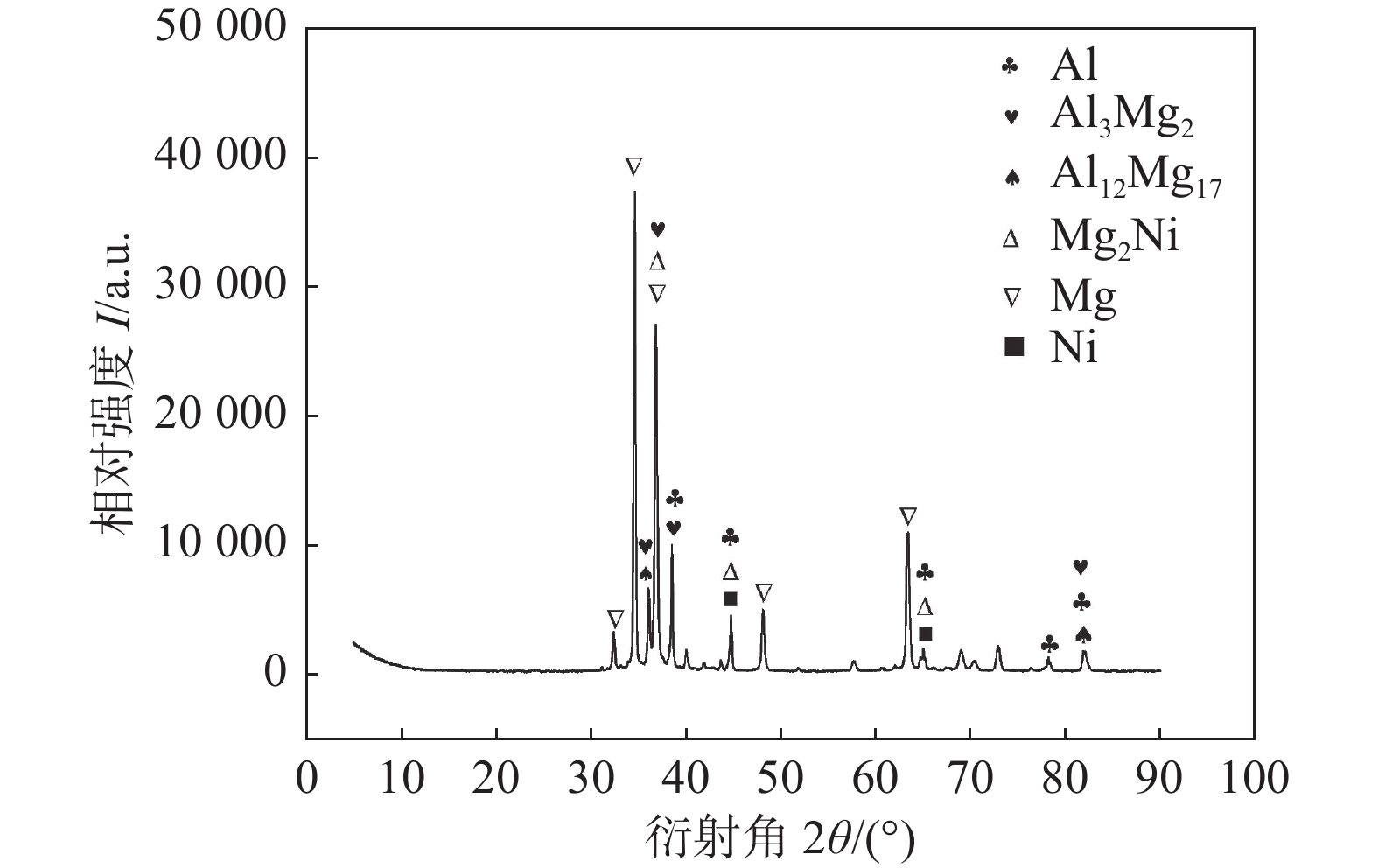
摘要: 采用搅拌摩擦焊(friction stir welding, FSW),引入厚度为0.05 mm镍箔作为中间层,在焊接速度不变条件下,采用不同转速对厚度为4 mm的6061铝合金和AZ31镁合金进行平板对接,对接头进行系列微观组织表征及力学性能测试,探讨转速对接头中镍颗粒分布状态,金属间化合物(intermetallic compounds, IMCs)种类与分布及接头强度的影响规律. 研究结果表明:与未引入中间层接头相比,引入镍改变了铝/镁异种金属FSW接头焊核区(weld nugget zone, WNZ)中IMCs种类及分布,WNZ存在明显的镁合金与铝合金相间的带状组织,其上分布着絮状Al12Mg17、颗粒状Mg2Ni、层状Al3Mg2及大小不一的镍箔颗粒;随着转速增加,镍箔颗粒分布愈加均匀,Al3Mg2数量相对减少,且脆性Al3Mg2由连续分布逐渐演变为断续分布;当转速为750 r/min时,接头抗拉强度达到最大值,与未引入中间层接头相比,引入镍中间层接头抗拉强度提高了56 MPa,达到镁合金的56.9%.Abstract: The flat butt welding tests were carried out on 6061 aluminum alloy and AZ31 magnesium alloy with the thickness of 4 mm by introducing 0.05 mm Ni foil interlayer under the condition of constant travel speed and different rotation speeds using the friction stir welding (FSW) technology. The effects of rotation speeds on the distribution of Ni foil particles, the types and distribution of the intermetallic compounds (IMCs) and the strength of the joints were investigated by series of microstructure characterization and mechanical property tests. The results showed that compared to the joint without Ni, the introduction of Ni foil interlayer changed the types and distribution of IMCs in the weld nugget zone (WNZ). In WNZ, there was an obvious banded structure between magnesium alloy and aluminum alloy on which the flocculent Al12Mg17, granular Mg2Ni, lamellar Al3Mg2, and Ni foil particles of varying sizes were distributed. With the increasing of rotation speed, the distribution of Ni became more uniform, while the Al3Mg2 decreased relatively, and the distribution of the brittle Al3Mg2 gradually changed from continuous to intermittent. The tensile strength of the joint reached the maximum value when the rotation speed was 750 r/min. Compared to the joint without Ni, the tensile strength of the joint with the introduction of Ni foil interlayer was increased by 56 MPa, which was 56.9% of the strength of magnesium alloy.
-
0. 序言
随着各国对能源尤其是对传统的石油和天然气资源的需求量的不断提高,深水油气获得了极大的开采空间,海洋资源的综合利用效率也将不断提高,将为油气资源开发以及海洋经济的发展发挥更加重要的作用[1]. 海洋立管系统是深海资源开发的关键部分,其中SCR具有较小的管径和较大的壁厚,具有成本低、适用于高温高压环境的优点,在国内外具有广阔的应用前景[2-3]. 然而,SCR在长期服役过程中会持续受到油气资源中H2S的侵蚀,造成不同程度的氢脆. 不同服役时间的立管受到H2S的作用时间不同,在管道内壁存在的H2S和与外壁接触的海洋环境腐蚀以及应力作用下,容易在管道尤其是焊接接头处发生SCC.
目前国内外有关海洋环境SCC的研究较多. Han等人[4]研究了预应变对X65管线钢大变形CGHAZ对硫化物SCC敏感性的影响. 结果表明,预应变后试样的微观组织变化不大,但预应变使得抗硫化物SCC性能和断裂韧性具有协同提高作用. Yang等人[5]研究了充氢对模拟深海水环境中X70钢电化学和SCC行为的影响. 结果表明,随着充氢电流密度的增加,X70钢的SCC敏感性先降低后升高. Wang等人[6]研究了Incoloy825/X65双金属复合管焊接接头在湿H2S环境中的SCC行为. 结果表明,在湿H2S环境中,复合管焊接接头中出现了两类裂纹,产生机理均为阳极溶解、应力和氢的共同作用.
有关SCR的研究主要集中在SCR的安装、焊接工艺和疲劳机制等方面,SCC方面的研究未见系统深入的报道[7-9]. 因此,为完善SCR焊接接头处应力腐蚀敏感性和开裂机理,提高海洋油气资源的深海勘探效率和安全性,对SCR应力腐蚀相关机理的研究十分必要. 文中选取酸性服役环境下常用的X65管线钢,采取冷金属过渡弧焊(cold metal transfer,CMT)打底,熔化极气体保护焊(gas metal arc welding,GMAW)填充的SCR焊接工艺,探究不同预充氢时间对X65制SCR焊接接头在NaCl腐蚀液以及H2S环境中应力腐蚀敏感性变化的影响.
1. 试验方法
试验所用焊丝为ER70S-6,直径为1.00 mm,试验的母材为酸性服役环境下常用的X65管线钢,主要化学成分如表1和表2所示. 根据SCR焊接需要,焊缝为环焊缝,焊接位置选择管道水平固定焊. 采用CMT进行打底焊,保护气体为50% CO2 + 50% Ar,采用GMAW进行热焊和填充焊,其中填充焊采用7层,采用保护气体为20% CO2 + 80% Ar. 具体焊接参数如表3所示. 焊前设置单U形坡口,形状尺寸如图1所示.
表 1 ER70S-6焊丝化学成分(质量分数,%)Table 1. ER70S-6 welding wire chemical compositionsC Mn Si P S Fe 0.10 1.70 1.10 0.015 0.008 余量 表 2 X65钢的主要化学成分(质量分数,%)Table 2. Main chemical compositions of X65 steelC Si Mn Nb Ti S Ni P Cu Fe 0.098 0.196 1.193 0.022 0.003 0.003 0.027 0.013 0.067 余量 表 3 焊接工艺参数Table 3. Welding process parameters焊接方法 焊接电流
I/A电弧电压
U/V焊接速度
v/(mm·min−1)保护气流量
Q/(L·min−1)焊丝伸出长度
L/mmCMT 142 ~ 144 13.2 ~ 13.7 360 ~ 470 30 8 ~ 10 GMAW 188 ~ 206 21.6 ~ 22.0 360 ~ 470 30 8 ~ 10 试验所用工件取自于采用上述工艺所得的环焊缝,取样示意图及试样的形状与尺寸如图2所示. 对切割好的试样进行金相观察,并通过微观组织来分析各区域的性能. 为了模拟SCR在服役过程中管内的腐蚀环境,在参考美国标准NACE TM0284-2016《管道、压力容器抗氢致开裂钢性能评价的试验方法》基础上,采用Na2S2O3代替H2S气体以提高试验安全性,其可靠性已得到文献[4, 10]证明,因此H2S选择使用5%NaCl + 0.5%CH3COOH + 0.001 mol/L Na2S2O3的混合溶液,腐蚀液浓度相当于0.000 704%. 此外,3.5%NaCl溶液能较好地模拟真实海水盐浓度[11-12]. 选择3.5%NaCl溶液作为模拟海洋环境的腐蚀液.
![]() 图 2 取样示意图及试样形状尺寸Figure 2. Sampling diagram and sample shape and size. (a) sampling diagram; (b) SSRT sample (mm)
图 2 取样示意图及试样形状尺寸Figure 2. Sampling diagram and sample shape and size. (a) sampling diagram; (b) SSRT sample (mm)采用浸泡法对试样进行预充氢处理,选择的充氢溶液为5% NaCl + 0.5% CH3COOH + 0.001 mol/L Na2S2O3的混合溶液,分别对试样预充氢1,2,3天和4天. 文献[13]研究表明,在NACE溶液中浸泡时,抗硫类钢将和溶液产生的H2S反应产生FeS膜以及吸附试样周围的氢原子. 其中部分氢原子渗入试样并固溶在试样中,从而达到预充氢的目的. 对未充氢以及预充氢时间为1,2,3天和4天的试样,分别在空气和两种腐蚀环境中进行SSRT,根据试验数据来探究预充氢对试样应力腐蚀敏感性的影响. 通过ZEISS Sigma 300扫描电子显微镜对试样的断口进行观察,对试样断裂的影响因素以及断裂机理等进行分析.
2. 试验结果与分析
2.1 微观组织分析
在500倍光学显微镜下,对X65钢焊接试样的母材、热影响区和焊缝区域进行金相观察,显微组织如图3所示. 由图3可知,X65钢母材中准多边形铁素体(quasi-polygonal ferrite,QF)含量较高,并含有板条贝氏体(lath bainite,LB)和弥散的粒状碳化物.焊缝区域主要由PF、针状铁素体(acicular ferrite,AF)、粒状贝氏体(granular bainite,GB)和呈羽毛状的上贝氏体(upper bainite,UB)组成. FGHAZ主要由细小且均匀的F和P组成,使该区域力学性能显著优于其他热影响区域. CGHAZ内部含有GB、M-A组元、AF和PF. 此区域的焊接热循环特征为升温速度快、峰值温度高,奥氏体晶粒在形成时急剧长大,在冷却后得到粗大的组织,使力学性能显著下降. M-A组元较粗大,容易在腐蚀环境中溶解,使得材料自发生成的保护膜产生孔洞,从而降低材料的抗SCC性能[14].
![]() 图 3 试样金相组织Figure 3. Metallographic structure of the samples. (a) base metal; (b) weld metal; (c) fine grain zone; (d) coarse grain zone
图 3 试样金相组织Figure 3. Metallographic structure of the samples. (a) base metal; (b) weld metal; (c) fine grain zone; (d) coarse grain zone2.2 SSRT结果分析
采用Cortest应力腐蚀疲劳设备进行SSRT,对H2S以及3.5% NaCl溶液中的SCC性能进行研究. 将未充氢以及预充氢时间为1,2,3天和4天的试样分别在空气、3.5% NaCl溶液和H2S腐蚀环境中以1 × 10⁻⁶ s−1的应变速率进行拉伸. 所有试样的力学性能数据如表4所示. 在空气环境下,不同的预充氢时间对塑性的影响较小,但从最大应力能看出,预充氢试样较未充氢试样的抗拉强度显著下降.
表 4 不同环境下SSRT数据Table 4. SSRT datas in different environments环境
类型预充氢时间t/天 断后伸长率 Α(%) 断面收缩率 Z(%) 最大应力 σmax/MPa 最大应变 εmax(%) 空气 0 3.69 76 656 15 1 3.77 81 575 16 2 3.70 81 568 16 3 3.53 82 576 17 4 4.10 82 538 15 NaCl溶液 0 3.68 76 626 18 1 3.55 79 577 17 2 3.39 78 582 17 3 2.94 74 579 18 4 3.37 73 527 13 H2S 0 2.07 67 577 11 1 1.60 69 577 11 2 2.00 72 565 12 3 2.16 52 560 10 4 2.15 44 504 8 在NaCl溶液及H2S腐蚀环境中进行拉伸的试样,预充氢时间对断后伸长率的影响较小,但从最大应变和断面收缩率可以看出,预充氢4天的试样力学性能明显下降,尤其是在H2S腐蚀环境中,断面收缩率由未充氢的67%下降至44%. 此外,结合SSRT试验数据,进行计算处理得到应力−应变曲线如图4所示. 由图4可知,在同一环境下,不同预充氢天数的应力−应变曲线在前期弹性阶段几乎重合,但同一环境下未充氢试样的屈服强度和抗拉强度比其他预充氢试样整体偏大. 此外,预充氢前3天的应力−应变曲线变化不大,但预充氢4天的试样在3种环境下的应力−应变曲线都有较大变化,其屈服强度、抗拉强度和最大应变等性能均发生了显著下降. 应力腐蚀敏感性与空气和两种腐蚀环境下断面收缩率、断后伸长率和最大应力等参数的变化程度有关. 为了对试样的应力腐蚀敏感性进行定量分析,试验采用断面收缩率作为指标来计算应力腐蚀敏感性系数,以此来定量代表试样的应力腐蚀敏感性. 试样的应力腐蚀敏感性系数为
![]() 图 4 3种环境下不同预充氢时间的应力−应变曲线对比Figure 4. Comparison of stress-strain curves with different hydrogen pre-charging time in three environment. (a) air; (b) corrosion environment of NaCl solution; (c) corrosion environment of H2S
图 4 3种环境下不同预充氢时间的应力−应变曲线对比Figure 4. Comparison of stress-strain curves with different hydrogen pre-charging time in three environment. (a) air; (b) corrosion environment of NaCl solution; (c) corrosion environment of H2S$$ E_{Z} = \left(1-\frac{Z_{\text {1}}}{Z_{\text {0}}}\right) \times 100 \% $$ (1) 式中:Z1为腐蚀环境中试样的断面收缩率;Z0为空气环境中试样的断面收缩率.
应力腐蚀敏感性系数EZ越大,代表以断面收缩率为指标时,试样在该腐蚀溶液中的抗SCC能力越差、应力腐蚀敏感性越高. 应力腐蚀敏感性系数EZ计算结果,如图5所示. 试样在H2S腐蚀环境中的应力腐蚀敏感性要显著高于NaCl溶液. 在H2S腐蚀环境中,应力腐蚀敏感性最低为预充氢2天试样(EZ为11.09%),最高为预充氢4天试样(EZ为46.38%);而在NaCl溶液中,应力腐蚀敏感性最高为预充氢4天试样(EZ为11.14%),与NACE A溶液环境下EZ最低值接近,并且为最高值的1/4. 对预充氢时间进行分析可知,在NaCl溶液腐蚀环境下,预充氢能够增加试样的应力腐蚀敏感性,随着预充氢时间的增长,同一环境下试样的应力腐蚀敏感性逐渐增大,并且从第3天开始应力腐蚀敏感性有大幅度的增加,当第4天时达到最大. 在H2S腐蚀环境中,预充氢对试样应力腐蚀敏感性的影响规律与NaCl溶液腐蚀环境接近,但从预充氢2天增加至4天的过程中,试样应力腐蚀敏感性的增长幅度大于NaCl溶液腐蚀环境,这是由于预充氢与H2S对材料应力腐蚀具有协同作用,从而导致应力腐蚀敏感性更容易增大.
![]() 图 5 不同预充氢时间在两种腐蚀环境下的EZ值Figure 5. EZ values for different hydrogen pre-charging time in two corrosive environment
图 5 不同预充氢时间在两种腐蚀环境下的EZ值Figure 5. EZ values for different hydrogen pre-charging time in two corrosive environment2.3 断口分析
为进一步对试样应力腐蚀敏感性进行分析,采用ZEISS Sigma 300扫描电镜对试样进行断口分析,试样宏观断口形貌如图6所示. 根据2.2节可知,预充氢4天的试样应力腐蚀敏感性最高,与其他预充氢时间相比具有显著差异,故仅选择3种环境下未充氢以及预充氢4天的试样进行断口分析. 由图6(a)和图6(d)可知,空气环境下未充氢和预充氢4天的试样断口均呈现出明显的颈缩现象,并且断口表面粗糙,产生较多凹坑,可观察到显著的塑性流动现象. 断口可见较多的韧窝,为典型的韧性断裂特征. 此外,未充氢试样比预充氢4天的颈缩程度更大,说明预充氢使得试样的韧性下降,这和前文对SSRT试验结果的分析一致. 观察图6(b)和图6(e)可知,NaCl溶液中的未充氢试样断口同样呈现出明显的颈缩现象,而预充氢4天试样的断口虽然可以观察到部分韧窝,但是颈缩现象不明显,并且表面较为平整,这同样说明预充氢时间达到一定值时,试样的韧性会有显著下降. 观察图6(c)和图6(f)可知,H2S腐蚀环境中的未充氢试样断口仍可以观察到大小不一的韧窝,但颈缩现象不明显,说明与其他两种环境相比,试样在H2S腐蚀环境下塑性下降最多. 而预充氢4天时断口观察不到明显的颈缩现象,且表面相对平整,并且基本不存在较大的韧窝形状,只能观察到少数细微的孔洞. 此外,在两个断口表面还存在部分舌状花样和河流状花纹,故试样此时的断裂方式为准解理断裂.
![]() 图 6 3种环境下未充氢及预充氢4天试样正面断口宏观形貌Figure 6. Macroscopic fracture morphology of the hydrogen uncharged and four days hydrogen pre-charging samples in three environment. (a) hydrogen uncharged samples in air; (b) hydrogen uncharged samples in the corrosion environment of NaCl solution; (c) hydrogen uncharged samples in the corrosion environment of H2S; (d) four days hydrogen pre-charging samples in air; (e) four days hydrogen pre-charging samples in the corrosion environment of NaCl solution; (f) four days hydrogen pre-charging samples in the corrosion environment of H2S
图 6 3种环境下未充氢及预充氢4天试样正面断口宏观形貌Figure 6. Macroscopic fracture morphology of the hydrogen uncharged and four days hydrogen pre-charging samples in three environment. (a) hydrogen uncharged samples in air; (b) hydrogen uncharged samples in the corrosion environment of NaCl solution; (c) hydrogen uncharged samples in the corrosion environment of H2S; (d) four days hydrogen pre-charging samples in air; (e) four days hydrogen pre-charging samples in the corrosion environment of NaCl solution; (f) four days hydrogen pre-charging samples in the corrosion environment of H2S试样断口的韧窝数量越少、直径越小,代表材料韧性越差,断面收缩率越小,故通过比较试样在空气和腐蚀环境下韧窝之差,可以判断两种环境下断面收缩率的差距大小,根据式(1)可进一步判断试样应力腐蚀敏感性的大小. 故采用扫描电镜对断口形貌放大2000倍,通过对比断口微观形貌以及韧窝情况来进行判断,如图7所示. 观察图7(a)和图7(b)可知空气和NaCl溶液腐蚀环境下,对于未充氢试样,两种环境下试样断口的韧窝都较多,属于明显的韧性断裂,并且韧窝差距不大,结合图5可知,未充氢条件下NaCl溶液中试样EZ为0.67%,故判断未充氢试样的应力腐蚀敏感性较小. 观察图7(d)和图7(e)可知,对于预充氢4天试样断口,NaCl溶液腐蚀环境产生了明显的岩石状形貌,有较多半圆状条纹,属于准解理断裂特征,其韧窝数量和大小都明显不如空气环境,结合图5可知,此条件下EZ为11.14%,说明此时试样应力腐蚀敏感性较未充氢情况显著增大. 对比空气和H2S腐蚀环境试样断口可得到类似的结论. H2S腐蚀环境预充氢4天试样表面存在腐蚀产物,从未经腐蚀的区域可以观察韧窝现象. 观察图7(f)可知,相比未充氢试样,预充氢4天试样在H2S腐蚀环境中的韧窝现象相对空气环境明显减少,结合图5可知,H2S腐蚀环境下,EZ值在未充氢和预充氢4天条件下分别为11.96%和46.38%,同样说明预充氢导致试样应力腐蚀敏感性增大.
![]() 图 7 3种环境下未充氢及预充氢4天试样正面断口微观形貌Figure 7. Micromorphology fracture morphology of the hydrogen uncharged and four days hydrogen pre-charging samples in three environment. (a) hydrogen uncharged samples in air; (b) hydrogen uncharged samples in the corrosion environment of NaCl solution; (c) hydrogen uncharged samples in the corrosion environment of H2S; (d) four days hydrogen pre-charging samples in air; (e) four days hydrogen pre-charging samples in the corrosion environment of NaCl solution; (f) four days hydrogen pre-charging samples in the corrosion environment of H2S
图 7 3种环境下未充氢及预充氢4天试样正面断口微观形貌Figure 7. Micromorphology fracture morphology of the hydrogen uncharged and four days hydrogen pre-charging samples in three environment. (a) hydrogen uncharged samples in air; (b) hydrogen uncharged samples in the corrosion environment of NaCl solution; (c) hydrogen uncharged samples in the corrosion environment of H2S; (d) four days hydrogen pre-charging samples in air; (e) four days hydrogen pre-charging samples in the corrosion environment of NaCl solution; (f) four days hydrogen pre-charging samples in the corrosion environment of H2S对未充氢以及预充氢4天,在3种环境下拉伸的试样断口附近侧面形貌进行分析,如图8所示. 由图可知,6组试样断口组织变化不大,主要包括QF,GB,AF和M-A组元等. 此外,除空气和NaCl溶液腐蚀环境下未充氢试样表面外,其余4组试样表面存在较多孔洞和微裂纹. 通过对比图8(a)和图8(d)、对比图8(b)和图8(e)可知,试验进行的预充氢使材料内部微裂纹和孔洞现象加剧,结合图4中空气环境未充氢试样与其余环境试样的应力−应变曲线差异可知,预充氢使得材料塑性、韧性和强度明显下降,进而在腐蚀环境和应力作用下更易发生开裂,材料抗SCC能力降低. 微裂纹和孔洞主要起源于原奥氏体晶界和M-A组元. 原奥氏体晶界附近容易产生杂质和合金元素的偏析,造成晶界之间结合强度下降,造成应力集中,导致细微裂纹的产生. 此外,由于预充氢和H2S腐蚀环境都使得试样内部存在较多氢原子,并容易聚集在这些缺陷处,从而产生新的氢分子,故部分原奥氏体晶界处产生了较大氢压,由此导致氢致裂纹和孔洞的产生. 裂纹持续长大会使材料脆化加剧,进而导致SCC. 而产生于M-A组元的微裂纹与孔洞主要位于M-A组元和F基体的界面处.
![]() 图 8 3种环境下未充氢及预充氢4天试样断口附近侧面微观形貌Figure 8. Microscopic morphology of the side near the hydrogen uncharged and four days hydrogen precharging samples fracture in three environment. (a) hydrogen uncharged samples in air; (b) hydrogen uncharged samples in the corrosion environment of NaCl solution; (c) hydrogen uncharged samples in the corrosion environment of H2S; (d) four days hydrogen pre-charging samples in air; (e) four days hydrogen pre-charging samples in the corrosion environment of NaCl solution; (f) four days hydrogen pre-charging samples in the corrosion environment of H2S
图 8 3种环境下未充氢及预充氢4天试样断口附近侧面微观形貌Figure 8. Microscopic morphology of the side near the hydrogen uncharged and four days hydrogen precharging samples fracture in three environment. (a) hydrogen uncharged samples in air; (b) hydrogen uncharged samples in the corrosion environment of NaCl solution; (c) hydrogen uncharged samples in the corrosion environment of H2S; (d) four days hydrogen pre-charging samples in air; (e) four days hydrogen pre-charging samples in the corrosion environment of NaCl solution; (f) four days hydrogen pre-charging samples in the corrosion environment of H2S结合文献[15-16]可知,较软F和沉淀于F之上的硬M-A组元在一起形成了腐蚀性微电池,并产生微耦合效应. 其中作为阴极的M-A组元,加速了F的阳极溶解,促进点蚀坑的形成. 在外界拉应力作用下,M-A组元周围容易产生位错的不断堆积和应力集中,进而促进裂纹萌生和扩展. M-A组元具有很强的氢捕获特性,使得其内部也容易产生氢致裂纹和孔洞.
观察图8中组织可知,微裂纹主要被QF晶界以及AF所终止,GB在其中几乎没有发挥作用. 结合文献[17-19]可知,首先,微裂纹生长方向呈特定角度时,容易被大角度的QF晶界阻止,在此处继续进行扩展需要更多能量,从而使得裂纹的扩展受到阻碍. 而GB虽然数量多,但晶界取向接近,一般为低于15°的小角度晶界,比QF晶界对裂纹的阻碍作用小. 试样中的AF可以使组织均匀化、晶粒细化,并且对裂纹尖端扩展呈阻碍作用,使裂纹扩展方向发生变化,或者通过释放裂纹尖端应力集中,使得裂纹停止继续扩展.
3. 结论
(1) X65焊接接头CGHAZ存在大块PF和M-A组元等组织,此处容易产生裂纹的萌生和扩展.
(2)预充氢能够降低试样在空气和两种腐蚀环境下的力学性能并使应力腐蚀敏感性升高,对于未充氢试样,NaCl溶液腐蚀环境的应力腐蚀敏感性系数EZ和H2S腐蚀环境的EZ分别为0.67%和11.96%,而当预充氢4天时,NaCl溶液腐蚀环境的EZ和H2S腐蚀环境的EZ分别达到11.14%和46.38%.
(3)试样在空气环境主要发生韧性断裂,在NaCl溶液和H2S两种腐蚀环境中主要发生了准解理断裂. 且预充氢4天的试样在腐蚀环境下的韧窝情况较空气环境显著下降,应力腐蚀敏感性增加. 此外,微裂纹和孔洞主要产生于M-A组元以及原奥氏体晶界附近,并且预充氢提供给试样的固溶氢原子容易聚集在这两种区域,从而产生氢致裂纹.
(4)试样在H2S腐蚀环境下的应力腐蚀敏感性系数EZ显著大于NaCl溶液腐蚀环境. 随着预充氢时间的增加,H2S腐蚀环境下试样EZ的增长幅度也大于NaCl溶液腐蚀环境增长幅度.
-
![]()
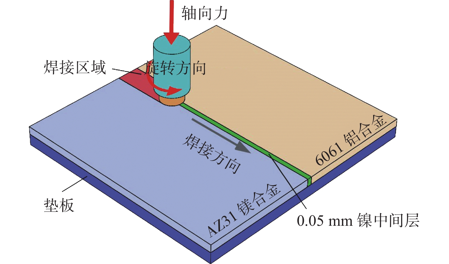
图 1 引入镍中间层铝/镁异种金属FSW装配示意图
Figure 1. Schematic diagram of Al/Mg dissimilar metal FSW process with introduction of Ni interlayer
![]()
图 2 引入镍中间层FSW接头WNZ微观组织及镍元素分布
Figure 2. Microstructure and Ni distribution of FSW joint WNZ with Ni interlayer. (a) rotation speed 450 r/min;(b) rotation speed 550 r/min; (c) rotation speed 650 r/min; (d) rotation speed 750 r/min; (e) rotation speed 850 r/min
![]()
![]()
图 5 不同转速下引入镍中间层铝/镁异种金属FSW接头WNZ微观组织
Figure 5. Microstructure of WNZ of Al/Mg dissimilar metal FSW joint with Ni interlayer under different rotation speeds. (a) rotation speed 450 r/min; (b) rotation speed 550 r/min; (c) rotation speed 650 r/min; (d) rotation speed 750 r/min
![]()
图 6 不同转速下FSW接头工程应力—应变曲线及抗拉强度
Figure 6. Engineering stress —strain curve and tensile strength of the FSW joints under different rotation speeds. (a) engineering stress—strain curve; (b) tensile strength
![]()
图 7 未引入镍中间层FSW接头WNZ微观组织
Figure 7. Microstructure of WNZ of FSW joint without Ni interlayer. (a) bottom of WNZ near Mg side; (b) upper of WNZ near Mg side
表 1 6061铝合金和AZ31镁合金的化学成分(质量分数,%)
Table 1 Chemical compositions of 6061 aluminum alloys and AZ31 magnesium alloys
材料 Si Fe Cu Mn Cr Zn Ti Ni Al Mg 6061 0.55 0.4 0.25 0.074 0.08 0.12 0.08 — 余量 0.8 AZ31 0.28 0.001 0.002 0.33 — 0.71 — 0.0005 2.8 余量  下载: 导出CSV
表 2 焊接工艺参数
Table 2 Welding process parameters
转速
n/(r·min−1)焊接速度
v/(mm·min−1)偏铝侧偏移量
d/mm下压量
h/mm倾角
α(°)450,550,650,
750,85020 0.3 0.2 2.5
下载: 导出CSV
表 3 WNZ内典型IMCs EDS分析结果(原子分数,%)
Table 3 EDS results of typical IMCs in WNZ
位置 Al Mg Ni 相 1 57.52 42.28 0.20 Al3Mg2 2 56.29 42.60 1.11 Al3Mg2 3 3.02 96.52 0.46 Mg基体 4 35.27 64.62 0.11 Al12Mg17 + Mg 5 2.16 92.47 5.37 Mg2Ni + Mg
下载: 导出CSV
-
[1] Zhao Y, Lu Z P, Yan K, et al. Microstructural characterizations and mechanical properties in underwater friction stir welding of aluminum and magnesium dissimilar alloys[J]. Materials & Design, 2015, 65: 675 − 681.
[2] 陈影, 沈长斌, 葛继平. Mg/Al异种金属焊接的研究现状[J]. ·稀有金属材料与工程, 2012, 41(supplement 2): 109 − 11. Chen Ying, Shen Changbin, Ge Jiping. Research progress on the welding of Mg/Al dissimilar metals[J]. Rare Metal Materials and Engineering, 2012, 41(supplement 2): 109 − 11.
[3] Dorbane A, Mansoor B, Ayoub G, et al. Mechanical, microstructural and fracture properties of dissimilar welds produced by friction stir welding of AZ31B and Al6061[J]. Materials Science & Engineering A, 2015, 650: 720 − 733.
[4] Rao H M, Ghaffari B, Yuan W, et al. Effect of process parameters on microstructure and mechanical behaviors of friction stir linear welded aluminum to magnesium[J]. Materials Science & Engineering A, 2016, 651: 27 − 36.
[5] Fu B L, Qin G L, Li F. Friction stir welding process of dissimilar metals of 6061-T6 aluminum alloy to AZ31B magnesium alloy[J]. Journal of Materials Processing Technology, 2015, 218: 38 − 47. doi: 10.1016/j.jmatprotec.2014.11.039
[6] Mo S X, Dong S K, Zhu H, et al. Corrosion behavior of aluminum/steel dissimilar metals friction stir welding joint[J]. China Welding, 2021, 30(3): 20 − 30.
[7] 许志武, 李政玮, 冯艳, 等. 静轴肩辅助铝镁搅拌摩搭接接头的组织与性能[J]. 焊接学报, 2017, 38(4): 1 − 6. Xu Zhiwu, Li Zhengwei, Feng Yan, et al. Microstructure and mechanical properties of Mg/Al friction stir lap welding joint assisted by stationary shoulder[J]. Transactions of the China Welding Institution, 2017, 38(4): 1 − 6.
[8] 李达, 孙明辉, 崔占全. 工艺参数对铝镁搅拌摩擦焊焊缝成形质量的影响[J]. 焊接学报, 2011, 32(8): 97 − 100. Li Da, Sun Minghui, Cui Zhanquan. Effect of parameters on friction stir welding joint of Al and Mg[J]. Transactions of the China Welding Institution, 2011, 32(8): 97 − 100.
[9] Verma J, Taiwade R V, Reddy C, et al. Effect of friction stir welding process parameters on Mg-AZ31B/Al-AA6061 joints[J]. Materials and Manufacturing Processes, 2018, 33(3): 308 − 314. doi: 10.1080/10426914.2017.1291957
[10] Sachin K, Wu C S. Suppression of intermetallic reaction layer by ultrasonic assistance during friction stir welding of Al and Mg based alloys[J]. Journal of Alloys and Compounds, 2020, 827: 154343. doi: 10.1016/j.jallcom.2020.154343
[11] Boccarusso L, Astarita A, Carlone P, et al. Dissimilar friction stir lap welding of AA 6082-Mg AZ31: Force analysis and microstructure evolution[J]. Journal of Manufacturing Processes, 2019, 44: 376 − 388. doi: 10.1016/j.jmapro.2019.06.022
[12] Sun T, Wu S Y, Shen Y F, et al. Effect of traverse speed on the defect characteristic, microstructure, and mechanical property of friction stir welded T-joints of dissimilar Mg/Al alloy[J]. Advances in Materials Science and Engineering, 2020, 2020(3): 1 − 15.
[13] Bandi A, Bakshi S R. Effect of pin length and rotation speed on the microstructure and mechanical properties of friction stir welded lap joints of AZ31B-H24 Mg alloy and AA6061-T6 Al alloy[J]. Metallurgical and Materials Transactions A, 2020, 51(12): 6269 − 6282. doi: 10.1007/s11661-020-06020-8
[14] Niu S Y, Ji S D, Yan D J, et al. AZ31B/7075-T6 alloys friction stir lap welding with a zinc interlayer[J]. Journal of Materials Processing Technology, 2019, 263: 82 − 90. doi: 10.1016/j.jmatprotec.2018.08.009
[15] Gan R G, Jin Y H. Friction stir-induced brazing of Al/Mg lap joints with and without Zn interlayer[J]. Science and Technology of Welding and Joining, 2018, 23(2): 164 − 171. doi: 10.1080/13621718.2017.1354545
[16] Zheng B, Zhao L, Lv Q Q, et al. Effect of Sn interlayer on mechanical properties and microstructure in Al/Mg friction stir lap welding with different rotational speeds[J]. Materials Research Express, 2020, 7(7): 076504. doi: 10.1088/2053-1591/ab9fbb
[17] Liu J L, Niu S Y, Ren R, et al. Improving joint morphologies and tensile strength of Al/Mg dissimilar alloys friction stir lap welding by changing zn interlayer thickness[J]. Acta Metallurgica Sinica (English Letters), 2019, 32(11): 1385 − 1395. doi: 10.1007/s40195-019-00937-9
[18] Zhang J, Luo G Q, Wang Y Y, et al. An investigation on diffusion bonding of aluminum and magnesium using a Ni interlayer[J]. Materials Letters, 2012, 83: 189 − 191. doi: 10.1016/j.matlet.2012.06.014
[19] Shi H, Chen K, Liang Z Y, et al. Intermetallic compounds in the banded structure and their effect on mechanical properties of Al/Mg dissimilar friction stir welding joints[J]. Journal of Materials Science and Technology, 2017, 33(4): 359 − 366. doi: 10.1016/j.jmst.2016.05.006
[20] 朱浩, 张二龙, 莫淑娴, 等. 带状组织对铝/镁异种金属搅拌摩擦焊接头力学性能的影响[J]. 焊接学报, 2020, 41(1): 34 − 38,66. Zhu Hao, Zhang Erlong, Mo Shuxian, et al. Effect of banded structure on mechanical properties of aluminum/magnesium dissimilar metal friction stir welding joint[J]. Transactions of the China Welding Institution, 2020, 41(1): 34 − 38,66.
[21] Dupin N, Ansara I, Sundman B. Thermodynamic re-assessment of the ternary system Al-Cr-Ni[J]. Calphad, 2001, 25(2): 279 − 298. doi: 10.1016/S0364-5916(01)00049-9
[22] Peng P, Wang W, Zhang T, et al. Effects of interlayer metal on microstructures and mechanical properties of friction stir lap welded dissimilar joints of magnesium and aluminum alloys[J]. Journal of Materials Processing Technology, 2021, 299: 117362.
[23] Hajjari E, Divandari M, Razavi S H, et al. Dissimilar joining of Al/Mg light metals by compound casting process[J]. Journal of Materials Science, 2011, 46(20): 6491 − 6499. doi: 10.1007/s10853-011-5595-4
[24] Chang W S, Rajesh S R, Chun C K, et al. Microstructure and mechanical properties of hybrid laser-friction stir welding between AA6061-T6 Al alloy and AZ31 Mg alloy[J]. Journal of Materials Science and Technology, 2011, 27(3): 199 − 204. doi: 10.1016/S1005-0302(11)60049-2


计量
- 文章访问数: 334
- HTML全文浏览量: 38
- PDF下载量: 83
