
Microstructure and corrosion properties of 625 Ni-based alloy surfacing layer on the inner-wall of oil pipe prepared by twin tungsten electrode TIG welding with heat wire
-
摘要:
采用由独立电源控制的双钨极热丝TIG技术在输油管道高强钢内壁制备两层Inconel 625镍基合金堆焊层,并取样对镍/钢堆焊复合板进行800 ℃和900 ℃固溶处理. 用金相显微镜和扫描电镜对焊态下和固溶处理下镍/钢堆焊复合板的微观组织形貌和构成进行分析,对镍/钢复合板进行硬度和电化学腐蚀测试,并对镍基合金堆焊层表面的钝化膜进行XPS分析. 结果表明,焊态下,第一层镍基合金堆焊层垂直于高强钢向上有序生长,第二层镍基合金堆焊层分别以第一层基体和基体内析出物为形核质点,垂直向上生长的顺序变得杂乱; 由于第二层对第一层的再加热作用,第一层镍基合金层比第二层晶粒尺寸更细小;固溶处理后,镍/钢堆焊复合板中钢热影响区组织比焊态下更加均匀细化. 镍/钢堆焊复合板焊态组织中显微硬度呈现梯度分布特征,具体表现为镍基合金堆焊层(220 HV)显著高于高强钢基板(140 HV),而钢基体热影响区因受焊接热循环作用产生组织软化,其硬度值(100 HV)最低,固溶处理使其对应区域硬度值增加. 固溶处理温度为800 ℃时,镍基合金堆焊层中析出次级镍基奥氏体γ″相,位错密度大,硬度值最高. 800 ℃固溶处理增加了镍基合金堆焊层中Nb和Mo元素的溶解,使Laves相和碳化物相减少,针状δ相增加,此时镍基合金堆焊层耐腐蚀性最佳. 对镍基合金堆焊层表面进行XPS分析可知,钝化层内层主要为Cr,Fe,Nb和Mo的氧化物,外层主要为Cr,Fe,Nb和Mo的氢氧化物.
-
关键词:
- 双钨极热丝TIG堆焊技术 /
- 625镍基合金 /
- 微观组织 /
- 硬度 /
- 电化学腐蚀性能
Abstract:Two Inconel 625 Ni-based alloy surfacing layers were prepared on the inner wall of high-strength steel in oil pipeline by using double tungsten electrode TIG technology with hot wire that was controlled by independent power supply. The samples obtained from the oil pipeline were solution treated at the temperature of 800 ℃ and 900 ℃, respectively. The microstructure and composition of Ni/steel surfacing plates were analyzed by optical microscope (OM) and scanning electron microscope (SEM). Its hardness and electrochemical corrosion resistance were tested and its passive film was analyzed by X-ray photoelectron spectroscopy (XPS). The results showed that in the as-welded state, the first layer of Ni-based surfacing alloy grew upwards in order perpendicular to the steel, however, the second layer nucleated on the substrate and from precipitates in the substrate of the first layer alloy, and its growth sequence became chaotic. Meanwhile, the grain size of the first layer was smaller than that of the second layer owing to the heat effect of the second layer on the first layer. After solid solution treatment, the microstructure of HAZ became more uniform and refined compared to that in the as-welded state, and this could improve the strength and toughness of the Ni/steel interface. In the as-welded state, the microstructure of Ni/steel surfacing composite plate presents a gradient distribution, which shows that the Ni/steel surfacing layer (220 HV) is significantly higher than that of the high strength steel substrate (140 HV), and the steel matrix HAZ has the lowest hardness (100 HV) due to the microstructure softening caused by the welding heat cycle. The process of solid solution treatment can increase the corresponding hardness, especially, when the solid solution treatment temperature was 800 ℃, secondary Ni-based austenite γ" phase, whose dislocation density was large, started to form, thus the hardness value of Ni-based alloy was up to the maximum. Moreover, when the solution treatment temperature was 800 ℃, the dissolution of Nb and Mo elements increased, the Laves phase and carbide phase reduced, and the needle-like δ phase appeared, thus the corrosion resistance of Ni-based alloy reached the optimal value. The passivation film was composed of two layers that the inner layer consisted of Cr, Fe, Nb, Mo oxides and the outer layer consisted of Cr, Fe, Nb, Mo hydroxide.
-
0. 序言
当前中厚板焊接领域对焊接生产效率提出了越来越高的要求,增加焊丝数量和提高焊接速度都是提高焊接生产效率的有效方法[1-2]. 然而双丝焊接时各焊丝之间的干扰对电弧能量、焊接效率以及焊缝成形都存在着不利影响,并且随着焊接速度的提高,会产生咬边和驼峰等缺陷[3-4]. 同时,相较于双面焊和背部强制成形,单面焊双面成形技术可以在保证焊接成形质量的前提下,简化焊接工艺、提高焊接效率,尤其在小直径容器和管道的焊接方面有着明显的优势. 因此,研究双丝高速打底焊单面焊双面成形工艺具有重大的经济效益和现实意义.
目前,在双丝焊接领域,tandem双丝焊、双MAG焊、MAG-TIG双弧焊、双丝间接电弧焊、双电弧双面焊等都得到了一定研究,但大多局限于堆焊研究且焊接速度较小,一般都低于30 mm/s[5-8]. 涉及中厚板对接焊时,多采用单面焊背部强制成形. 关于中厚板对接高速打底焊背部自由成形的研究报道不多.
文中对12 mm厚Q235钢tandem高速打底焊单面焊双面成形工艺进行研究,分析了焊接速度对焊缝成形、电弧形态和焊接稳定性的影响,为进一步提高双丝高速打底焊焊接效率和焊接质量提供理论依据和技术支持.
1. 试验材料和系统组成
1.1 试验材料及焊接工艺参数设置
选用的焊接材料为Q235-B板材,厚度为12 mm,试件规格为300mm × 200 mm × 12 mm,加工成30°(单边15°)V形坡口. 焊丝为H08Mn2SiA,直径为1.2 mm.对接间隙(Wg)为1.0 mm,双丝间距(DLT)为10 mm,焊接伸出长度为12 mm,焊丝端部与坡口底部的距离为2 mm. 保护气体采用体积分数分别为80%的Ar和20%的CO2,气体流量为25 L/min. 焊接电源均采用直流反接,主丝电流(IL)为420 A,脉冲频率为360 Hz,从丝电流(IT)为270 A,脉冲频率为180 Hz. 焊接过程中tandem焊枪均垂直于被焊工件,滑移台的速度范围为0 ~ 3 m/min. 焊接试验前,对坡口内及正背面两侧各20 mm范围内进行打磨,去除铁锈、有机物及杂质等.
1.2 双丝GMAW焊接系统组成
焊接装置示意图如图1所示. 焊接装置由四部分组成:(1)焊接系统,包括两台直流脉冲熔化极气体保护焊机(Lorch Speed S8-500 A),一把tandem焊枪和移动平台;(2)焊接电流和电弧电压传感系统;(3)电弧高速拍摄系统.
焊接过程中采用霍尔电流传感器测量焊接电流,采用电压传感器测量焊丝与工件之间的电弧电压. 采用数据采集卡和工业PC机采集和保存瞬态焊接电流和电压数据,采样率为10 kHz. 采用MS50K高速摄像机和图像采集卡对电弧进行图像采集,选择的采样频率为2 000帧/s. 摄像机前安装中心波长为 659.5 nm、半波宽度为9.4 nm 的窄带滤光片过滤大部分强烈光线避免造成干扰. 定义沿焊接方向,在前的焊丝为主丝,在后的焊丝为从丝. 焊后观察焊缝成形,沿垂直焊缝方向截取试样,经打磨、抛光、使用kroll试剂腐蚀后用扫描仪观察接头横截面形貌.
2. 试验结果与理论分析
2.1 焊接速度对焊缝形貌的影响
图2为不同焊接速度下的焊缝正背面形貌及接头横截面形貌. 当焊接速度v = 5 mm/s时,焊接速度过低,熔池单位时间内焊接热输入过大,熔池体积过大失稳,造成局部焊漏和较大的焊瘤. 当v = 30 mm/s时,打底焊缝正面出现驼峰且背面部分余高过大,分析原因仍是单位时间内熔池焊接线能量过大,液态熔池在垂直方向上重力与电弧力的合力大于熔池下表面张力与侧壁对熔池的支撑力的合力,造成熔池失稳下坠. 当v = 35 mm/s时,焊缝驼峰和背部余高得到改善,但余高仍较大,焊缝正面光洁度欠佳. 当v = 40 mm/s时,焊接线能量能良好满足焊缝成形需求. 当v = 45 mm/s时,熔池单位时间内获得的线能量不足,根部母材未良好熔化,主丝电弧的热量未能深入焊缝根部,过量的熔敷金属堆积在焊缝,熔池与侧壁接触面积增大,更多的热量作用于母材侧壁,作用于根部间隙的能量减少,造成未焊透缺陷.
![]() 图 2 不同焊接速度下焊缝正背面及接头截面形貌Figure 2. Weld bead and joint cross-sectional morphology obtained at different welding speeds
图 2 不同焊接速度下焊缝正背面及接头截面形貌Figure 2. Weld bead and joint cross-sectional morphology obtained at different welding speeds如图3所示,通过测量焊缝的侧壁熔深B(此处设定为板材底面向上3 mm高度处熔合线与板材坡口线的水平距离)、背部熔宽W、背部余高h,以及焊缝金属填充高度H这4个指标来评价打底焊缝质量的好坏. 侧壁熔深B过小会影响侧弯性能,焊缝金属填充高度H越大越好,焊缝背面熔宽W与余高h之比N也越大越好[4].
图4为焊接速度对侧壁熔深的影响曲线,随着焊接速度的增加,侧壁熔深减小,当v = 40 mm/s时,侧壁熔深B为0.33 mm;当v继续增大至45 mm/s时,侧壁熔深基本不再变化.
图5为焊接速度对焊缝背面熔宽与余高之比的影响关系曲线. 由图5可知,填充金属高度和宽高比随焊接速度的增加先增大后减小. 当v = 40 mm/s时,焊缝金属填充高度H最大,且焊缝背面熔宽与余高之比N也为最大,此时焊缝正背面成形良好.
![]() 图 5 焊接速度对金属填充高度及焊缝背面熔宽与余高之比的影响Figure 5. Effect of welding speed on metal filling height and the ratio of weld back fusion width to reinforcement
图 5 焊接速度对金属填充高度及焊缝背面熔宽与余高之比的影响Figure 5. Effect of welding speed on metal filling height and the ratio of weld back fusion width to reinforcement图6为不同焊接速度下沿焊接方向上的焊缝背部余高分布曲线. 由图6可知,当焊接速度过大或过小时,沿焊接方向测得的余高分布不规律,出现余高为0的现象,此时焊缝发生焊漏或未焊透缺陷. 当焊接速度v = 40 mm/s时,焊缝背部余高高度分布均匀,焊缝背面成形最优,焊接工艺稳定性良好.
2.2 焊接速度对电弧形态的影响
图7为不同焊接速度下4个特定时刻的双电弧形态,即主丝峰值 + 从丝峰值(LP + TP)、主丝基值 + 从丝峰值(LB + TP)、主丝峰值 + 从丝基值(LP + TB)和主丝基值 + 从丝基值(LB + TB).
主丝和从丝电源均为直流脉冲模式,其脉冲周期短,且脉冲频率高达360 Hz,使得电弧作用于熔池的时间延长,更多的热量传输至熔池以保证足够熔深. 从丝脉冲频率为180 Hz,其平均电流值较小且脉冲周期长,电弧力周期性作用于熔池,起到震荡搅拌熔池的作用.
LP + TP时刻,主丝电弧形态为明亮矮锥状,从丝电弧形态为较高的明亮钟罩形. 焊接速度较低时(图7a ~ b),由于焊接速度与金属熔敷量匹配较差,此时双丝之间熔池存在体积很大的液态凸起,对电弧形态稳定性造成干扰,同时双丝之间电磁力受到削弱,从丝偏离角度很小. 当v = 40 mm/s时,双丝之间熔池稳定,双丝之间电磁吸引力受干扰较小,两电弧形态稳定,主丝电弧无明显偏移,从丝向主丝偏转15°;图7e中,当v = 45 mm/s时,主丝电弧作用于熔池前端用来熔化母材的热量不足,造成电弧形态不稳,电弧发散,整体膨胀,并产生少量飞溅,对从丝电弧的规律性偏转造成干扰.
LB + TP时刻,主丝处于基值但仍产生持续的射流过渡,主丝电弧推力减小,电弧形态此时变为较小的矮锥状,电弧偏转角度未发生变化. 由于双丝之间的电磁吸引力减弱,当焊接速度较低时,从丝电弧产生的电弧推力及熔滴冲击力使得双丝之间液态金属流向主丝,会对主丝电弧造成干扰,产生息弧(图7f). 图7g ~ i中,双丝之间无液态金属堆积,双电弧形态稳定,从丝向主丝偏转9°. 当v增大至45 mm/s时,主、从丝电弧形态无明显变化,从丝电弧的摆动不足以及时将熔敷金属推向焊缝边缘,导致咬边(图7j).
LP + TB时刻,主丝处于峰值,电弧形态又变为大的锥形,从丝处于基值无电弧,双丝间电磁吸引力很小,主丝电弧几乎无偏转(图7k). 焊接速度增大,主丝电弧稳定无变化,保持明亮的锥状形态,稳定作用于熔池前端.
LB + TB时刻(图7p ~ t),此刻双丝电弧受焊接速度影响不大,主丝电流处于基值,电弧形态收缩呈矮锥状,垂直作用于熔池前端,其射流过渡方向偏移量很小,接近垂直地作用于熔池,从丝电流处于基值无电弧.
主、从丝电弧之间的相互作用的电磁力如图8所示,两电弧电磁力下会产生一定偏转. 当主、从丝均处于电流峰值时,双丝间的非对称电磁吸引力达到最大,此时主、从丝偏转角度达到最大.
如图8所示,主、从丝电弧的间距为DE,电流分别为IL和IT. 初始弧长分别为LL和LT,所受洛伦兹力分别为FTL和FLT,电弧沿中心的偏移量分别为lL和lT,其电弧偏移量可用式(1)和式(2)分别表示[9],即
$$ l_{\mathrm{L}}=\frac{I_{\mathrm{T}} L_{\mathrm{L}}^2}{2 I_{\mathrm{L}} D_{\mathrm{E}}} $$ (1) $$ l_{\mathrm{T}}=\frac{I_{\mathrm{L}} L_{\mathrm{T}}^2}{2 I_{\mathrm{T}} D_{\mathrm{E}}} $$ (2) 从式(1)可知,主丝电弧沿中心的偏移量(lL)与双丝之间的距离(DE)成反比,与弧长平方(
$ {L}_{\mathrm{L}}^{2} $ )成正比,与另一电弧与其自身的电流之比(IT/IL)成正比. 由于DE固定,对双丝电弧偏移量影响较大的因素有主、从丝电流之比以及电弧弧长. 主丝锥状电弧的弧长小,偏转角度小,而从丝钟罩形电弧的弧长较大,容易导致偏移量以平方速度增长,电弧不稳甚至断弧.综上可知,焊接速度(v)对主丝电弧形态影响不大,其电弧形态变化较小,始终保持较为明亮的短弧形态,在单个脉冲周期内规律性大小变化且其前后偏转幅度不大. 不同于主丝,在不同焊接速度下,从丝电弧形态在单个脉冲周期内大小发生明显的规律性摆动,电弧摆动幅度为9° ~ 15°. 当焊接速度为35 ~ 40 mm/s时,两电弧形态稳定,且无飞溅产生,主、从丝规律性摆动,使更多的电弧热作用于双丝之间的熔池,有利于双丝之间熔池的能量均匀化,同时改变整个细长熔池的热分布,有助于熔池金属的后排和铺展.
2.3 焊接速度对焊接过程稳定性的影响
焊接过程的稳定与否,不仅从焊缝形貌及电弧行为体现,焊接过程中的电流电压波动信号也可作为重要的参考. 对于焊接过程,电流和电压的变化系数不受焊接工艺参数的影响,其客观地描述了焊接过程的稳定程度. 变异系数越小,波动越小,电弧稳定性越好,焊接过程越稳定.
变异系数(Cv)可由式(3)计算[10],即
$$C_{\mathrm{v}}=\dfrac{\sigma}{\mu} \dfrac{\sqrt{\frac{1}{n-1} \displaystyle\sum_{i=1}^n\left(x_i-\mu\right)^2}}{\frac{1}{n} \displaystyle\sum_{i=1}^n x_i} $$ (3) 式中:σ和μ分别为标准差和平均值; n和xi分别为总数和连续随机变量.
不同焊接速度下的双丝焊接电流和电弧电压变异系数如图9所示. 由图9可知,主丝的焊接电流变异系数和电弧电压变异系数受焊接速度影响不大,其整体优于从丝的稳定性. 而从丝的焊接电流变异系数和电弧电压变异系数均随焊接速度(v)的增大先减小后增大. 当v = 40 mm/s,二者的变异系数均达到最小. 主丝的电弧电压变异系数及焊接电流变异系数均小于从丝,印证了主丝电弧稳定性优于从丝电弧,主丝电弧挺度好,几乎无偏转. 而从丝偏转角度较大,对其电弧稳定性造成干扰.
![]() 图 9 不同焊接速度下双丝电压和电流变异系数Figure 9. Variation coefficient of double wires at different welding speeds. (a) CV of voltage; (b) CV of current
图 9 不同焊接速度下双丝电压和电流变异系数Figure 9. Variation coefficient of double wires at different welding speeds. (a) CV of voltage; (b) CV of current不同焊接速度下,主丝的电弧电压、焊接电流的概率密度分布如图10所示. 在图10a中,当v ≤ 35 mm/s时,其电压及电流概率密度分布曲线差异不大,当v继续增大,其电压概率密度分布减小,即电压波动范围减小,稳定性增大.如图10b所示,当v ≥ 40 mm/s时,其电流概率密度分布右移,即峰值电流有所增加,电弧弧长增大,稳定性降低. 当v = 45 mm/s时,出现息弧现象.
![]() 图 10 不同焊接速度下主丝的电压和电流概率密度分布Figure 10. Probability density distribution of voltage and current of leading wire at different welding speeds. (a) Voltage probability density; (b) Current probability density
图 10 不同焊接速度下主丝的电压和电流概率密度分布Figure 10. Probability density distribution of voltage and current of leading wire at different welding speeds. (a) Voltage probability density; (b) Current probability density图11为不同焊接速度下,从丝的电弧电压、焊接电流的概率密度分布. 相较于主丝,从丝的稳定性较差,其电压概率密度分布曲线波动较大,当v ≤ 35 mm/s时,存在0 V的概率密度分布,即发生一定量的息弧,v = 40 mm/s时,其电压概率密度分布最小,稳定性最好. 当v继续增大,又出现0 V的概率密度分布,稳定性变差. 在图11b中,当v = 25 mm/s时,从丝的电流概率密度分布曲线最为分散,分布曲线波动较大,说明此时焊接过程出现不稳定[11]. 当v = 40 mm/s时,从丝的电流概率密度分布曲线最为集中,电流波动范围较小,且不存在0 A的概率密度分布,此时焊接过程中无息弧产生,电弧稳定性高.
![]() 图 11 不同焊接速度下从丝的电压和电流概率密度分布Figure 11. Probability density distribution of voltage and current of trailing wire at different welding speeds. (a) Voltage probability density; (b) Current probability density.
图 11 不同焊接速度下从丝的电压和电流概率密度分布Figure 11. Probability density distribution of voltage and current of trailing wire at different welding speeds. (a) Voltage probability density; (b) Current probability density.综上可知,主丝的焊接过程稳定性整体优于从丝. 当v = 40 mm/s时,两电弧稳定性最好.
3. 结论
(1)采用不同频率的直流脉冲相匹配的tandem焊实现了12 mm厚Q235钢板的打底焊单面焊双面自由成形,最高焊接速度可达40 mm/s.
(2)焊接速度对电弧偏移影响不大. 主丝电弧几乎不发生偏移,并保持较高的挺度使热量主要作用于熔池前端,从丝电弧在单个脉冲周期内发生9° ~ 15°的规律性摆动,有助于消除驼峰和起脊缺陷,改善焊缝外形和表面光洁度.
(3)主丝的焊接稳定性整体优于从丝. 当焊接速度为40 mm/s时,两电弧稳定性最好.
-
![]()
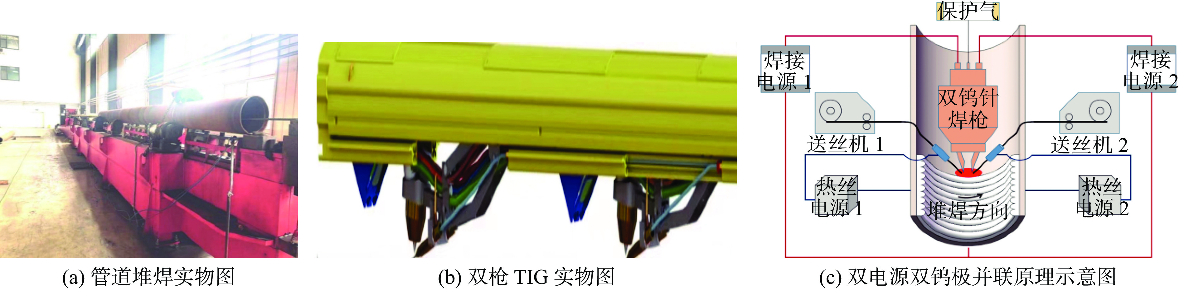
图 1 堆焊过程实物图和示意图
Figure 1. Physical drawings and schematic drawings of surfacing welding process. (a) photo of pipeline cladding application; (b) photo of dual-torch TIG welding system; (c) schematic diagram of dual-power dual-tungsten parallel configuration
![]()
图 2 Inconel 625堆焊层横截面微观形貌
Figure 2. Cross-section microstructure morphology of Ni/steel surfacing plates. (a) as-welded state; (b) solution treatment at 800 ℃; (c) solution treatment at 900 ℃
![]()
图 3 镍基合金堆焊层微观组织形貌
Figure 3. Enlarged view on microstructure morphology of Ni-based alloy surfacing layers. (a) as-welded state; (b) solution treatment at 800 ℃; (c) solution treatment at 900 ℃
![]()
图 4 镍基合金堆焊层形貌及局部放大
Figure 4. Morphologies and corresponding local magnified image in the nickel-based alloy surfacing layer. (a) as-welded state; (b) solution treatment at 800 ℃; (c) solution treatment at 900 ℃; (d) Fig. 4(a) magnified view; (e) Fig. 4(b) magnified view; (f) Fig. 4(c) magnified view
![]()
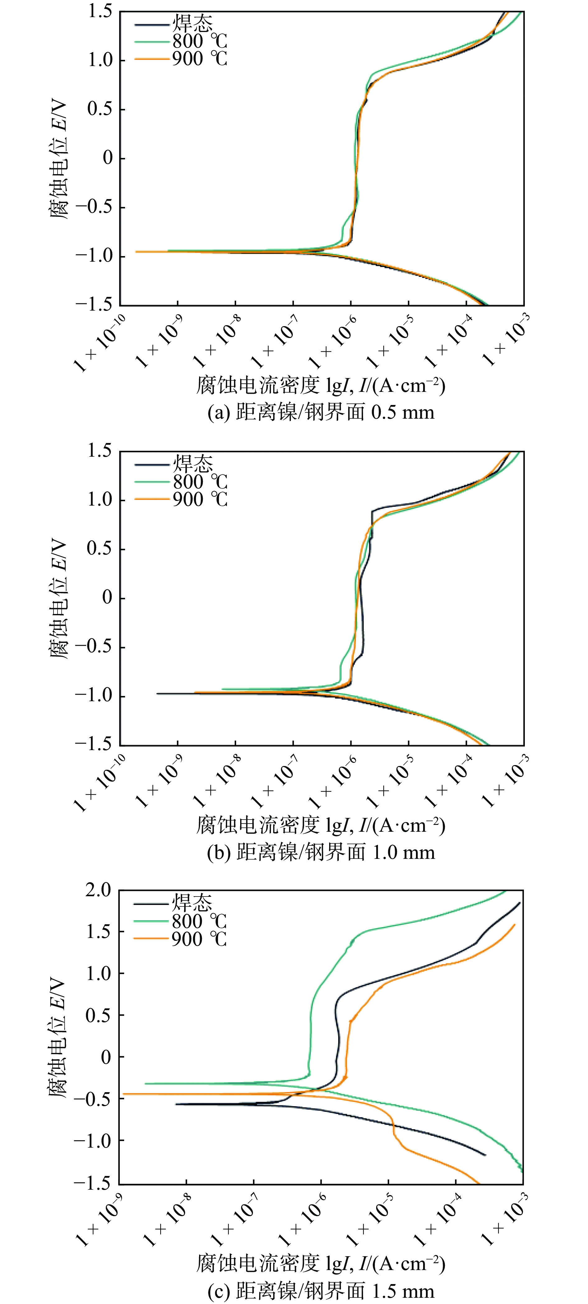
图 6 不同样品在3.5%NaCl溶液中的电化学极化曲线
Figure 6. Potential dynamic polarization curves of different specimens at 3.5%NaCl solution. (a) located at 0.5 mm away from the Ni/steel interface; (b) located at 1.0 mm away from the Ni/steel interface; (c) located at 1.5 mm away from the Ni/steel interface
![]()
图 7 不同试样在3.5%NaCl溶液中的Nyquist图
Figure 7. Nyquist diagram of different samples in 3.5%NaCl solution. (a) located at 0.5 mm away from the Ni/steel interface; (b) located at 1.0 mm away from the Ni/steel interface; (c) located at 1.5 mm away from the Ni/steel interface
![]()
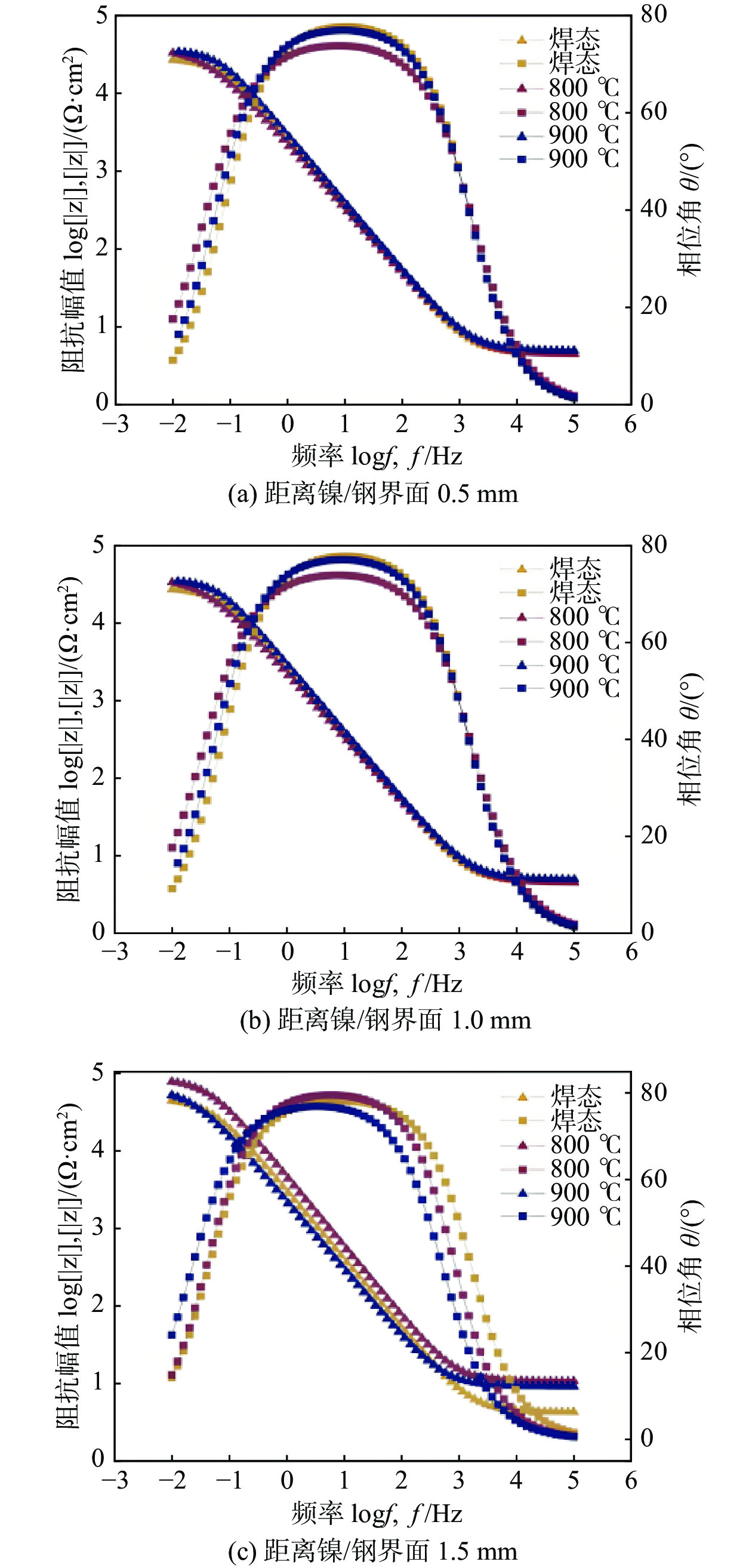
图 8 不同试样在3.5%NaCl溶液中的Bode图
Figure 8. Bode diagram of different samples in 3.5%NaCl solution. (a) located at 0.5 mm away from the Ni/steel interface; (b) located at 1.0 mm away from the Ni/steel interface; (c) located at 1.5 mm away from the Ni/steel interface
![]()
图 9 堆焊层EIS 拟合采用的等效电路
Figure 9. Equivalent circuit used for surfacing layer EIS fitting
![]()
图 10 距镍/钢界面0.5 mm试样表面钝化膜 XPS 总谱图
Figure 10. XPS analysis total spectrum of passivation film on the surface of the sample located at 0.5mm away from the Ni/steel interface
![]()
图 11 镍基合金堆焊层的钝化膜中主要元素XPS图谱
Figure 11. XPS spectra of main elements in the passivation film of Ni-based alloy surfacing layer. (a) O1s; (b) Nb3d; (c) Cr2p; (d) Fe2p; (e) Mo3d; (f) Ni2p
表 1 Gr.B级钢和ERNiCrMo-3焊丝的化学成分(质量分数,%)
Table 1 Chemical composition of Gr.B steel and ERNiCrMo-3 welding wire
材料 C Si Mn Ni Cr Mo Fe Nb Al Ti Gr.B 0.190 0 0.250 0.400 0.04 0.01 0.003 余量 0.004 — 0.002 ERNiCrMo-3 0.009 3 0.026 0.012 余量 22.18 9.080 0.101 3.730 0.2 0.300  下载: 导出CSV
表 2 镍基合金堆焊层中特征点能谱分析(质量分数,%)
Table 2 Energy spectrum analysis results of characteristic points in nickel-based alloy surfacing layer
特征点 Ni Cr Nb Fe Mo Ti C A 43.27 16.05 10.19 19.42 7.02 4.05 — B 11.89 2.92 67.03 6.93 — 0.11 11.12 C 58.32 17.93 8.83 7.29 7.35 0.28 —
下载: 导出CSV
表 3 不同试样腐蚀电位及腐蚀电流密度
Table 3 Corrosion potential and corrosion current density of different specimens
镍基合金堆焊层 腐蚀电位
Ecorr /V腐蚀电流密度
Icorr /(10−7A·cm−2)焊态—0.5 mm −0.969 13 4.592 3 800 ℃—0.5 mm −0.940 06 3.854 3 900 ℃—0.5 mm −0.955 25 4.334 3 焊态—1.0 mm −0.951 06 5.234 7 800 ℃—1.0 mm −0.898 00 4.091 3 900 ℃—1.0 mm −0.931 12 5.086 6 焊态—1.5mm −0.547 06 1.995 9 800 ℃—1.5mm −0.300 25 1.432 5 900 ℃—1.5mm −0.423 06 3.189 1
下载: 导出CSV
表 4 不同试样电化学阻抗谱拟合数据
Table 4 Data of different samples were fitted by electrochemical impedance spectroscopy
试样 溶液电阻Rs/(Ω·cm2) 恒相元
CPEQf/
(10−5Ω−1·cm2·Ω-n)CPE弥散
指数
n电荷转
移电阻
Rf/(Ω·cm2)焊态—0.5 mm 4.596 6.941 2 0.879 41 28 092 800 ℃—0.5 mm 4.486 9.485 9 0.833 45 38 204 900 ℃—0.5 mm 4.968 6.936 3 0.869 85 36 496 焊态—1.0 mm 4.876 8.434 8 0.854 74 35 972 800 ℃—1.0 mm 4.689 8.808 7 0.844 61 50 409 900 ℃—1.0 mm 4.25 7.419 3 0.872 43 42 254 焊态—1.5 mm 4.227 6.700 5 0.881 55 46 124 800 ℃—1.5 mm 10.57 4.207 5 0.899 31 80 719 900 ℃—1.5 mm 9.047 9.291 1 0.870 82 60 404
下载: 导出CSV
-
[1] YU Xin , NIU Ruixia , ZHANG Li, et al. The effect of CaCO3 deposit on corrosion of NaCl-Alkali/ surfactant/ polymer produced water pipeline[J]. Materials Chemistry and Physics, 2022, 290: 126665.
[2] 安乾鹏, 王天龙, 秦向发. 石油管道的防腐现状及解决对策[J]. 化工设计通讯, 2019, 45(10): 26 − 27. doi: 10.3969/j.issn.1003-6490.2019.10.019 AN Qianpeng, WANG Tianlong, QIN Xiangfa. Corrosion prevention of petroleum pipelines and countermeasures[J]. Chemical Engineering Design Communication, 2019, 45(10): 26 − 27. doi: 10.3969/j.issn.1003-6490.2019.10.019
[3] YUAN Juntao , TIAN Lu , ZHU Wenxu , et al. Internal localized corrosion of X65-grade crude oil pipeline caused by the synergy of deposits and microorganisms[J]. Engineering Failure Analysis, 2023, 149: 107276.
[4] HOJAT Jafari, IMAN Danaee, HADI Eskandari. Combined computational and experimental study on the adsorption and inhibition effects of N2O2 schiff base on the corrosion of API 5L grade B steel in 1 mol/L HCl[J]. Journal of Materials Science & Technology, 2014, 30(3): 23 − 25.
[5] STUART Bell, MITCHELL de Bruyn, TED Steinberg, et al. Corrosion resistance of 625 nickel superalloy exposed to isothermal and thermal cycling conditions in a chloride/carbonate salt[J]. Solar Energy, 2023, 249: 278 − 287. doi: 10.1016/j.solener.2022.11.034
[6] WANG Huhe , LI Xiaojie , WANG Yuxin , et al. Microstructural evolution and interfacial properties of explosively welded Nb/steel composite plate during post-heat treatment[J]. Journal of Materials Research and Technology, 2023, 25: 7376 − 7388.
[7] FENG Kangkang , ZHANG Biao , SHEN Xiaolong , et al. Research on the influence of differential speed ratio on the microstructure and properties of 316L/Ni/EH40 composite plate by asymmetrical rolling[J]. Materials Today Communications, 2023, 37: 107431.
[8] PU Juan, SUN Yubo, WU Lei, et al. Effect of CeO2 content on microstructure and properties of Ni-based tungsten carbide layer by plasma arc cladding[J]. Coatings, 2022, 12(3): 342. doi: 10.3390/coatings12030342
[9] SU Ziyi , MASAHIRO Masaki, MASAHIRO Nishida, et al. Characteristics of ejecta resulting from hypervelocity impact on Al/Mg explosive welding clad materials[J]. International Journal of Impact Engineering, 2024, 186: 104869.
[10] CAI Yuan , SUN Huanteng , CAI Qingshan , et al. Effect of hot rolling on microstructure and mechanical properties of hot isostatically pressed 30CrMnSiNi2A ultrahigh strength steel[J]. Materials Science and Engineering: A, 2024, 891: 145956.
[11] ABIOYE T E, FARAYIBI P K. Effect of carbide dissolution on the corrosion performance of tungsten carbide reinforced Inconel 625 wire laser coating[J]. Journal of Materials Processing Technology, 2016, 231: 89 − 99. doi: 10.1016/j.jmatprotec.2015.12.023
[12] CHAUDHURI A, RAGHUPATHY Y, SRINIVASAN D. Microstructural evolution of cold-sprayed Inconel 625 superalloy coatings on low alloy steel substrate[J]. Acta Materialia, 2017, 129: 11 − 25. doi: 10.1016/j.actamat.2017.02.070
[13] MANDINA M, MAGNASCO M, ZAPPAVIGNA G. The electro-slag cladding process: application, main metallurgical and testing issues in the fabrication of reactors in large thickness 2 1/4Cr–1Mo–1/4V[J]. China Welding, 2014, 28(5): 380 − 396.
[14] SING M, BHAGI L K, ARORA H. Effects of shielded metal arc welding process parameters on dilution in hard facing of mild steel using factorial design[J]. Advanced Materials, 2020, 32: 207 − 220.
[15] SINGHAL T S, JAIN J K. GMAW cladding on metals to impart anti-corrosiveness: Machine, processes and materials[J]. Materials Today Proceedings, 2020, 26(2): 32 − 41.
[16] WANG Junyan , CUI Xiufang , JIN Guo , et al. Effect of in-situ Ni interlayer on the microstructure and corrosion resistance of underwater wet 316L stainless steel laser cladding layer[J]. Surface and Coatings Technology, 2023, 458: 129341.
[17] AMAN Singh, VIVEK Singh, AJAY Pratap Singh, et al. Experiment analysis of A-TIG welding and comparison between TIG, Double-TIG, and A-TIG of Hastelloy C-276[J]. Materials Today: Proceedings, 2023, 100: 102 − 107.
[18] ACHMAD Ariaseta, ABDUL Khaliq Khan, JOEL Andersson, et al. Microstructural study of keyhole TIG welded nickel-based superalloy G27[J]. Materials Characterization, 2023, 204: 113178. doi: 10.1016/j.matchar.2023.113178
[19] KOBAYASHI K , YUKI M, TEJIMA A, et al. Development of high efficiency TIG welding method (SEDAR-TIG)[J]. Ishikawajima-Harima Giho, 2002, 42: 32 − 42.
[20] 冷雪松, 张广军, 吴林. 双钨极氩弧焊耦合电弧压力分析[J]. 焊接学报, 2006, 27(9): 13 − 16. doi: 10.3321/j.issn:0253-360X.2006.09.004 LENG Xuesong, ZHANG Guangjun, WU Lin. Analysis of coupled arc pressure in double tungsten-argon arc welding[J]. Transactions of the China Welding Institution, 2006, 27(9): 13 − 16. doi: 10.3321/j.issn:0253-360X.2006.09.004
[21] 王新鑫, 樊丁, 黄健康, 等. 双钨极耦合电弧数值模拟[J]. 物理学报, 2013, 62(22): 412 − 421. doi: 10.7498/aps.62.228101 WANG Xinxin, FAN Ding, HUANG Jiankang, et al. Numerical simulation of double tungsten arc coupling[J]. Acta Physica Sinica, 2013, 62(22): 412 − 421. doi: 10.7498/aps.62.228101
[22] 乔小丽, 曹帅, 武靖伟, 等. Inconel 600镍基合金PAW + TIG接头微观组织及力学性能[J]. 焊接学报, 2019, 45(6): 105 − 112. QIAO Xiaoli, CAO Shuai, WU Jingwei, et al. Microstructure and mechanical properties of PAW + TIG joint of Inconel 600 nickel-based alloy[J]. Transactions of the China Welding Institution,, 2019, 45(6): 105 − 112.
[23] 王诗洋, 刘士伟, 侯星宇, 等. 焊丝成分对镍基高温合金TIG焊焊接性的影响[J]. 焊接学报, 2019, 44(3): 31 − 36,60. WANG Shiyang, LIU Shiwei, HOU Xingyu, et al. Effect of wire composition on weldability of nickel based superalloy in TIG welding[J]. Transactions of the China Welding Institution, 2019, 44(3): 31 − 36,60.
[24] PU Juan, LI Zhipeng, HU Qingxian, et al. Effect of heat treatment on microstructure and wear resistance of high manganese steel surfacing layer[J]. International Jourmal of Moder Physics B, 2019, 33: 1 − 3.
[25] PU Juan, XIE Peng, LONG Weimin, et al. Effect of current on corrosion resistance of duplex stainless-steel layer obtained by plasma arc cladding[J]. Crystals, 2022, 12(3): 61 − 64.
[26] HE Kun , DONG Lijin , WANG Qinying , et al. Comparison on the microstructure and corrosion behavior of Inconel 625 cladding deposited by tungsten inert gas and cold metal transfer process[J]. Surface and Coatings Technology, 2022, 435: 375 − 380.
[27] Wang J, Zhang J G, Zhang Z M, et al. Boosting soot combustion efficiency of Co3O4 nanocrystals via tailoring crystal facets[J]. Chemical Engineering Journal, 2018, 337: 488 − 498. doi: 10.1016/j.cej.2017.12.141
[28] ZHANG C, WANG J G, YANG S F, et al. Boosting total oxidation of acetone over spinel MCo2O4(M = Co, Ni, Cu) hollow mesoporous spheres by cation-substituting effect[J]. Journal of Colloid and Interface Science, 2019, 539: 65 − 75.
[29] BAKARE M S, VOISEY K T, ROE M J , et al. X-ray photoelectron study of the passive films formed on thermally sprayed and wrought Inconel 625[J]. Applied Surface Science, 2010, 257(3): 786 − 794.
[30] 史鹏, 吕仙姿, 张杰, 等. 镍基合金CMSX-4在3.5% NaCl溶液中的腐蚀行为[J]. 广西科学院学报, 2020, 36(4): 427 − 433. SHI Peng, LYU Xianzi, ZHANG Jie, et al. Corrosion behavior of nickel base alloy CMSX-4 in 3.5% NaCl solution[J]. Journal of Guangxi Academy of Sciences, 2020, 36(4): 427 − 433.
[31] ZHANG Yuan, ZHANG Xian, CHEN Siyu , et al. Corrosion behavior and passive film properties of nickel-based alloy in phosphoric acid[J]. Corrosion Communications, 2023, 9: 77 − 88.
-
期刊类型引用(1)
1. 张德龙,张宏乐,王宇凯,赵彦军,田锦涛,杜春峰. 重型结构件智能焊接工艺及参数优化研究与应用. 中国机械. 2023(32): 38-41+45 .  百度学术
百度学术
其他类型引用(1)


计量
- 文章访问数: 28
- HTML全文浏览量: 6
- PDF下载量: 13
- 被引次数: 2
