Research progress on micro/nano joining technologies and failure behaviors in electronic packaging
-
摘要: 微纳连接技术是电子封装中的关键技术,近年来,随着电子产品逐渐小型化、轻量化的方向发展,各种先进的微纳连接层出不穷,但仍缺少系统的归纳及总结. 文中对引线键合技术,熔化微连接技术、软钎焊技术、纳米焊膏烧结技术、导电胶连接技术、表面活化键合技术及新兴的纳米连接技术等具有代表性的微纳连接技术进行了综述,并针对软钎焊焊点在热载荷、电载荷、机械载荷及多物理场耦合作用下微互连的失效行为研究进行了总结. 结果表明,未来的微纳连接技术将朝向互连尺寸更加微小,互连方法逐渐智能化,互连材料更加绿色,互连焊点更可靠的方向发展. 软钎焊互连焊点的失效行为分析也将逐渐从单一热场、电场载荷的研究拓展至热—电—力多物理场耦合载荷,与实际工况更加贴合,随着如同步辐射,三维X射线等先进表征技术的不断发展,失效行为及机制的研究也将更加精准.Abstract: Micro/nano joining are the key technologies in electronic packaging. With the development of electronic products in the direction of miniaturization and lightweight, various advanced micro/nano joining techniques have emerged in an endless flow, but there is still a lack of systematic summary. In this paper, the representative micro-nano bonding technologies are reviewed, including wire bonding, melting micro-bonding, soldering, nano-paste sintering, conductive adhesive bonding, surface-activated bonding and emerging nano joining technology. The failure behaviors of solder joints under thermal, electrical, mechanical and multi-physics coupling load are summarized. In the future, the micro/nano joining technology will be developed in the direction of smaller interconnect size, intelligent interconnect method, green interconnect material and more reliable interconnect solder joint. The failure behavior analysis of solder joints will gradually expand from the study of single load to thermo-electric-mechanical multiple physical field coupling load, which is more suitable for the actual working conditions. With the continuous development of advanced characterization technologies such as synchrotron radiation and 3D X-ray, the study of failure behaviors and mechanisms will also be more accurate.
-
Keywords:
- electronic packaging /
- micro/nano joining /
- failure behavior /
- reliability /
- multiple field coupling
-
0. 序言
焊接是轨道车辆关键结构连接的主要工艺,作为一种新型熔化焊方法,激光填丝焊因具有变形小、焊缝成形好、缺陷少以及接头力学性能高等优点,近年来已备受车体结构焊接的青睐[1-2]. Q310NQL2-Q345NQR2耐候钢激光焊对接接头作为轨道车辆部分关键结构连接常用的接头形式,其在服役运行过程中经常承受复杂的动态载荷,进而引发突然性的疲劳断裂,因此其服役过程的疲劳失效一直是领域内关注的重点问题.
目前焊接接头的抗疲劳设计重点关注接头的疲劳极限和疲劳寿命评估[3-4],传统的疲劳极限评估方法主要为升降法,而疲劳寿命评估则较多采用成组法完成,这些方法不仅历时长、成本高[5-11],而且结果往往依赖于经验性的数据统计,因而在很大程度上限制了产品性能测试的速度以及研发效率的提升.疲劳实际上是材料内微观结构在循环载荷状态下朝着损伤累积和失效方向逐渐演化的过程,这一过程表现为耗散能的持续释放,同时伴随着热力学的温升响应变化[12]. 随着热像技术发展的日趋成熟,使得借助红外热像仪精确获取疲劳过程的三阶段温升响应成为可能,进而为构建物理意义更为明确的能量耗散模型奠定基础.
国内外学者以能量耗散为基础做了大量的疲劳研究工作,Fan等人[13-14]以Q235钢为研究对象,建立了一种可实现快速预测宏微观疲劳行为的能量耗散模型,基于此模型测定了Q235钢高周疲劳过程的能量耗散,并与其损伤变量建立了函数关系,进而对其疲劳极限进行了快速评估;Teng等人[15]结合RVE(representataive volume element)模型,进一步优化了Fan等人建立的能量耗散模型,并对SAE 1045钢的宏微观疲劳行为进行了快速预测评估; Yang等人[16-17]进一步研发了与微结构运动相关的能量耗散模型,该模型将滞弹性和非弹性行为的分界点作为疲劳极限预测的特征点,实现了FV520B钢疲劳极限的快速预测;Guo等人[18-20]基于一维热传导方程,推导了一种新的能量耗散计算方法,该方法以平均温升为基础参量,可最大程度上减小计算误差,为发展精确的能量耗散计算模型奠定了基础. 然而上述相关模型依赖的基础参量为第二阶段的温升增量,该参量往往需要大量的时间测得;此外上述研究主要针对非焊接金属材料展开,对于非均质焊接接头疲劳研究虽有涉及[5-11, 21-23],但其能量耗散模型尚未与疲劳过程的微结构行为建立紧密联系.
为了实现快速、精确的焊接接头疲劳性能评估,以Q310NQL2-Q345NQR2激光焊对接接头为研究对象,以第一阶段的初始温升斜率为基础,结合ISV模型,以期建立一种与焊接接头高周疲劳过程微结构运动联系紧密的能量耗散模型,进而为实现从能量耗散角度出发快速评估疲劳性能奠定基础.
1. 基于ISV理论的本构模型
从热动力学的角度来讲,Hemholtz自由能是状态函数,其值可以通过获取当前的状态变量计算得到,考虑在热弹性范围内,Hemholtz自由能有如下定义[24],即
$$ \psi = \psi ({\boldsymbol{\varepsilon }},T) $$ (1) 式中:
$\psi $ 为自由能;ε 和T分别为应变张量和绝对温度,是决定状态函数的观测状态变量. 从式(1)可以看出,在弹性尺度内,当ε 和T两个观测状态变量(observable state variable, OSV)确定时,其相关状态函数的值也随之确定. 当材料的变形行为更为复杂时,即其变形存在不完全弹性的情况,例如滞弹性和微塑性,往往必须扩展内部状态变量(ISV)实现独立定义现有的热力学状态函数[24].疲劳是一个伴随着温升演化的不可逆热力学过程, 为精确描述疲劳过程中的热力学状态变化,实现对包含非弹性的力学行为表征,这里引入α和β 两个ISV变量, 因此式(1)可以表示为[24]
$$ \psi (T,{\boldsymbol{\varepsilon }},{\boldsymbol{\alpha }},{\boldsymbol{\beta }}) = u - Ts $$ (2) 式中: T, ε, u和s分别为绝对温度、应变张量、内能以及熵流,此外ISV变量α 代表着与可恢复微结构运动相关的滞弹性行为,例如应力驱动的原子振荡和晶界处的内摩擦,而变量β 则表示不可恢复微结构运动相关的微塑性行为,进而引起材料内部的损伤(图1),这里α 和β 可以定义为
$$ \left\{\begin{gathered} {\boldsymbol{\alpha }} = ({\alpha _1},{\alpha _2},\cdots,{\alpha _i},\cdots,{\alpha _m}) \\ {\boldsymbol{\beta }} = ({\beta _1},{\beta _2},\cdots,{\beta _j},\cdots,{\beta _n}) \\ \end{gathered} \right.$$ (3) 2. 能量耗散模型
根据热力学第一定律,疲劳过程的热平衡方程可以表示为[19]
$$ \rho C\dot T + {\text{div}}{{{J}}_{\text{q}}} = {d_1} + {\theta _{{\text{the}}}} + {\theta _{{\text{inc}}}} + {r_{\text{e}}} $$ (4) 式中: ρ和C分别为焊缝材料密度和比热;
${{J}}_{\text{q}} $ 为热流;d1,θthe,θinc和re分别表示为$$ {d_1}{\text{ = }}\left(\sigma {{ - }}\rho \frac{{\partial \psi }}{{\partial \varepsilon }}\right) \cdot {{\boldsymbol {\boldsymbol{\varepsilon}} }} - \rho \frac{{\partial \psi }}{{\partial \alpha }} \cdot {{ {\boldsymbol{\alpha}} }} - \rho \frac{{\partial \psi }}{{\partial \beta }} \cdot {{ {\boldsymbol{\beta}} }} $$ (5) $$ {\theta _{{\text{the}}}} = \rho T\frac{{{\partial ^2}\psi }}{{\partial T\partial \varepsilon }} \cdot {{\boldsymbol {\boldsymbol{\varepsilon}} }} $$ (6) $$ {\theta _{{\text{ic}}}} = \rho T\frac{{{\partial ^2}\psi }}{{\partial T\partial \alpha }} \cdot {{ {\boldsymbol{\alpha}} }} $$ (7) 根据文献[24],可以推导得到
$$ \sigma = \rho \frac{{\partial \psi }}{{\partial \varepsilon }} $$ (8) 将式(8)代入式(5),d1可以表示为
$$ {d_1}{\text{ = }} - \rho \frac{{\partial \psi }}{{\partial \alpha }} \cdot {{\boldsymbol \alpha }} - \rho \frac{{\partial \psi }}{{\partial \beta }} \cdot {{\boldsymbol \beta }} $$ (9) 式中:
$- \rho \dfrac{{\partial \psi }}{{\partial \alpha }} $ 和$- \rho \dfrac{{\partial \psi }}{{\partial \beta }} $ 为与内部变量α 和β 相关的热力学共轭矢量,其被认为是驱动材料内部达到热力学平衡状态的非平衡力,这里将其分别定义为A和B,得到$$ {d_1}{\text{ = }}{\boldsymbol{A}} \cdot {{\boldsymbol \alpha }} + {\boldsymbol{{ B}}} \cdot {{\boldsymbol \beta }} $$ (10) 式中:α 和β 为与微结构运动相关的内变量变化率,通常被视为广义热力学通量,由非平衡力A和B决定. 这里出于简化目的,假设广义热力学通量α 和β 与非平衡力A和B之间的关系服从线性或比例关系,这个假设对于正在经历高周疲劳过程的材料来说是非常合理的,因为其仅是在平衡状态附近波动,即接近一个准静态平衡过程[25],即
$$ \left\{\begin{gathered} {{\boldsymbol \alpha }} = {m_{\rm{an}}}{\boldsymbol{A}} \\ {{\boldsymbol \beta }} = {m_{\rm{in}}}{\boldsymbol{B}} \\ \end{gathered} \right.$$ (11) 式中:
${m_{\rm{an}}}$ 和${m_{\rm{in}}}$ 是独立于热力学通量和非平衡驱动力的材料常数. 将式(11)带入式(10),得到$$ {d_1} = {m_{\rm{an}}}{\left\| {\boldsymbol{A}} \right\|^2} + {m_{\rm{in}}}{\left\| {\boldsymbol{ B}} \right\|^2} $$ (12) 式中:||•||表示矢量的欧几里得范数. 从式(12)可以看出,d1由两部分组成,即一部分由滞弹性引导的能量耗散dan(不构成损伤),而另外一部分则是与非弹性行为相关的能量耗散(引起疲劳损伤增加)din,式(12)变形为
$$ {d_1}{\text{ = }}{d_{{\text{an}}}}{\text{ + }}{d_{{\text{in}}}}{\text{ = }}{{m_{{\rm{an}}}}}{\left\| {\boldsymbol{A}} \right\|^2} + {{m_{{\rm{in}}}}}{\left\| {\boldsymbol{ B}} \right\|^2} $$ (13) 对于疲劳过程来说,与材料微结构运动相关的非平衡力A和B与外加载荷以及频率有关,因此这里假设||A||2和||B||2与应力幅和频率有如下关系,即
$$ \left\{ \begin{gathered} {\left\| {\boldsymbol{A}} \right\|^2} = \left[ {{u_{{\text{an}}}}({\sigma _{\text{a}}} - {\sigma _{\text{0}}})} \right]\left[ {H({\sigma _{\text{a}}} - {\sigma _{{\text{c0}}}})} \right] \\ {\left\| {\boldsymbol{B}} \right\|^2} = ({u_{{\text{in}}}}{\sigma _{\text{a}}}^kf)\left[ {H({\sigma _{\text{a}}} - {\sigma _{{\text{c1}}}})} \right] \\ \end{gathered}\right. $$ (14) 式中:H(x)为海维赛德阶跃函数(heaviside step function),即当x≥0时,H(x)=1,当x<0时,H(x)=0;k为幂指数;uan和uin为比例系数;σc0和σc1为与材料微结构运动状态相关的两个特征应力幅值;
${\sigma _{\text{a}}} $ 为应力幅. 将式(14)代入式(13),得到$$ {d_1} = \left\{ \begin{array}{l} {d_{{\rm{an}}}} = \left[ {{F_{{\rm{an}}}}({\sigma _{\rm{a}}} - {\sigma _{{\rm{c0}}}})} \right],{\sigma _{{\rm{c0}}}} < {\sigma _{\rm{a}}} < {\sigma _{{\rm{c1}}}}\\ {d_{{\rm{an}}}} + {d_{{\rm{in}}}} = \left[ {{F_{{\rm{an}}}}({\sigma _{\rm{a}}} - {\sigma _{{\rm{c0}}}})} \right] + {F_{{\rm{in}}}}{\sigma _{\rm{a}}}^k,{\sigma _{{\rm{c1}}}} < {\sigma _{\rm{a}}} \end{array} \right. $$ (15) 式中:Fan(=man uan f ),Fin(=min uin f ),k,σc0以及σc1可以通过试验测定.
3. 疲劳寿命预测模型
3.1 能量耗散响应
疲劳过程的温升进程由3个阶段组成[5],分别为初始加载的温度迅速增加阶段(Ⅰ)、热产和热耗散实现平衡的稳定温升阶段(Ⅱ)以及因裂纹扩展引起的温升陡然变化阶段(Ⅲ),如图2所示.
对于高周疲劳过程,其某一应力水平下的能量耗散计算式为[26]
$$ {d_1}{\text{ = }}{\left. {\rho C\frac{{{\text{d}}T}}{{{\text{d}}t}}} \right|_{t = {t_0}}} $$ (16) 式中:
${\dfrac{{\rm{d}}T}{{\rm{d}}t} }$ 为温度变化率;t0为初始加载时间.如第2节所述,高周疲劳过程的机械能耗散主要由滞弹性和非弹性行为引起[19],其中当应力幅小于焊接接头的疲劳极限时,其微结构运动主要为可恢复的滞弹性行为,例如轻微的原子振荡或内摩擦,不构成损伤累积;而当应力幅高于焊接接头的疲劳极限时,其微结构运动主要为不可恢复的非弹性行为,例如微塑性,构成接头内部的损伤[5]. 基于此,将疲劳过程中对接接头在不同应力幅水平下微结构运动的分界点定义为疲劳极限,具有明确的物理意义.
为了从宏观热力学角度量化微观尺度内的接头微结构运动行为,在第1节里引入了ISV内变量理论,并分别定义了与滞弹性和非弹性相关的内变量α 和β,进而推导得到了高周疲劳过程的能量耗散计算表达式. 结合第2节建立的能量耗散模型,疲劳过程中不同应力幅水平下的能量耗散响应示意图如图3所示.
3.2 基于损伤累积的疲劳寿命预测模型
如第1节所述,ISV里的内变量β与引导疲劳损伤累积的不可恢复微结构运动相关,而该疲劳损伤的演化正由内部非平衡力B驱动,并在宏观尺度上表现为非弹性耗散din,因此非弹性耗散din可被视为有效的疲劳损伤指标. 基于此可建立相应的累积损伤评估模型,即
$$ D = \frac{{N{F_{{\rm{in}}}}\sigma _{\text{a}}^k}}{{{{\bar E}_{\text{c}}}}}\left[ {H({\sigma _{\text{a}}} - {\sigma _{{\text{c}}1}})} \right] $$ (17) 式中:D为损伤参数;N为与损伤参量D对应的疲劳寿命;
$\bar {E}_{\rm{c}} $ 为能量耗散临界值,其值可以通过试验测定. 对于一个原始试样来说,其损伤值D可认为是0,当载荷逐渐循环直至疲劳断裂出时,D=1,因此式(17)变形为$$ {N_{\text{f}}} = \frac{{{{\bar E}_{\text{c}}}}}{{{F_{{\rm{in}}}}\sigma _{\text{a}}^k}}\left[ {{H^{ - 1}}({\sigma _{\text{a}}} - {\sigma _{{\text{c}}1}})} \right] $$ (18) 式中:H −1(x)为海维赛德阶跃函数的倒数,即当x≥0时,H −1(x)=1,而当x<0时,H −1(x)=∞. 这里需要注意的是,当σa<σc1时,认为对接接头试样拥有无限寿命,因此依据提出的模型,关键应力幅σc1实际上可以被认为是材料内部可恢复和不可恢复微结构运动的分界应力幅,即σc1等于疲劳极限σf.
通过监测试样焊缝中心的温升增量,建立能量耗散模型,进而结合式(18)即可实现Q310NQL2-Q345NQR2激光焊对接接头的疲劳寿命快速预测.
4. 试验方法
4.1 试验材料
采用激光填丝焊对2.5 mm板厚的Q310NQL2耐候钢和4 mm板厚的Q345NQR2耐候钢进行焊接,激光器功率为6 kW的光纤激光器,焊丝为ER50-G,送丝设备选用数字化送丝结构. 焊接过程中,填充焊丝位于激光之前,激光与试板垂线的夹角为10°,保护气体为氩气,坡口形式为I形(全焊透),激光焊接过程示意图如图4所示. Q310NQL2耐候钢、Q345NQR2耐候钢、ER50-G焊丝的化学成分以及力学性能见表1和表2所示. Q310NQL2-Q345NQR2激光焊对接接头尺寸如图5所示.
表 1 Q310NQL2和Q345NQR2耐候钢以及ER50-G焊丝主要化学成分Table 1. Main chemical composition of Q310NQL2, Q345NQR2 weathering steel, and ER50-G filler wire材料 C Si Mn P S Cu Cr Ni Ti Fe Q310NQL2 ≤0.12 0.25 ~ 0.75 0.20 ~ 0.50 0.06 ~ 0.12 ≤0.02 0.25 ~ 0.50 0.30 ~ 1.25 0.12 ~ 0.65 — 余量 Q345NQR2 ≤0.12 0.25 ~ 0.75 ≤1.0 0.06 ~ 0.15 ≤0.02 0.25 ~ 0.50 0.30 ~ 1.25 0.12 ~ 0.65 — 余量 ER50-G ≤0.10 ≤0.60 0.90 ~ 1.30 ≤0.025 ≤0.02 0.20 ~ 0.50 0.30 ~ 0.90 0.20 ~ 0.60 — 余量 表 2 Q310NQL2和Q345NQR2耐候钢以及ER50-G焊丝力学性能Table 2. Mechanical propertie parameters of Q310NQL2, Q345NQR2 weathering steel, and ER50-G filler wire材料 屈服强度
ReL/MPa抗拉强度
Rm/MPa断后伸长率
A(%)Q310NQL2 ≥310 480 ~ 670 ≥22 Q345NQR2 ≥345 490 ~ 675 ≥22 ER-50G ≥400 ≥500 ≥22 4.2 疲劳试验与热像测试
根据国家标准GB/T 3075—2008《金属材料 疲劳试验 轴向力控制方法》在PLG-100型疲劳试验机上对Q310NQL2-Q345NQR2对接接头进行疲劳测试(图6),试验频率为106 Hz,载荷形式采用单轴、正弦变化的动态载荷,应力比(R=σmin/σmax)取0.1. 选用Fluke Ti450红外热像仪对焊缝中心疲劳过程的温升响应进行全程监测,其采集图像的频率为9 Hz. 疲劳试验热像测试具体试验步骤如下.
(1) 借助热像仪监测对接接头焊缝中心在不同应力幅水平下(σa=99.5~171 MPa)的初始阶段温升斜率,结合式(16)计算不同应力幅水平的能量耗散.
(2) 结合建立的能量耗散模型,计算得到不同应力幅下的能量耗散响应,进而测定Fan , Fin,k,σc0以及σc1(疲劳极限)等参数.
(3) 进行恒幅疲劳测试获取能量耗散临界值
${\bar E}_{\rm{c}} $ .5. 试验结果
5.1 不同应力幅下的能量耗散响应分析
根据第2节建立的能量耗散模型,结合式(16)计算了不同应力幅下的能量耗散值,如图7所示. 结合式(15),采用最小二乘法对试验数据实现了较好的拟合,并对σc0,σc1,Fan,Fin以及k等参数进行了确定(表3).
表 3 能量耗散模型参数Table 3. Parameters of energy disspation modelσc0 σc1 Fan Fin k 65 126 4.7 × 10⁻² 8.20 × 10⁻²³ 10.18 从图7中可以看出,随着应力水平的增加,能量耗散值随之增加,且在第一类关键应力(σc0=65 MPa)和第二类关键应力(σc1=126 MPa,即疲劳极限)之间,其能量耗散与应力幅的依赖程度几乎是线性的;而当应力幅值超过第二类关键应力σc1时,其不同应力幅下的能量耗散响应关系呈现为非线性趋势,这与前述模型所述一致(图3). 结合建立的能量耗散模型(式(15))对试验数据拟合,拟合的决策系数R2为0.97,这表明能量耗散模型与试验数据的一致性较高,这种较高的一致性源于两种不同的微结构演化机制,如3.1节所述,当应力幅等级介于σc0和σc1之间,其微结构运动主要为可恢复的滞弹性行为,例如轻微的原子振荡或内摩擦,因此在该阶段其能量耗散的响应几乎是线性的;而当应力幅等级高于σc1(即疲劳极限)时,由于不可逆微塑性行为的出现,且占该阶段微结构运动的绝大部分,使得其能量耗散响应急剧增加,且呈现为非线性的特点.
$${d_1}{\rm{ = }}\left\{ \begin{array}{l} {d_{{\rm{an}}}} = \left[ {0.047 ({\sigma _{\rm{a}}} - 65)} \right],\quad 65 < {\sigma _{\rm{a}}} < 126\\ {d_{{\rm{an}}}}{\rm{ + }}{d_{{\rm{in}}}} = \left[ {0.047 ({\sigma _{\rm{a}}} - 65)} \right]+\\ \qquad\qquad 8.20 \times {10^{ - 23}} {\sigma _{\rm{a}}}^{10.18},\quad {\sigma _{\rm{a}}} > 126 \end{array} \right.$$ (19) 5.2 基于能量耗散的疲劳寿命预测
如3.3节所述,疲劳过程中的能量耗散存在临界值Ec, 因此结合图3和式(19),对应力幅为148.5 MPa下与不可逆微结构运动相关的能量耗散临界值进行了计算,可确定
${\bar E}_{\rm{c}}$ 为1.35 × 10⁵ J/m3. 从图8中可以看出,试样的不可逆能量耗散值基本分布在平均值加减一个标准差的范围内,这表明该临界值几乎是一个常数,与文献报道的结果一致[17].基于试验测定的能量耗散临界值
${\bar E}_{\rm{c}} $ ,结合3.3节建立能量耗散模型(式(18))对Q310NQL2-Q345NQR2对接接头的疲劳寿命进行了快速预测,如图9所示,拟合方法为最小二乘法. 从图9中可以看出,两条拟合S-N曲线非常接近,其中经预测数据拟合的S-N曲线斜率和截距为−10.18和27.22,而经试验数据拟合的S-N曲线的斜率和截距为−10.78和28.52,其相对误差值分别为5.54%和4.77%,均小于10%,从而验证了提出模型具有较高的精度. 因此在试样有限的情况下,结合建立的能量耗散模型,获取其不同应力等级下的能量耗散响应情况,继而可实现Q310NQL2-Q345NQR2对接接头的疲劳寿命快速预测评估. 值得指出的是,尽管该模型对于Q310NQL2-Q345NQR2对接接头的疲劳性能具有较好的预测能力,但是其对于其它类型接头的适用性还需要在接下来的工作中进一步验证.6. 结论
(1)结合ISV理论的本构模型,提出了一种新的基于能量耗散理论的对接接头高周疲劳寿命快速预测模型.
(2)模型引入了两个关键应力幅,并将其与可恢复微结构运动(滞弹性)和不可恢复微结构运动(非弹性)开始形成的关键应力幅σc0和σc1(疲劳极限)建立了紧密关系,阐明了疲劳过程中的微结构运动的物理意义.
(3)基于建立的疲劳寿命预测模型,对Q310NQL2-Q345NQR2对接接头的疲劳进行了快速预测,并借助预测数据对其S-N曲线进行了拟合,结果表明,经预测数据和试验数据拟合的中值S-N曲线非常接近,其斜率和截距误差仅为5.54%和4.77%,从而验证了提出模型的有效性.
-
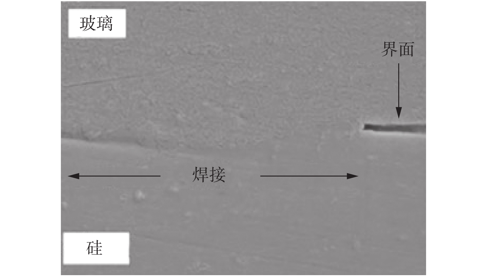
图 2 激光焊连接玻璃和硅微观形貌[13]
Figure 2. Microstructure of bonded glass and silicon by laser joining
图 3 微电阻连接铝丝与镀金铜焊盘微观形貌[19]
Figure 3. Microstructure of bonded Al wire with gold plated copper pad by micro-resistance welding
图 4 电流辅助全IMC焊点的微观形貌[27]
Figure 4. Microstructure of full-IMC solder joint assisted by electric current
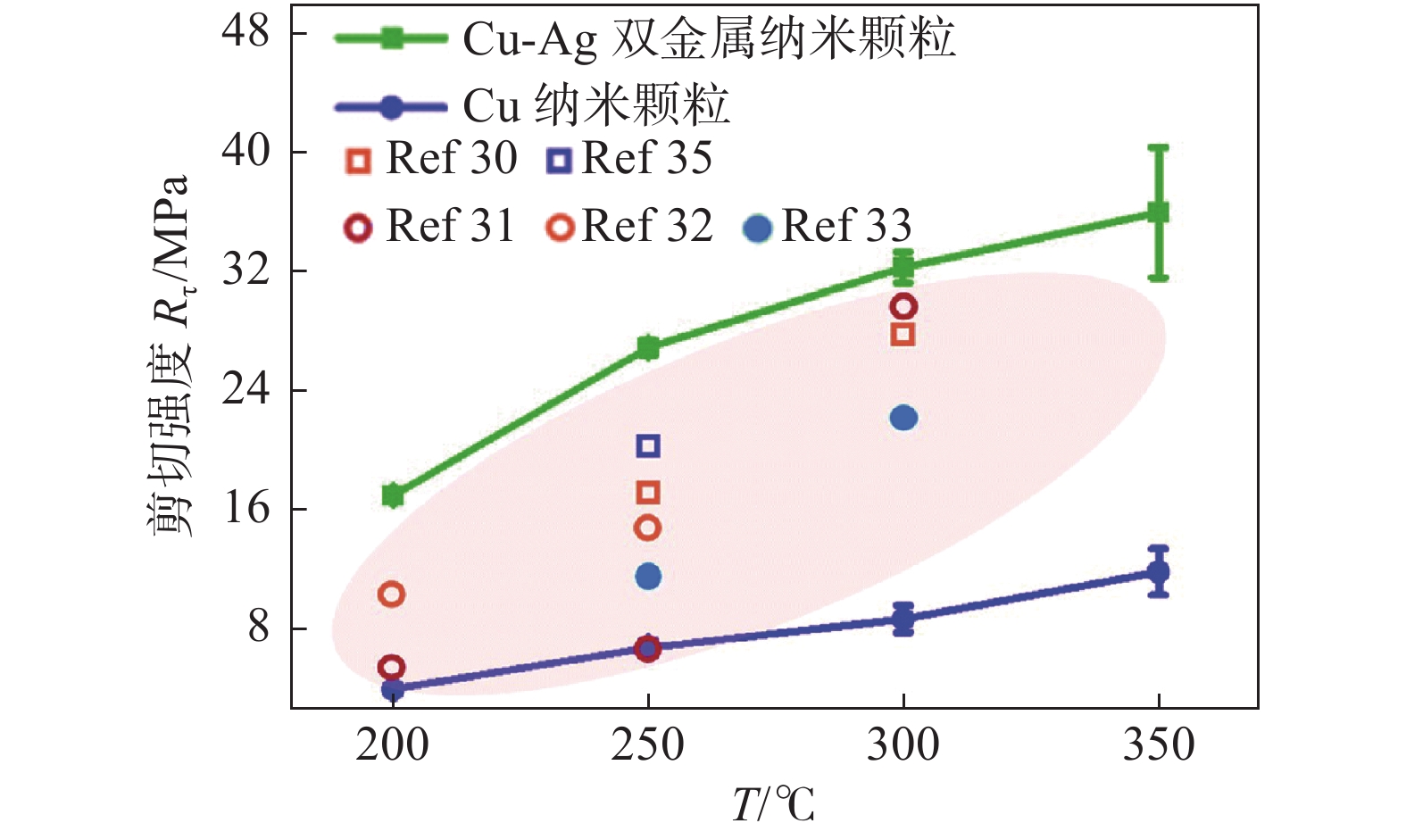
图 5 Cu/Cu@Ag纳米焊膏/Cu三明治焊点抗剪强度[31]
Figure 5. Shear strength of sintered Cu/Cu@Ag nanopaste/Cu sandwich joint
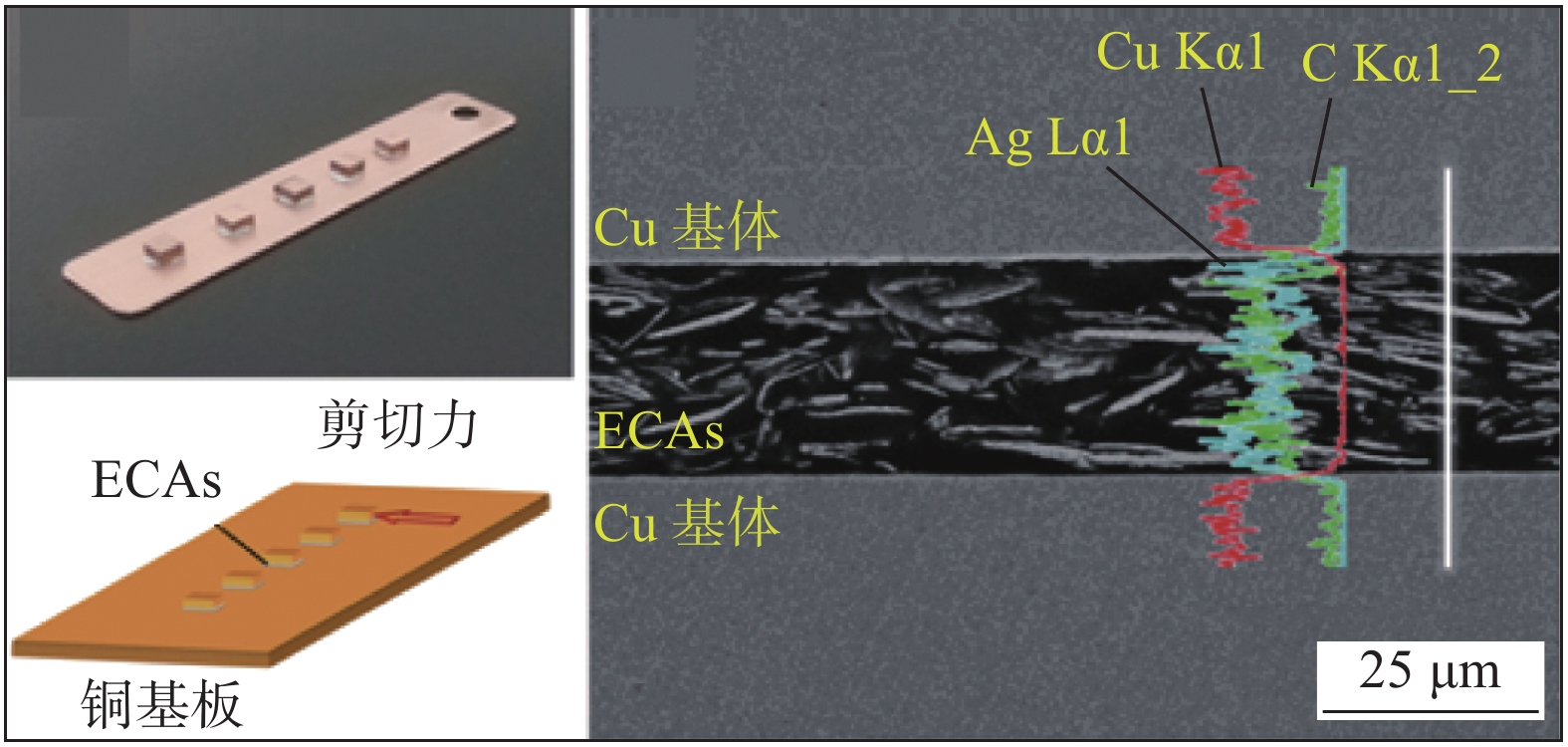
图 6 聚苯胺改性的各向同性导电胶连接Cu-Cu焊盘的微观结构[42]
Figure 6. Microstructure of Cu-Cu pad joined by polyaniline modified isotropic conductive adhesive
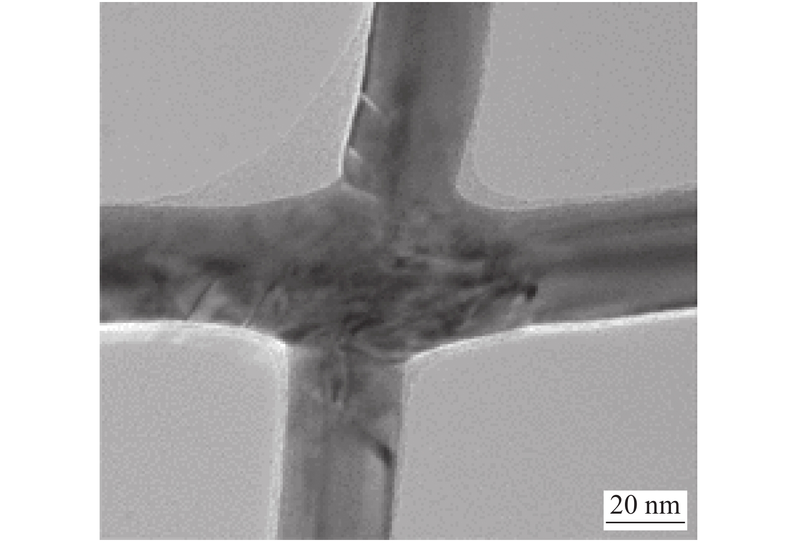
图 7 自限制纳米钎焊连接银纳米线[52]
Figure 7. Joining of silver nanowires by self-limited nanosoldering
图 8 添加氧化石墨烯前后的仿真[53]
Figure 8. Simulation before and after adding graphene oxide
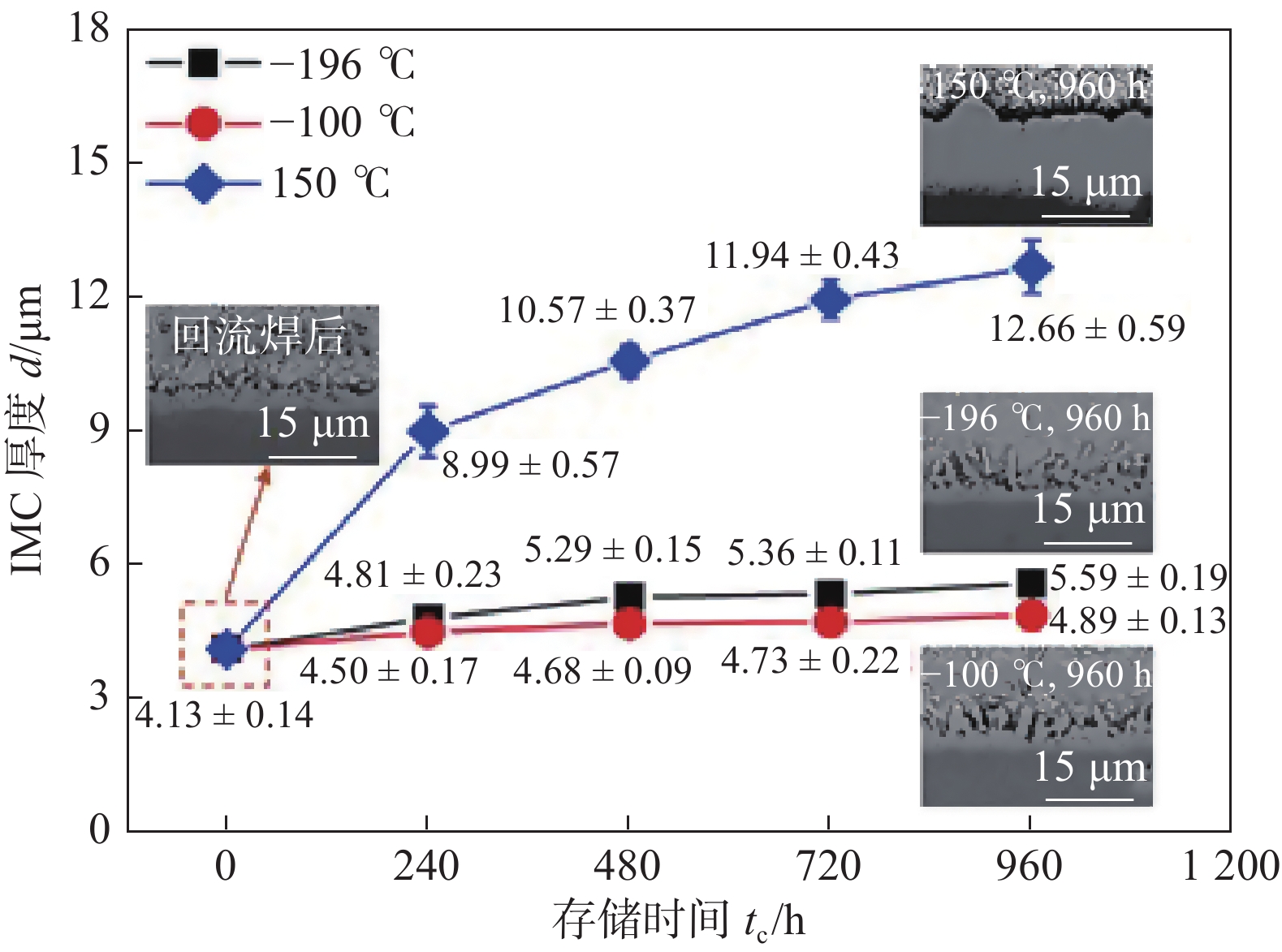
图 9 不同温度下贮存不同时间IMC厚度变化[57]
Figure 9. Variation of IMC thickness after storing at different time at different temperature
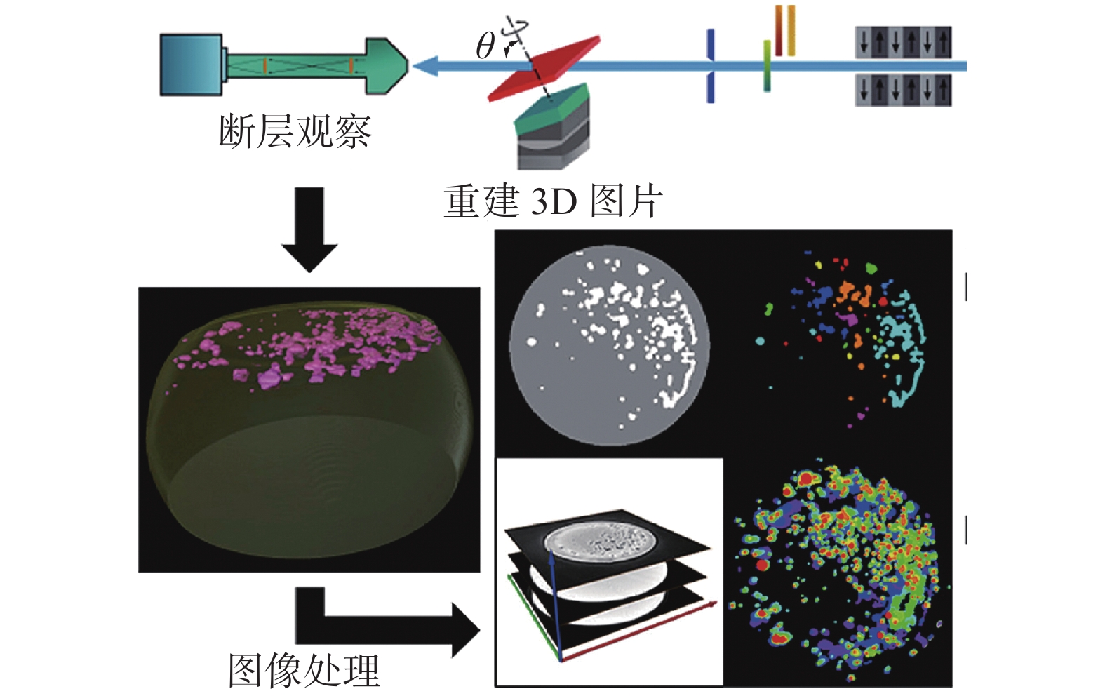
图 10 焊点电迁移失效行为[59]
Figure 10. Failure behavior of solder joints under electromigration
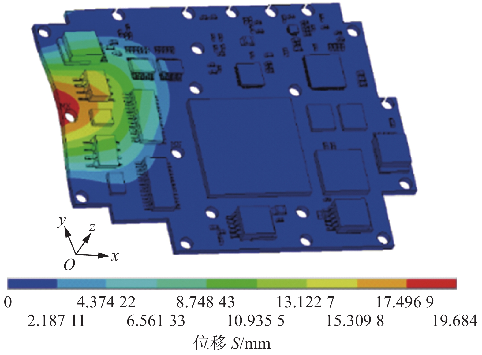
图 11 机械固定对应力分布的影响[64]
Figure 11. Effect of fixation on stress distribution
-
[1] Tummala R. Fundamentals of microsystems packaging[M]. New York: McGraw-Hill Professional, 2001.
[2] Kaimori S, Nonaka T, Mizogucgi A. The development of Cu bonding wire with oxidation-resistant metal coating[J]. IEEE Transactions on Advanced Packaging, 2006, 29: 227 − 231. doi: 10.1109/TADVP.2006.872999
[3] 王星星, 上官林健, 何鹏, 等. 基于熵模型镀锡银钎料钎焊性能的定量表征[J]. 焊接学报, 2020, 41(1): 18 − 22. Wang Xingxing, Shangguan Linjian, He Peng, et al. Quantitative characterization of brazability for Sn-plated Ag brazing filler metals based on entropy model devices[J]. Transactions of the China Welding Institution, 2020, 41(1): 18 − 22.
[4] 杨婉春, 王帅, 祝温泊, 等. 低温烧结纳米铜焊膏的制备及其连接性能分析[J]. 焊接学报, 2018, 39(6): 72 − 76. doi: 10.12073/j.hjxb.2018390152 Yang Wanchun, Wang Shuai, Zhu Wenbo, et al. Preparation and connection performance analysis of solder paste by low-temperature sintering Cu nanoparticles[J]. Transactions of the China Welding Institution, 2018, 39(6): 72 − 76. doi: 10.12073/j.hjxb.2018390152
[5] Hu A, Jolanta JR, Sano T. Joining technology innovations at the macro, micro, and nano levels[J]. Applied Sciences, 2019, 9(17): 3568. doi: 10.3390/app9173568
[6] 邹贵生, 闫剑峰, 母凤文. 微连接和纳连接的研究新进展[J]. 焊接学报, 2011, 32(4): 107 − 112,118. Zou Guisheng, Yan Jianfeng, Mu Fengwen, et al. Recent progress in microjoining and nanojoining[J]. Transactions of The China Welding Institution, 2011, 32(4): 107 − 112,118.
[7] Chen M, Zhang Y, Guo Y, et al. Research on flip-chip bonding process and thermal cycle reliability simulation of 3-D stacked structure[J]. IEEE Transactions on Componentrs Packaging and Manufacturing Technology, 2022, 12(1): 51 − 58. doi: 10.1109/TCPMT.2021.3127157
[8] Che F, Wai L, Chai T. Failure mode and mechanism analysis for Cu wire bond on Cu/low-k chip by wire pull test and finite-element analysis[J]. IEEE Transactions on Device and Materials Reliability, 2018, 18: 163 − 172. doi: 10.1109/TDMR.2018.2808348
[9] 邹军, 谢昶. 多芯片组件中金丝金带键合互连的特性比较[J]. 微波学报, 2010, 26(增刊): 378 − 380. Zou Jun, Xie Chang. Recent progress in microjoining and nanojoining[J]. Journal of Microwaves, 2010, 26(supplement): 378 − 380.
[10] 王尚, 王凯枫, 张贺, 等. 射频器件超细引线键合工艺及性能研究[J]. 机械工程学报, 2021, 57(22): 201 − 208. doi: 10.3901/JME.2021.22.201 Wang Shang, Wang Kaifeng, Zhang He, et al. Study on ultrafine wire bonding and performance of radio frequency devices[J]. Journal of Mechanical Engineering, 2021, 57(22): 201 − 208. doi: 10.3901/JME.2021.22.201
[11] 王尚, 马竟轩, 杨东升, 等. 射频器件超细引线键合射频性能仿真[J]. 焊接学报, 2021, 42(10): 1 − 7. Wang Shang, Ma Jingxuan, Yang Dongsheng, et al. Research on the RF performance simulation of ultra-fine wire bonding of RF devices[J]. Transactions of the China Welding Institution, 2021, 42(10): 1 − 7.
[12] Norrdin I H W, Okamoto Y, Okada A, et al. Effect of focusing condition on molten area characteristics in micro-welding of borosilicate glass by picosecond pulsed laser[J]. Applied Physics, A. Materials Science & Processing, 2016, 122(5): 492.
[13] 程战, 郭伟, 刘磊, 等. 石英玻璃与硅的飞秒激光微连接及其接头性能研究[J]. 中国激光, 2015, 42(9): 225 − 231. Cheng Zhan, Guo Wei, Liu Lei, et al. Mechanical properties of microweld of silica glass to silicon by femtosecond laser[J]. Chinese Journal of Laser, 2015, 42(9): 225 − 231.
[14] Huang Y D, Pequegnat A, Zou G S, et al. Crossed-wire laser microwelding of Pt-10 Pct Ir to 316 LVM stainless steel: Part II. effect of orientation on joining mechanism[J]. Metallurgical and Materials Transactions A-Physical Metallurgy and Materials Science, 2012, 43A: 1234 − 1243.
[15] Zou G, Huang Y, Pequegnat A, et al. Crossed-wire laser microwelding of Pt-10 Pct Ir to 316 low-carbon vacuum melted stainless steel: Part I. mechanism of joint formation[J]. Metallurgical and Materials Transactions A-Physical Metallurgy and Materials Science, 2012, 43A: 1223 − 1233.
[16] 陈伟彦, 张延松. 太阳能电池互连片平行间隙电阻焊工艺优化[J]. 机械设计与研究, 2019, 35(5): 75 − 79. doi: 10.13952/j.cnki.jofmdr.2019.0279 Chen Weiyan, Zhang Yansong. Study on process optimization of parallel gap resistance welding of solar cell and interconnector based on temperature field analysis[J]. Machine Design and Research, 2019, 35(5): 75 − 79. doi: 10.13952/j.cnki.jofmdr.2019.0279
[17] Zhang W, Cong S, Wen Z, et al. Experiments and reliability research on bonding process of micron copper wire and nanometer gold layer[J]. The International Journal of Advanced Manufacturing Technology, 2017, 92: 4073 − 4080. doi: 10.1007/s00170-017-0490-z
[18] Zhang H, Wang S, Wu B, et al. Ultrafast parallel micro-gap resistance welding of an AuNi9 microwire and Au microlayer[J]. Micromachines, 2021, 12(1): 51. doi: 10.3390/mi12010051
[19] Wang S, Zhang H, Li Y, et al. Phase transformation behavior of Al-Au-Cu intermetallic compounds under ultra-fast micro resistance bonding process[J]. Materials Characterization, 2021, 180: 111401. doi: 10.1016/j.matchar.2021.111401
[20] Cong S, Zhang W, Zhang H, et al. Growth kinetics of (Cu xNi1- x)6Sn5 intermetallic compound at the interface of mixed Sn63Pb37/SAC305 BGA solder joints during thermal aging test[J]. Materials Research Express, 2021, 8: 106301. doi: 10.1088/2053-1591/ac3168
[21] Rajendran S, Jung D, Jung J. Investigating the physical, mechanical, and reliability study of high entropy alloy reinforced Sn-3.0Ag-0.5Cu solder using 1608 chip capacitor/ENIG joints[J]. Journal of Materials Science: Materials in Electronics, 2022, 33: 3687 − 3710. doi: 10.1007/s10854-021-07562-2
[22] Tian Y, Wang C, Zhang X, et al. Interaction kinetics between PBGA solder balls and Au/Ni/Cu metallisation during laser reflow bumping[J]. Soldering & Surface Mount Technology, 2003, 15(2): 17 − 21.
[23] Tian Y, Wang C. Formation and change of AuSn4 compounds at interface between PBGA solder ball and Au/Ni/Cu metallization during laser and infrared reflow soldering[J]. Acta Metallurgica Sinica (English Letters), 2004, 17(2): 199 − 204.
[24] Yao P, Li X, Liang X B, et al. Investigation of soldering process and interfacial microstructure evolution for the formation of full Cu3Sn joints in electronic packaging[J]. Materials Science in Semiconductor Processing, 2017, 58: 39 − 50. doi: 10.1016/j.mssp.2016.11.019
[25] Li M, Li Z, Xiao Y, et al. Rapid formation of Cu/Cu3Sn/Cu joints using ultrasonic bonding process at ambient temperature[J]. Applied Physics Letters, 2013, 102(9): 094104. doi: 10.1063/1.4794684
[26] Feng J, Hang C, Tian Y, et al. Effect of electric current on grain orientation and mechanical properties of Cu-Sn intermetallic compounds joints[J]. Journal of Alloys and Compounds, 2018, 753: 203 − 211. doi: 10.1016/j.jallcom.2018.04.041
[27] Liu B, Tian Y, Wang C, et al. Ultrafast formation of unidirectional and reliable Cu3Sn-based intermetallic joints assisted by electric current[J]. Intermetallics, 2017, 80: 26 − 32. doi: 10.1016/j.intermet.2016.10.004
[28] Liu B, Tian Y, Feng J, et al. Enhanced shear strength of Cu–Sn intermetallic interconnects with interlocking dendrites under fluxless electric current-assisted bonding process[J]. Journal of Materials Science, 2017, 52: 1943 − 1954. doi: 10.1007/s10853-016-0483-6
[29] Schwarzbauer H, Kuhnert R. Novel large area joining technique for improved power device performance[J]. IEEE Transactions on Industry Applications, 1991, 27(1): 93 − 95. doi: 10.1109/28.67536
[30] Dai Y, Ng M, Anantha P, et al. Enhanced copper micro/nano-particle mixed paste sintered at low temperature for 3D interconnects[J]. Applied Physics Letters, 2016, 108: 263103. doi: 10.1063/1.4954966
[31] Tian Y, Jiang Z, Wang C, et al. Sintering mechanism of the Cu–Ag core–shell nanoparticle paste at low temperature in ambient air[J]. RSC Advances, 2016, 6: 91783 − 91790. doi: 10.1039/C6RA16474A
[32] Liu X, Liu W, Wang C, et al. Optimization and modeling for one-step synthesis process of Ag-Cu nano-particles using DOE methodology[J]. Journal of Materials Science: Materials in Electronics, 2016, 27: 4265 − 4274. doi: 10.1007/s10854-016-4292-0
[33] Zhong Y, An R, Wang C, et al. Low temperature sintering Cu6Sn5 nanoparticles for superplastic and super-uniform high temperature circuit interconnections[J]. Small, 2015, 11: 4097 − 4103. doi: 10.1002/smll.201500896
[34] Guo L, Liu W, Ji X, et al. Facile synthesis of Cu10Sn3 nanoparticles and their sintering behavior for power device packaging[J]. Results in Materials, 2021, 10: 100187. doi: 10.1016/j.rinma.2021.100187
[35] Jia Q, Zou G, Zhang H, et al. Sintering mechanism of Ag-Pd nanoalloy film for power electronic packaging[J]. Applied Surface Science, 2021, 554: 149579. doi: 10.1016/j.apsusc.2021.149579
[36] 付善灿. 纳米银焊膏无压低温烧结连接方法的绝缘栅双极型晶体管(IGBT)模块封装应用研究[D]. 天津: 天津大学, 2016. Fu Shancan. Research on application of insulated gate bipolar transistor (IGBT) module fabrication by pressureless low temperature sintering of nanosilver paste[D]. Tianjin: Tianjin University, 2016.
[37] Zhang Z, Chen C, Suetake, et al. Pressureless and low-temperature sinter-joining on bare Si, SiC and GaN by a Ag flake paste[J]. Scripta Materialia, 2021, 198: 113833. doi: 10.1016/j.scriptamat.2021.113833
[38] 黄圆, 杭春进, 田艳红, 等. 纳米铜银核壳焊膏脉冲电流快速烧结连接铜基板研究[J]. 机械工程学报, 2019, 55(24): 51 − 56. doi: 10.3901/JME.2019.24.051 Huang Yuang, Hang Chunjin, Tian Yanhong, et al. Rapid sintering of nano copper-silver core-shell paste and interconnection of copper substrates by pulse current[J]. Journal of Mechanical Engineering, 2019, 55(24): 51 − 56. doi: 10.3901/JME.2019.24.051
[39] Ji H, Zhou J, Liang M, et al. Ultra-low temperature sintering of Cu@Ag core-shell nanoparticle paste by ultrasonic in air for high-temperature power device packaging[J]. Ultrasonics Sonochemistry, 2018, 41: 375 − 381. doi: 10.1016/j.ultsonch.2017.10.003
[40] Liu W, Wang Y, Zheng Z, et al. Laser sintering mechanism and shear performance of Cu-Ag-Cu joints with mixed bimodal size Ag nanoparticles[J]. Journal of Materials Science: Materials in Electronics, 2019, 30: 7787 − 7793. doi: 10.1007/s10854-019-01094-6
[41] Liu H, Ma R, Zhao D, et al. Application of silver nanoparticles in electrically conductive adhesives with silver micro flakes[J]. China Welding, 2022, 31(2): 23 − 28.
[42] Wen J, Tian Y, Hang C, et al. Fabrication of novel printable electrically conductive adhesives (ECAs) with excellent conductivity and stability enhanced by the addition of polyaniline nanoparticles[J]. Nanomaterials, 2019, 9(7): 960. doi: 10.3390/nano9070960
[43] Cao G, Cui H, Wang L, et al. Highly conductive and highly dispersed polythiophene nanoparticles for fabricating high-performance conductive adhesives[J]. ACS Applied Electronic Materials, 2020, 2: 2750 − 2759. doi: 10.1021/acsaelm.0c00457
[44] 马跃辉. PS/金属核壳结构复合微球的制备及其在各向异性导电胶膜上的应用[D]. 上海: 东华大学, 2013. Ma Yuehui. Preparation of polystyrene/metal core/shell microspheres and their application in anisotropic conductive film[D]. Shanghai: Donghua University, 2013.
[45] 王正家. ACA互连的多因素作用分析与性能优化[D]. 武汉: 华中科技大学, 2010. Wang Zhengjia. Analysis of anisotropic conductive adhesive interconnection under multi-factors influence and optimization for its performance [D]. Wuhan: Huazhong University of Science and Technology, 2010.
[46] 陈显才. 倒装键合中各向异性导电胶微互连电阻形成机理研究[D]. 武汉: 华中科技大学, 2012. Chen Xiancai. The research on the formation mechanism of micro ACA joints resistance in the flip chip bonding[D]. Wuhan: Huazhong University of Science and Technology, 2012.
[47] Bo G, Yu H, Ren L, et al. Gallium-indium-tin liquid metal nanodroplet-based anisotropic conductive adhesives for flexible integrated electronics[J]. ACS Applied Nano Materials, 2021, 4: 550 − 557. doi: 10.1021/acsanm.0c02870
[48] Wang C, Wang Y, Tian Y, et al. Room-temperature direct bonding of silicon and quartz glass wafers[J]. Applied Physics Letters, 2017, 110: 221602. doi: 10.1063/1.4985130
[49] 张贺, 王尚, 冯佳运, 等. 金属/非金属纳米线连接及应用研究进展[J]. 机械工程学报, 2022, 58(2): 76 − 87. Zhang He, Wang Shang, Feng Jiayun, et al. Recent progress of metal/nonmetal nanowire joining technology and its applications[J]. Journal of Mechanical Engineering, 2022, 58(2): 76 − 87.
[50] Lin L, Liu L, Peng P, et al. In situ nanojoining of Y- and T-shaped silver nanowires structures using femtosecond laser radiation[J]. Nanotechnology, 2016, 27: 125201. doi: 10.1088/0957-4484/27/12/125201
[51] Zhang H, Tian Y, Wang S, et al. Highly stable flexible transparent electrode via rapid electrodeposition coating of Ag-Au alloy on copper nanowires for bifunctional electrochromic and supercapacitor device[J]. Chemical Engineering Journal, 2020, 399(20): 125075.
[52] Huang Y, Tian Y, Hang C, et al. Self-limited nanosoldering of silver nanowires for high-performance flexible transparent heaters[J]. ACS Applied Materials & Interfaces, 2019, 11: 21850 − 21858.
[53] Ding S, Zhang S, Tong X, et al. Room-temperature nanojoining of silver nanowires by graphene oxide for highly conductive flexible transparent electrodes[J]. Nanotechnology, 2022, 34: 045201.
[54] Gao L, Liu Z, Li C. Failure mechanisms of SAC/Fe-Ni solder joints during thermal cycling[J]. Journal of Electronic Materials, 2017, 46: 5338 − 5348. doi: 10.1007/s11664-017-5554-1
[55] Mattila T, Kivilahti J. The role of recrystallization in the failure of SnAgCu solder interconnections under thermomechanical loading[J]. IEEE Transactions on Components and Packaging Technologies, 2010, 33: 629 − 635. doi: 10.1109/TCAPT.2010.2051268
[56] Ji X, An Q, Xia Y, et al. Maximum shear stress-controlled uniaxial tensile deformation and fracture mechanisms and constitutive relations of Sn-Pb eutectic alloy at cryogenic temperatures[J]. Materials Science and Engineering: A, 2021, 819: 141523. doi: 10.1016/j.msea.2021.141523
[57] Tian R, Hang C, Tian Y, et al. Interfacial intermetallic compound growth in Sn-3Ag-0.5Cu/Cu solder joints induced by stress gradient at cryogenic temperatures[J]. Journal of Alloys and Compounds, 2019, 800: 180 − 190. doi: 10.1016/j.jallcom.2019.05.295
[58] Chen C, Tong H, Tu K. Electromigration and thermomigration in Pb-Free flip-chip solder joints[J]. Annual Review of Materials Research, 2010, 40: 531 − 555. doi: 10.1146/annurev.matsci.38.060407.130253
[59] Chang Y, Cheng Y, Xu F, et al. Study of electromigration-induced formation of discrete voids in flip-chip solder joints by in-situ 3D laminography observation and finite-element modeling[J]. Acta Materialia, 2016, 117: 100 − 110. doi: 10.1016/j.actamat.2016.06.059
[60] Liu B, Tian Y, Qin J, et al. Degradation behaviors of micro ball grid array (μBGA) solder joints under the coupled effects of electromigration and thermal stress[J]. Journal of Materials Science: Materials in Electronics, 2016, 27: 11583 − 11592. doi: 10.1007/s10854-016-5289-4
[61] Luan J, Tee T, Pek E, et al. Dynamic responses and solder joint reliability under board level drop test[J]. Microelectronics Reliability, 2007, 47: 450 − 460. doi: 10.1016/j.microrel.2006.05.012
[62] Marjamaki P, Mattila T T, Kivilahti J K. A comparative study of the failure mechanisms encountered in drop and large amplitude vibration tests[C]//56th Electronic Components and Technology Conference 2006. San Diego, CA, USA, 2006: 95-101.
[63] Liu F, Meng G. Random vibration reliability of BGA lead-free solder joint[J]. Microelectronics Reliability, 2014, 54: 226 − 232. doi: 10.1016/j.microrel.2013.08.020
[64] 李跃, 田艳红, 丛森, 等. PCB组装板多器件焊点疲劳寿命跨尺度有限元计算[J]. 机械工程学报, 2019, 55(6): 54 − 60. doi: 10.3901/JME.2019.06.054 Li Yue, Tian Yanhong, Cong Sen, et al. Multi-scale finite element analysis into fatigue lives of various component solder joints on printed circuit board[J]. Journal of Mechanical Engineering, 2019, 55(6): 54 − 60. doi: 10.3901/JME.2019.06.054
[65] Feng D, Wang F, Li D, et al. Atomic migration on Cu in Sn-58Bi solder from the interaction between electromigration and thermomigration[J]. Materials Research Express, 2019, 6: 046301. doi: 10.1088/2053-1591/aaf91c
[66] Ye H, Basaran C, Hopkins D. Thermomigration in Pb-Sn solder joints under joule heating during electric current stressing[J]. Applied Physics Letters, 2003, 82: 1045 − 1047. doi: 10.1063/1.1554775
[67] 李望云. 电-热-力耦合场作用下无铅微焊点的变形和断裂行为及其尺寸效应研究[D]. 广州: 华南理工大学, 2017. Li Wangyun. Deformation and fracture behavior of microscale lead-free solder joints under electro-thermo-mechanical coupled loads and their size effects[D]. Guangzhou: South China University of Technology, 2017.
[68] 李胜利, 任春雄, 杭春进, 等. 极端热冲击和电流密度耦合Sn-3.0Ag-0.5Cu焊点组织演变[J]. 机械工程学报, 2022, 58(2): 291 − 299. doi: 10.3901/JME.2022.02.291 Li Shengli, Ren Chunxiong, Hang Chunjin, et al. Microstructure evolution of Sn-3.0Ag-0.5Cu solder joints under extreme temperature changes and current stressing[J]. Journal of Mechanical Engineering, 2022, 58(2): 291 − 299. doi: 10.3901/JME.2022.02.291
-
期刊类型引用(1)
1. 吴泽兵,周珂飞,郭龙龙,赵海超,邓勇拓,张文超,郑维新. 焊接顺序对角接接头残余应力和变形的影响. 热加工工艺. 2021(13): 150-154+158 .  百度学术
百度学术
其他类型引用(1)


 下载:
下载:


