
Formability, microstructure and mechanical properties of nano-treated Al-Zn-Mg-Cu alloy fabricated by wire arc additive manufacturing
-
摘要:
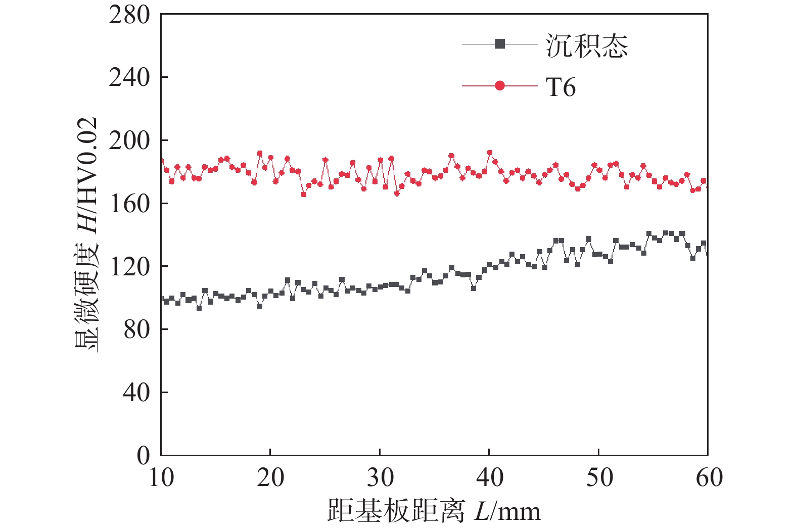
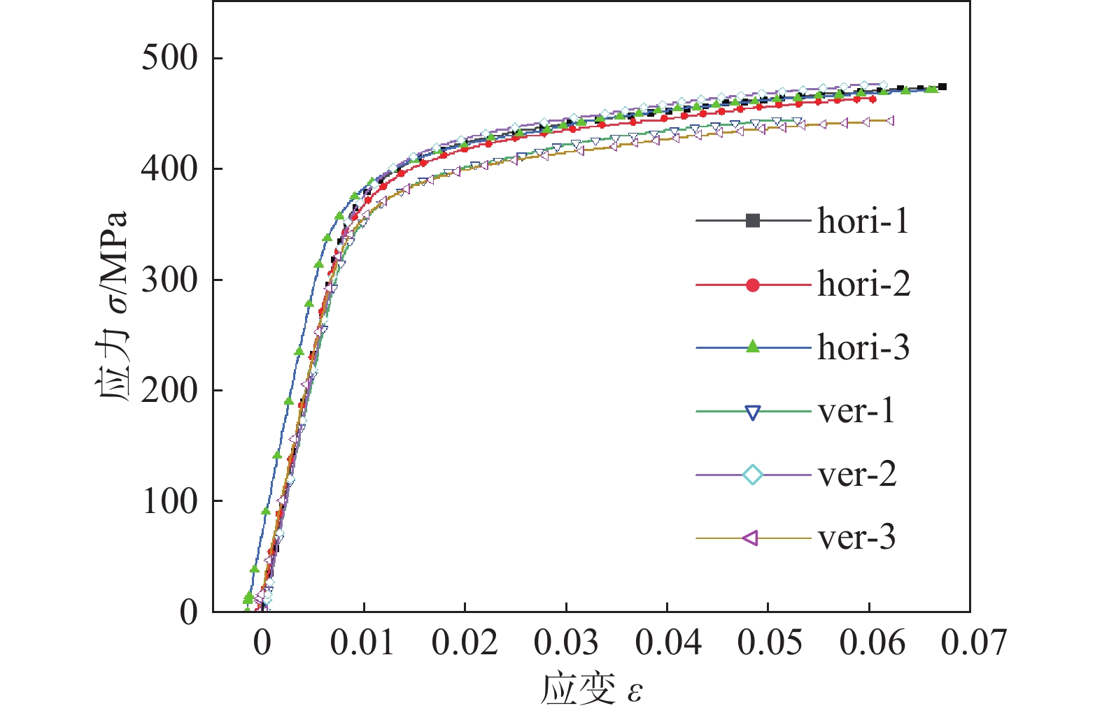
采用电弧熔丝增材制造技术(WAAM)对纳米改性Al-Zn-Mg-Cu 合金进行成形试验,分析了焊接电流、焊接速度、沉积路径、层间等待时间对成形性能的影响. 结果表明,在焊接电流190 A、焊接速度350 mm/min、往复沉积、层间等待时间为90 s时合金具有良好的成形性能. 对制备的直壁墙体进行了沉积后热处理,对不同状态合金的组织和性能进行了研究. 沉积态及热处理态合金显微组织均具有优异的各向同性,由细小的、无明显取向的等轴晶组成. T6处理显著提高了沉积态合金的硬度及力学性能,T6处理后平均硬度为178.3 HV,较沉积态提升61%,沿横向抗拉强度(Rm)、屈服强度(ReL)与断后伸长率(A)分别为469.7(±5.1) MPa,366.3(±1.4) MPa与6.4(±0.4)%,沿纵向抗拉强度(Rm)、屈服强度(ReL)与断后伸长率(A)分别为454.3(±18.8) MPa,364.7(±16.7) MPa与5.9(±0.5)%,具有良好的力学性能各向同性.
-
关键词:
- 电弧熔丝增材制造 /
- 纳米改性 /
- Al-Zn-Mg-Cu 合金 /
- 成形性能 /
- 组织和性能
Abstract:Wire arc additive manufacturing(WAAM) was utilized to fabricate the nano-treated Al-Zn-Mg-Cu alloy. Effects of fabrication parameters on WAAM formability are systematically investigated. The results show that the nano-treated Al-Zn-Mg-Cu alloy is well formed by alternative path under the following parameters: welding current 190 A, welding speed 350 mm/min, dwell time 90 s. Post-deposition heat treatment is employed to further modify the microstructure and the mechanical performance. The WAAMed Al-Zn-Mg-Cu alloys at both as-deposited and heat-treated states exhibit homogeneous microstructure composed of fine equiaxed grains without preferred orientation. T6 heat treatment significantly improves the microhardness and mechanical properties of the as-deposited alloy. The microhardness of the T6 treated alloy reaches 178.3 HV, which is 61% higher than that of the as-deposited sample. The ultimate tensile strength, yield strength, elongation of the T6 treated alloy along horizontal and vertical directions are 469.7(±5.1) MPa, 366.3(±1.4) MPa, 6.4 (±0.4) % and 454.3(±18.8) MPa, 364.7(±16.7) MPa, 5.9 (±0.5)% respectively, demonstrating that the WAAMed nano-treated Al-Zn-Mg-Cu alloy has excellent mechanical isotropy.
-
0. 序言
近年来由于液化石油气(简称LPG)清洁环保、高能高效、成本经济等特点而备受各个行业的关注[1-2],对于贮存和运送LPG的低温储罐用量也逐年增加,LPG已成为道路运输部门能源组合的关键要素,关系着社会经济和环境效益.
09MnNiDR钢是国内目前−40 ~ −70 ℃工作环境中低温储罐制作的主要用钢,并以良好的低温韧性广泛应用于LPG储罐的建造中[3]. 由于受到制造工艺技术条件限制,仍会发生低温储罐焊接接头破坏事故,致使安全运行周期缩短. 为确保储罐安全可靠地运行,焊接接头需具有足够的低温韧性,因此准确评价焊接接头的低温韧性对保证结构的安全性至关重要[4]. 而焊接接头中,热影响区是性能最薄弱区域,对低温储罐的使用寿命起到重要的作用. 为了提高焊接热影响区低温韧性,获得强韧性较好的低碳马氏体和下贝氏体,通常采用焊前预热、控制热输入等措施[5].
由于HAZ的宽度一般只有几毫米,并且包括性能和组织不同的区域,因此对HAZ这些特定区域进行力学性能试验或焊接性试验是比较困难的[6]. 为使HAZ各区域放大,能够像大尺寸试样进行组织观察和性能试验,通常采用焊接热模拟技术.
采用焊接热模拟技术对09MnNiDR钢进行焊接热影响区模拟,利用焊接热模拟技术对热影响区“放大化”[7],进而分析经历热循环后,焊接热影响区组织和性能可能发生的变化及出现的问题[8],为制定合理的焊接工艺提供理论依据,指导实际生产.
1. 试验方法
试验材料为09MnNiDR钢,供货状态为正火,显微组织为铁素体+珠光体,如图1所示,化学成分及力学性能分别见表1和表2.
表 1 09MnNiDR的化学成分(质量分数,%)Table 1. Chemical composition of 09MnNiDR类别 C Si Mn S P Ni Nb Al 标准值 ≤ 0.12 0.15 ~ 0.5 1.2 ~ 1.6 ≤ 0.012 ≤ 0.025 0.3 ~ 0.8 ≤ 0.04 ≥ 0.02 实测值 0.09 0.39 1.42 0.009 0.012 0.46 0.012 0.048 表 2 09MnNiDR的力学性能Table 2. Mechanical properties of 09MnNiDR类别 热处理状态 屈服强度 Rp0.2/MPa 抗拉强度 Rm/MPa 断后伸长率 A(%) 冲击吸收能量 AKV/J(−70 ℃) 标准值 正火 ≥ 280 430 ~ 560 ≥ 23 ≥ 34 实测值 395 510 34.5 112 热模拟试验设备为Gleeble- 3800,热模拟试件尺寸为80 mm × 11 mm × 11 mm. 焊接热循环参数如表3所示,首先采用1 350 ℃焊接热循环峰值温度制备热影响区粗晶区(CGHAZ),随后采用750 ℃作为二次焊接热循环峰值温度对粗晶区进行二次热模拟,制备中间临界再热粗晶区(IRCGHAZ),热输入分别为15,22和30 kJ/cm,层间温度分别为100,125和150 ℃. 将热模拟后的试样加工成尺寸为55 mm × 10 mm × 10 mm的冲击标准试样,试样缺口轴线为板厚方向,进行低温冲击韧性(−70 ℃)试验,并分析其显微组织.
表 3 09MnNiDR钢热模拟试验参数Table 3. Thermal simulation parameters of 09MnNiDR steel编号 层间温度Tc/℃ 热输入E/(kJ·cm−1) 峰值温度Tm/℃ CGHAZ IRCGHAZ 1 100 15 1 350 1 350+750 2 100 30 3 150 15 4 150 30 5 125 22 以焊接热模拟为依据,进行实际焊接. 板材为300 mm × 200 mm × 25 mm规格的试板,焊前清理. 焊条选用低氢钠型W707Ni焊条,其化学成分见表4. 试验焊接参数见表5. 采用X形坡口(带钝边),坡口形式及焊接顺序如图2所示. 首先用断弧焊进行打底,其次利用小焊接热输入并且应用多层多道焊接方法,层间温度要控制在150 ℃左右. 考虑安全可靠性以及易操作两方面,设定其热处理规范为600 ℃ ± 20 ℃较为合理,如图3所示. 分别对焊接接头进行显微组织分析、−70 ℃低温冲击试验和拉伸试验以及焊接接头硬度试验.
表 4 W707Ni焊条熔敷金属化学成分(质量分数,%)Table 4. Chemical composition of W707Ni类别 C Si Mn S P Ni 成分范围 ≤ 0.12 ≤ 0.60 ≤ 1.25 ≤ 0.035 ≤ 0.035 2.00 ~ 2.75 实测值 0.048 0.26 0.86 0.012 0.008 2.56 表 5 09MnNiDR钢焊接参数Table 5. Welding parameters of 09MnNiDR steel道次 焊条直径d/mm 电流I/A 电压U/V 焊接速度 v/(cm·min−1) 焊接热输入 Q/(kJ·cm−1) 1 ~ 2 3.2 127 24 7.5 19.5 3 ~ 6 103 22 7 15.5 7 ~ 12 102 23 7 16.1 2. 试验结果及分析
2.1 热模拟组织与性能分析
2.1.1 CGHAZ的组织变化
经历单道次热循环模拟后,晶粒出现严重粗化现象,随着热输入E和层间温度Tc的改变,CGHAZ的组织形貌也发生相应的改变,见图4.
![]() 图 4 不同参数下CGHAZ区的组织Figure 4. Microstructure of CGHAZ at different parameters. (a) Tc = 100 ℃, E = 15 kJ/cm; (b) Tc = 100 ℃, E = 30 kJ/cm; (c) Tc = 150 ℃, E = 15 kJ/cm; (d) Tc = 150 ℃, E = 30 kJ/cm; (e) Tc = 125 ℃, E = 22 kJ/cm
图 4 不同参数下CGHAZ区的组织Figure 4. Microstructure of CGHAZ at different parameters. (a) Tc = 100 ℃, E = 15 kJ/cm; (b) Tc = 100 ℃, E = 30 kJ/cm; (c) Tc = 150 ℃, E = 15 kJ/cm; (d) Tc = 150 ℃, E = 30 kJ/cm; (e) Tc = 125 ℃, E = 22 kJ/cm在相同层间温度下,当热输入E = 30 kJ/cm时,CGHAZ的组织形态会出现板条马氏体+上贝氏体的组合. 在连续冷却条件下,上贝氏体的增加导致低温韧性下降;当热输入为E = 22 kJ/cm时,显微组织为板条状马氏体+针状铁素体. 由于连锁结构的针状铁素体能够阻止裂纹的扩展,因此低温韧性提高;当热输入E = 15 kJ/cm时,其组织形态为板条状马氏体+下贝氏体. 下贝氏体的存在分割了原奥氏体晶粒,致使板条状马氏体有了更多的形核位置,限制了其自身的生长,提高了低温冲击韧性[9]. 因此,推荐热输入E范围15 ~ 22 kJ/cm,且尽量选择小的热输入.
热输入相同,层间温度不同,热模拟后CGHAZ的组织形态也不同. 当层间温度Tc = 100 ℃时,显微组织以M-A组元+上贝氏体为主,焊接热影响区有脆化倾向;当层间温度Tc = 125 ℃时,显微组织主要是板条状马氏体+针状铁素体;层间温度Tc = 150 ℃时,主要的组织是下贝氏体+板条马氏体,有利于提高低温韧性. 因此,在焊接09MnNiDR钢时要推荐的层间温度范围为125 ~ 150 ℃.
2.1.2 IRCGHAZ的组织变化
由于CGHAZ的组织由板条马氏体或贝氏体等非平衡相组成,而这些组织大多由奥氏体{111}1面产生切变而生成,并保持着母相的K-S的位相关系. 当经历二次热循环峰值温度时,为了降低相变阻力,奥氏体形核与结晶学有序组织在密排面和密排方向上保持平行. 这种有取向性形核的结果,造成了组织遗传现象[10]. 因此,IRCGHAZ继续保持了CGHAZ的组织.
2.1.3 性能变化
在一定热循环参数下,CGHAZ和IRCGHAZ的低温冲击吸收能量值有一定的差距,且IRCGHAZ的冲击吸收能量值高于CGHAZ的冲击吸收能量值,如表6所示. 当层间温度一定时,热输入越小冲击吸收能量值高,低温韧性显著提高. 而热输入相同时,层间温度越高,韧性越好. 主要是因为层间温度较高时,自回火作用增强,热影响区的硬度下降,而韧性得到了提高. 热输入增加,组织的晶粒尺寸增大,导致低温韧性降低. 而IRCGHAZ是经过二次热模拟后得到的,此过程相当于实际中的多层焊接. 当二次热循环峰值温度介于AC1 ~ AC3时,CGHAZ组织发生部分奥氏体化,使IRCGHAZ晶粒得到细化,冲击韧性提高. 因此,在实际焊接中推荐采用小的热输入、高的层间温度以及多层焊接.
表 6 热影响区(−70 ℃)冲击吸收能量Table 6. Impact energy of HAZ(−70 ℃)热输入E/(kJ·cm−1) 层间温度Tc/℃ 冲击吸收能量AKV/J CGHAZ ICCGHAZ 15 100 32.5 35.1 30 100 27.9 32.7 15 150 50.4 65.1 30 150 34.7 39.2 22 125 38.9 43.4 硬度试验结果表明(表7),层间温度不变,焊接热输入越小,热影响区的硬度值越低;热输入相同时,层间温度越高,热影响区的硬度值越高. 由于焊接热循环引起的组织强化,热影响区的硬度高于母材硬度. CGHAZ和IRCGHAZ的硬度基本相近,这是因为CGHAZ的组织主要以板条马氏体和贝氏体为主. 而IRCGHAZ只是小部分发生相变,晶粒大小和化学成分不均匀,由于组织遗传现象其组织基本不变. 由此得知,09MnNiDR钢焊接热影响区不会产生软化现象. 在保证低温韧性的前提下,宜采用较高的层间温度和较小的热输入进行焊接.
表 7 热影响区硬度值Table 7. Hardness of HAZ热输入E/(kJ·cm−1) 层间温度Tc/℃ 硬度H(HV) CGHAZ IRCGHAZ 15 100 192.9 187.4 30 100 223.9 214.7 15 150 207.4 197.0 30 150 230.5 223.2 22 125 217.6 198.9 2.2 焊接热影响组织与性能分析
2.2.1 显微组织
焊接热影响区组织如图5所示,其中细晶区组织为铁素体+珠光体,因为该区域被加热到Ac3以上,组织细小均匀,故其综合力学性能较好,是接头中性能最好的区域;混晶区室温组织为条状铁素体+针状铁素体+珠光体+块状铁素体,低温韧性低于细晶区但优于粗晶区;而粗晶区组织以铁素体+珠光体+粒状贝氏体为主. 此区晶粒粗大,联生结晶现象明显,晶粒生长形式呈长柱状. 粒状贝氏体硬度高,在载荷作用,相邻铁素体薄层中引发裂纹而使韧性下降. 所以粗晶区是单道焊热循环热影响区中性能薄弱区域. 采用的多层多道焊由于热输入不同可使焊缝晶粒变小,即减小了柱状晶长成的范围,达到晶粒细化的目的,增强了焊缝低温韧性.
2.2.2 焊接接头性能分析
焊缝区和热影响区在−70 ℃的低温冲击试验中冲击吸收能量平均值分别为176 和101 J(远高于国家标准规定的34 J),断面纤维率分别为52%和51%,在−70 ℃明显表现为韧性.
图6为焊缝区冲击试样在−70 ℃下的SEM形貌,从图中可以观察到断口形貌由撕裂韧窝和等轴韧窝组成,具有一定的韧性. 热影响区冲击断口可观察到大量的撕裂韧窝及少量的等轴韧窝,表现出解理断裂的特征,冲击韧性略低于焊缝区,如图7所示.
焊接接头硬度试验结果如图8所示,硬度值与距焊缝中心的位置呈“M”形. 母材、焊缝、热影响区的硬度值依次增大. 主要是由于热影响区组织中存在的粒状贝氏体具有着较高的硬度. 而焊缝显微组织中有侧板条状马氏体,不仅具有较高的强度,还具有良好的韧性.
焊接接头在−70 ℃低温拉伸试验结果见表8,09MnNiDR钢的抗拉强度、屈服强度和断后伸长率均高于表2中规定的标准值,且均断裂在母材处. 焊接接头的塑性和韧性优于母材,采用焊接工艺合理.
表 8 09MnNiDR钢(−70 ℃)拉伸试验结果Table 8. Result of tensile test for 09MnNiDR steel(−70 ℃)抗拉强度平均值Rm/MPa 屈服强度平均值Rp0.2/MPa 断后伸长率平均值A(%) 607 477 28.5 3. 结论
(1)经过不同焊接热循环参数焊接热模拟后CGHAZ组织类型主要为针状铁素体、贝氏体、板条状马氏体和珠光体. 由于组织遗传现象,IRCGHAZ继续保持了CGHAZ的组织. 采用焊接热输入15 ~ 22 J/cm,层间温度125 ~ 150 ℃,热影响区获得良好的低温韧性. IRCGHAZ区的低温韧性优于CGHAZ区的低温韧性,而硬度略低于CGHAZ区,但不会发生软化现象.
(2) 09MnNiDR钢采用焊接热输入15 ~ 22 J/cm、层间温度为150 ℃的工艺参数进行焊接,焊后焊缝的显微组织以铁素体为主,热影响区粗晶区为块状铁素体+珠光体+粒状贝氏体;−70 ℃低温冲击试验,热影响区的冲击韧性略低于焊缝的冲击韧性,但热影响的冲击吸收能量值远高于国家标准规定的34 J;−70 ℃低温拉伸试验结果表明焊接接头强度、塑性和韧性优于母材;硬度值与距焊缝中心的位置呈“M”形. 热影响区、焊缝、母材的硬度值依次增大.
-
![]()
图 1 增材过程示意图及试样尺寸(mm)
Figure 1. Schematic of printing process and sample cutting. (a) printing process and samples position; (b) dimensional drawing of tensile specimen
![]()
图 2 不同焊接方向单道多层增材试样宏观形貌
Figure 2. Macro forming morphology of single pass multi-layer additive samples under different welding directions. (a) single direction; (b) reciprocating direction
![]()
图 3 不同层间等待时间单道多层增材试样宏观形貌
Figure 3. Macro forming diagram of single pass multi-layer additive samples with different dwell time. (a) dwell time 30 s;(b) dwell time 60 s;(c) dwell time 90 s;(d) dwell time 120 s
![]()
图 4 试样上部、中部和下部区域的微观组织
Figure 4. Optical microstructure of the top, middle and bottom regions
![]()
图 5 沉积态试样中部SEM形貌
Figure 5. SEM image of the middle part of the as-deposited sample. (a) SEM image at low magnification; (b) SEM image of area 2; (c) SEM image of area 1; (d) SEM image of area 3
![]()
图 6 沉积态EDS能谱图
Figure 6. EDS energy spectrum of as-deposited sample. (a) EDS map of area 2 in Fig.5; (b) EDS map of area 1 in Fig.5
![]()
图 7 试样中部EBSD结果
Figure 7. EBSD characterization of the Middle part of the as-deposited sample. (a) EDSD results of position 1; (b) EDSD results of position 2
![]()
图 8 增材试样T6态金相组织
Figure 8. Metallographic structure of additive samples after T6 heat treatment. (a) low magnification; (b) high magnification
![]()
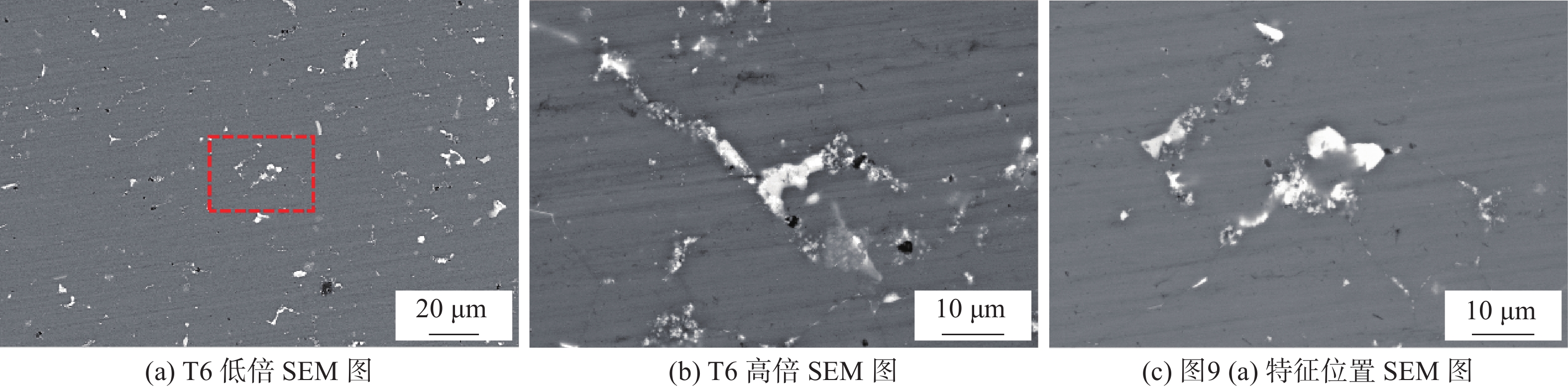
图 9 T6试样中部SEM形貌
Figure 9. SEM image of the middle part of T6 sample. (a) low magnification SEM image of T6 state sample; (b) high magnification SEM image of T6 state sample; (c) SEM image of the dashed rectangular zone in Fig.9(a)
![]()
图 11 T6试样析出相点扫描结果
Figure 11. Spot Scanning Results of precipitation along grain boundaries in T6 Sample. (a) SEM images of grain boundaries precipitates in T6 state sample; (b) EDS results of grain boundaries precipitates
![]()
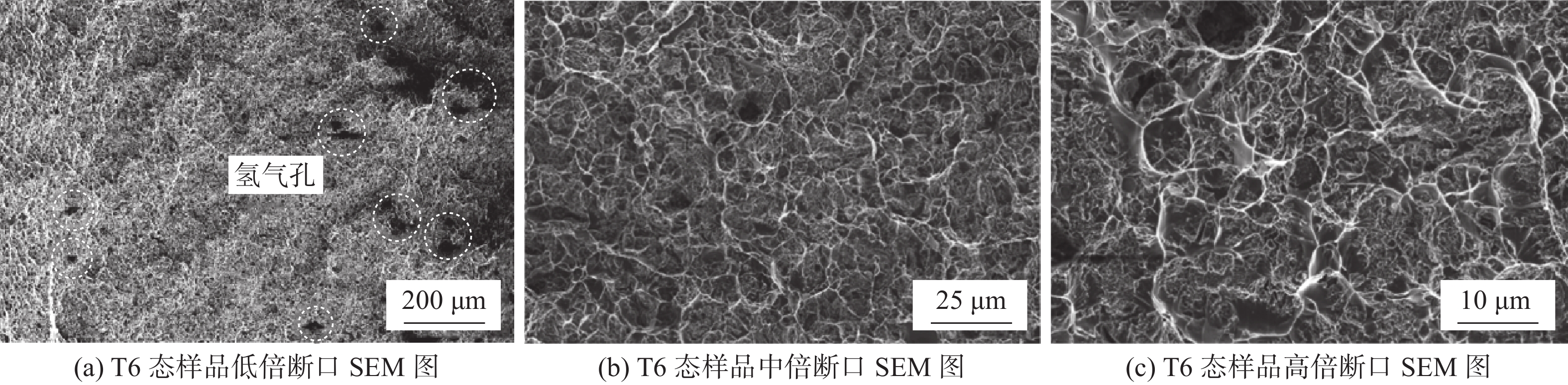
图 14 T6态拉伸断口SEM图
Figure 14. SEM image of T6 state tensile fracture surface. (a) fracture surface SEM images of T6 state sample at low magnification; (b) fracture surface SEM images of T6 state sample at medium magnification; (c) fracture surface SEM images of T6 state sample at high magnification
表 1 焊丝化学成分(质量分数,%)
Table 1 Chemical composition of welding wire
Zn Mg Ti Cu Al 8.6 3.2 1.8 1.8 余量  下载: 导出CSV
表 2 7075铝合金基板化学成分(质量分数,%)
Table 2 Chemical composition of 7075 aluminum alloy substrate
Si Fe Cu Mn Mg Cr Ti Zn Al 0.06 0.16 1.5 0.06 2.62 0.22 0.05 5.59 余量
下载: 导出CSV
表 3 不同焊接电流单道单层焊接试样宏观形貌和截面形貌
Table 3 Macromorphology and cross-sectional morphology of single pass single-layer welding specimens with different welding currents
电流I/A 宏观形貌 截面形貌 熔宽W/mm 余高H/mm 余高系数γ 150 

7.60 4.44 0.58 170 

9.98 3.52 0.35 190 

12.42 3.50 0.28 210 

12.7 3.74 0.29
下载: 导出CSV
表 4 不同焊接速度单道单层焊接试样宏观形貌和截面形貌
Table 4 Macromorphology and cross-sectional morphology of single pass single-layer welding specimens with different welding speeds
焊接速度v/(mm·min−1) 宏观形貌 截面形貌 熔宽W/mm 余高H/mm 余高系数γ 250 

11.26 4.54 0.40 350 

11.90 3.54 0.30 450 

9.72 3.10 0.31 550 

7.85 2.92 0.37
下载: 导出CSV
表 5 增材试样化学成分(质量分数,%)
Table 5 Chemical composition of additive samples
Zn Mg Ti Cu Al 5.22 1.91 1.26 1.98 余量
下载: 导出CSV
表 6 T6态拉伸结果
Table 6 Tensile strength of T6 state samples
方向 抗拉强度
Rm /MPa屈服强度
ReL /MPa断后伸长率
A(%)横向 469.7±5.1 366.3±1.4 6.4±0.4 纵向 454.3±18.8 364.7±16.7 5.9±0.5
下载: 导出CSV
-
[1] 张铭洋, 蒋熠鸣, 王春明, 等. 后热处理对激光焊接7075铝合金显微组织与力学性能影响[J]. 焊接学报, 2022, 43(8): 13 − 18. Zhang Mingyang, Jiang Yiming, Wang Chunming, et al. Effect of post-weld heat treatment on microstructure and mechanical properties of laser welded 7075Al alloy[J]. Transactions of the China Weiding Institution, 2022, 43(8): 13 − 18.
[2] Georgantzia E, Gkantou M, Kamaris G S, et al. Aluminium alloys as structural material: A review of research[J]. Engineering Structures, 2021, 227: 111372 doi: 10.1016/j.engstruct.2020.111372
[3] 林三宝, 夏云浩, 董博伦, 等. 双丝电弧增材制备Al-Mg-Zn-Cu-Sc铝合金工艺与组织性能[J]. 焊接学报, 2022, 43(11): 36 − 42. Lin Sanbao, Xia Yunhao, Dong Bolun, et al. Microstructure and properties of dual-wire arc additive manufacturing of Al-Mg-Zn-Cu-Sc alloy[J]. Transactions of the China Weiding Institution, 2022, 43(11): 36 − 42.
[4] Kanishka K, Acherjee B. Revolutionizing manufacturing: A comprehensive overview of additive manufacturing processes, materials, developments, and challenges[J]. Journal of Manufacturing Processes, 2023, 107: 574 − 619. doi: 10.1016/j.jmapro.2023.10.024
[5] Norrish J, Polden J, Richardson I, et al. A review of wire arc additive manufacturing: development, principles, process physics, implementation and current status[J]. Journal of Physics D: Applied Physics, 2021, 54(47): 473001. doi: 10.1088/1361-6463/ac1e4a
[6] Ramazani H, Kami A, Metal FDM, et al. A new extrusion-based additive manufacturing technology for manufacturing of metallic parts: a review[J]. Progress in Additive Manufacturing, 2022, 7(4): 609 − 626. doi: 10.1007/s40964-021-00250-x
[7] Langelandsvik G, Akselsen O M, Furu T, et al. Review of aluminum alloy development for wire arc additive manufacturing[J]. Materials, 2021, 14(18): 5370. doi: 10.3390/ma14185370
[8] Weman K. Welding processes handbook [M]. Cambridge: Woodhead Publishing Limited, 2011.
[9] Dong B, Cai X, Lin S, et al. Wire arc additive manufacturing of Al-Zn-Mg-Cu alloy: microstructures and mechanical properties[J]. Additive Manufacturing, 2020, 36: 101447. doi: 10.1016/j.addma.2020.101447
[10] Doumenc G, Couturier L, Courant B, et al. Investigation of microstructure, hardness and residual stresses of wire and arc additive manufactured 6061 aluminium alloy[J]. Materialia, 2022, 25: 101520. doi: 10.1016/j.mtla.2022.101520
[11] Hauser T, Reisch R T, Breese P P, et al. Porosity in wire arc additive manufacturing of aluminium alloys[J]. Additive manufacturing, 2021, 41: 101993. doi: 10.1016/j.addma.2021.101993
[12] Ryan E, Sabin T, Watts J, et al. The influence of build parameters and wire batch on porosity of wire and arc additive manufactured aluminium alloy 2319[J]. Journal of Materials Processing Technology, 2018, 262: 577 − 584. doi: 10.1016/j.jmatprotec.2018.07.030
[13] Morais P J, Gomes B, Santos P, et al. Characterisation of a high-performance Al–Zn–Mg–Cu alloy designed for wire arc additive manufacturing[J]. Materials, 2020, 13(7): 1610. doi: 10.3390/ma13071610
[14] Ma C, Chen L, Cao C, et al. Nanoparticle-induced unusual melting and solidification behaviours of metals[J]. Nature Communications, 2017, 8(1): 14178. doi: 10.1038/ncomms14178
[15] Martin J H, Yahata B D, Hundley J M, et al. 3D printing of high-strength aluminium alloys[J]. Nature, 2017, 549(7672): 365 − 369. doi: 10.1038/nature23894
[16] Yuan T, Ren X, Chen S, et al. Al–Zn–Mg–Cu alloy with both high strength and high plasticity fabricated with wire arc additive manufacturing[J]. Science and Technology of Welding and Joining, 2023, 28(1): 81 − 88. doi: 10.1080/13621718.2022.2117532
[17] Xiao F, Wang S, Wang Y, et al. Niobium nanoparticle-enabled grain refinement of a crack-free high strength Al-Zn-Mg-Cu alloy manufactured by selective laser melting[J]. Journal of Alloys and Compounds, 2022, 900: 163427. doi: 10.1016/j.jallcom.2021.163427
[18] Yuan L, Pan Z, Ding D, et al. Fabrication of metallic parts with overhanging structures using the robotic wire arc additive manufacturing[J]. Journal of Manufacturing Processes, 2021, 63: 24 − 34. doi: 10.1016/j.jmapro.2020.03.018
[19] Wu B, Pan Z, Ding D, et al. Effects of heat accumulation on microstructure and mechanical properties of Ti6Al4V alloy deposited by wire arc additive manufacturing[J]. Additive Manufacturing, 2018, 23: 151 − 160. doi: 10.1016/j.addma.2018.08.004
[20] Gupta R, Chaudhari G, Daniel B, et al. Strengthening mechanisms in ultrasonically processed aluminium matrix composite with in-situ Al3Ti by salt addition[J]. Composites Part B: Engineering, 2018, 140: 27 − 34. doi: 10.1016/j.compositesb.2017.12.005
[21] Zhao Kai, T Gao ong, Yang Huabing, et al. Enhanced grain refinement and mechanical properties of a high strength Al-Zn-Mg-Cu-Zr alloy induced by TiC nano-particles[J]. Materials Science and Engineering A, 2021(806): 140852.
[22] 李彩琼, 夏琳, 王明刚, 等. 固溶工艺对Al-Zn-Mg-Cu合金组织与性能的影响[J]. 材料热处理学报, 2023, 44(11): 52 − 61. Li Caiqiong, Xia Lin, Wang Minggang, et al. Effect of solution process on microstructure and properties of Al-Zn-Mg-Cu alloy[J]. Transactions of the China Weiding Institution, 2023, 44(11): 52 − 61.
[23] Chen S, Xu M, Yuan T, et al. Thermal–microstructural analysis of the mechanism of liquation cracks in wire-arc additive manufacturing of Al–Zn–Mg–Cu alloy[J]. Journal of Materials Research and Technology, 2022, 16: 1260 − 1271. doi: 10.1016/j.jmrt.2021.12.016
[24] Tillová E, PanuŠková M. Effect of solution treatment on intermetallic phases morphology in AlSi9Cu3 cast alloy[J]. Metalurgija, 2008, 47(3): 207 − 210.
[25] Ren X, Jiang X, Yuan T, et al. Microstructure and properties research of Al-Zn-Mg-Cu alloy with high strength and high elongation fabricated by wire arc additive manufacturing[J]. Journal of Materials Processing Technology, 2022, 307: 117665. doi: 10.1016/j.jmatprotec.2022.117665
[26] Gu J, Ding J, Williams S W, et al. The effect of inter-layer cold working and post-deposition heat treatment on porosity in additively manufactured aluminum alloys[J]. Journal of Materials Processing Technology, 2016, 230: 26 − 34. doi: 10.1016/j.jmatprotec.2015.11.006
-
期刊类型引用(0)
其他类型引用(2)


计量
- 文章访问数: 108
- HTML全文浏览量: 35
- PDF下载量: 39
- 被引次数: 2
