Research progress of low-temperature sintering nano silver paste
-
摘要: 金属纳米颗粒因尺寸效应可在较低温度下实现烧结,并表现出优异的电热学性能、机械可靠性和耐高温性能,成为适配第三代半导体的关键封装材料. 其中,银因具有高抗氧化性的优势被广泛研究,并成功应用于商业应用中. 基于功率器件封装领域,总结了低温烧结纳米银膏的研究现状,并从纳米银颗粒的烧结机制、制备方法、性能优化、烧结方法、可靠性及商业应用等方面展开说明. 结果表明,随着对烧结理论的进一步认识,可以有目的性地优化纳米银颗粒的尺寸和表面修饰,同时基于纳米银颗粒衍生出新型的产品,以适应不同的烧结工艺和性能要求.Abstract: Because of the size effect, metal nanoparticles have become the key packaging materials suitable for the third-generation semiconductor due to their low-temperature sintering, excellent electrothermal properties, mechanical reliability and high-temperature resistance. Silver has been widely studied and successfully applied in commercial applications because of its high oxidation resistance. Based on the field of power device packaging, the research progress of the low-temperature sintering nano silver paste was summarized, including the sintering mechanism, preparation method, performance optimization, sintering methods, reliability and commercial application of silver nanoparticles. The results showed that with the better understanding of sintering theory, the size and surface modification of silver nanoparticles can be purposefully optimized, and new products based on silver nanoparticles can be derived to adapt to different sintering processes and performance requirements.
-
Keywords:
- nano-Ag paste /
- low-temperature sintering /
- sintering process /
- reliability
-
0. 序言
2219铝合金属于可热处理强化的高强硬铝合金,凭借其优良的加工性能与耐腐蚀性能,广泛应用于运载火箭推进器贮箱结构等[1].常用于焊接2219铝合金的方法有电子束焊(electron beam welding,EBW)、激光焊(laser beam welding,LBW)、变极性钨极氩弧(variable polarity tungsten inert gas,VPTIG)焊等[2-6],但是以上熔焊的接头强度仅能达到母材的50%~70%,且焊接接头出现气孔与裂纹的倾向性极高[7].搅拌摩擦焊(friction stir welding,FSW)凭借其突出的冶金优势,非常适合于铝、镁等低熔点轻金属焊接,在航空、航天等领域铝合金的焊接中得到了大量应用[8-9].但是由于搅拌摩擦焊过程中不均匀的受热和冷却,以及较大的焊接力,焊接接头中存在较大的残余拉应力,将极大地影响接头的疲劳强度、耐腐蚀性能与装配精度,因此如何降低铝合金搅拌摩擦焊接头残余应力至关重要.
目前常用的降低残余应力的方法主要分为两类:一是时效法,包括自然时效(利用环境温度与时间效应使应力释放)与热处理时效(加热至退火温度再可控降温)[10-11];二是机械变形法,如锤击、振动、喷丸等[12-13].但热处理方法耗时较长,容易造成焊件氧化、变形等;振动法无法对应力腐蚀构件使用,其它方法如超声冲击、激光冲击等方法改善残余应力效果较好,但成本较高.
冷喷涂是将一定温度与压力的气体(氮气、氦气等)在特殊设计的Laval 喷嘴内加速至300 ~ 1200 m/s后,将粉末颗粒在低温高速的条件下以完全固态形式撞击基体产生塑性变形而形成涂层或沉积体的一种技术,现已应用于各类功能涂层制备、表面修复等领域[14].前期研究表明,采用高压高温气体将冷喷涂粉末颗粒沉积在基体上的过程中存在“热流冲击”以及“颗粒喷丸”两种效应,课题组前期研究分析了两种效应对降低2219铝合金VPTIG焊接头残余应力的影响[15-16],以及利用冷喷涂技术协同改善了3 mm厚2024铝合金FSW接头强塑性[17-18].
为了进一步扩大冷喷涂技术的应用范围,文中研究了冷喷涂技术对4 mm厚2219铝合金搅拌摩擦焊接头残余应力与力学性能的影响.
1. 试验方法
试验采用4 mm厚2219铝合金板材,其化学成分见表1[15]. 采用对接方式进行FSW. 焊接工艺参数:转速600 r/min,焊接速度200 mm/min.搅拌头尺寸:轴肩直径18 mm,搅拌针直径4.5 mm,搅拌针长度3.8 mm. 焊前,对接头待焊面用砂纸打磨,并用丙酮清洗;焊后,为了便于粘贴应变花,轻轻打磨两侧飞边.
表 1 2219铝合金的化学成分(质量分数,%)Table 1. Chemical compositions of 2219 aluminum alloySi Fe Cu Mn Mg Zn Ti V Zr Al 0.3 0.3 6.5 0.6 0.05 0.1 0.15 0.1 0.15 余量 文献[19]表明,搅拌摩擦焊接头残余应力以纵向应力为主, 横向应力相对很小. 故文中只研究了纵向残余应力,检测焊态残余应力后在焊缝及部分母材区域进行冷喷涂试验,然后再检测冷喷涂后2219铝合金FSW接头的残余应力.采用盲孔法进行残余应力检测,其原理是在待测表面应变花中心打小孔,由于残余应力的释放导致三维应变重新分布,测量其应变释放量,通过式(1)~式(7)便可计算出该点的残余应力值[20].
$$ \begin{aligned} {\sigma _1}{\rm{ = }}&\dfrac{E}{{4B}}\sqrt {{{\left( {\varepsilon _{{\text{0}^ \circ }}+ {\varepsilon _{{{90}^ \circ }}}} \right)}^2} + {{\left( {2{\varepsilon _{{{45}^ \circ }}} - {\varepsilon _{{\text{0}^ \circ }}} - {\varepsilon _{{{90}^ \circ }}}} \right)}^2}}+ \\ & \dfrac{{E\left( {{\varepsilon _{{\text{0}^ \circ }}} + {\varepsilon _{{{90}^ \circ }}}} \right)}}{{4A}} \end{aligned} $$ (1) $$ \begin{aligned} {\sigma _2}{\rm{ = }}&-\dfrac{E}{{4B}}\sqrt {{{\left( {{\varepsilon _{{\text{0}^ \circ }}} + {\varepsilon _{{{90}^ \circ }}}} \right)}^2} + {{\left( {2{\varepsilon _{{{45}^ \circ }}} - {\varepsilon _{{\text{0}^ \circ }}} - {\varepsilon _{{{90}^ \circ }}}} \right)}^2}}+ \\ & \dfrac{{E\left( {{\varepsilon _{{\text{0}^ \circ }}} + {\varepsilon _{{{90}^ \circ }}}} \right)}}{{4A}} \end{aligned} $$ (2) $$ \gamma {\rm{ = }}\dfrac{1}{2}\arctan \frac{{{\varepsilon _{{\text{0}^ \circ }}} - 2{\varepsilon _{{{45}^ \circ }}} + {\varepsilon _{{{90}^ \circ }}}}}{{{\varepsilon _{{\text{0}^ \circ }}} - {\varepsilon _{{{90}^ \circ }}}}} $$ (3) $$ A = - \frac{{1 + \mu }}{2}\frac{{{a^2}}}{{{r_1}{r_2}}} $$ (4) $$ B = - \frac{{2{R^2}}}{{{r_1}{r_2}}}\left[ {1 - \frac{{1 + \mu }}{4}\frac{{\left( {r_1^2 + {r_1}{r_2} + r_2^2} \right){a^2}}}{{{r_1}{r_2}}}} \right] $$ (5) $$ {\sigma _x} = \frac{{{\sigma _1} + {\sigma _2}}}{2} + \frac{{{\sigma _1} - {\sigma _2}}}{2}\cos 2\gamma $$ (6) $$ {\sigma _{{y}}} = \frac{{{\sigma _1} + {\sigma _2}}}{2} - \frac{{{\sigma _1} - {\sigma _2}}}{2}\cos 2\gamma $$ (7) 式中:σ1,σ2为主应力;A,B为释放系数;E为弹性模量;
${\varepsilon _{{{\text{0}}^ \circ }}}$ ,${\varepsilon _{{{45}^ \circ }}}$ ,${\varepsilon _{{{90}^ \circ }}}$ 分别为3个方向上应变花释放的应变;μ为泊松比;R为孔直径;a为孔半径;r1,r2为应变花两端到小孔的距离;γ为主应力σ1与X方向夹角;σx,σy为横向、纵向残余应力.图1为FSW接头冷喷涂过程的示意图. 冷喷涂粉末采用15~45 μm商用球形铜粉,平均粒径为28.9 μm,喷涂方向垂直于焊缝,工艺参数如表2所示. 冷喷涂路径及残余应力测量应变花摆放位置如图2所示.
表 2 冷喷涂工艺参数Table 2. Cold spraying process parameters温度
T/℃压力
P/MPa喷涂距离
d/mm喷涂速度v/(mm·s−1) 送粉速度ν0/(g·min−1) 500 3 30 50 80 沿垂直于焊缝的方向切割制作接头金相试样,用砂纸进行打磨,随后抛光,用Keller试剂(2.5 mL HNO3 + 1.5 mL HCl + 1 mL HF + 95 mL H2O)腐蚀. 在KEYENCE VHX-5000型光学显微镜下观察其组织形貌. 用LM248AT型维氏硬度计测量接头硬度分布情况,加载载荷1.96 N,加载时间10 s. 随后沿垂直于焊缝方向切割拉伸试样,采用Instron 3382型电子万能试验机进行拉伸试验,拉伸速率0.5 mm/min.
2. 结果与分析
2.1 冷喷涂前后2219铝合金FSW接头组织形貌
图3为2219铝合金FSW接头焊态及冷喷涂后的接头形貌. 从图3a可以看出,接头成形美观,未见孔洞及沟槽缺陷. 冷喷涂后涂层在宽度上覆盖了整个FSW接头区域(图3b).
图4为冷喷涂后的接头及涂层截面组织. 试验仅喷涂一遍,涂层厚度约为200 μm,如图4a所示,同时还可以看出FSW接头搅拌区保留了典型的搅拌摩擦焊的组织特征,搅拌区由细小的等轴再结晶组织构成.由图4b可以看出,基体与涂层界面处由于颗粒高速撞击发生了明显的塑性变形,金属表面产生强烈的塑性变形可能使晶粒细化,且具有较高的强度[21].
2.2 冷喷涂前后2219铝合金FSW接头残余应力
图5为冷喷涂前后接头表面残余应力分布情况. 从图5可以看出,2219铝合金焊态残余应力呈现“M”形,且均为拉应力,但非对称分布,由焊缝中心向母材方向残余应力先增大,峰值位于前进侧轴肩附近(热力影响区与热影响区边界),约为186 MPa,随后逐渐减小.其原因主要是搅拌摩擦焊过程中不均匀的热与机械搅拌作用造成的,前进侧金属受到较大的纵向拉伸应力且拉伸应力的方向与移动方向相同,在焊接过程中纵向拉伸应力持续累积并且与焊后冷却收缩作用叠加;而后退侧材料正好相反,在焊接过程中受到纵向压缩作用,残余应力略低,所以在焊缝两侧形成了不对称的残余应力场,在前进侧靠轴肩附近形成了残余应力峰值[19,22-23].
从图5还可以看出,冷喷涂态的接头残余应力较焊态接头,残余应力出现大幅度降低,分布更为均匀,且不存在较高的应力峰值(前进侧峰值残余应力由焊态的186 MPa降至43 MPa,降幅高达76.9%),轴肩外侧区域已经变为残余压应力.在冷喷涂过程中,低温高速状态下粉末颗粒持续撞击2219铝合金焊缝表面,从而使焊缝表面发生了较大的塑性变形,同时还有较高压力的热气体不断冲击,二者协同作用在焊缝表面产生压缩残余应力,可以抵消2219铝合金FSW接头原始的残余拉应力.前期研究表明,冷喷涂过程中的“热流冲击”效应相当于对基体起到了局部热处理的作用,可以使焊缝峰值残余应力有所降低,而“颗粒喷丸”效应产生的压应力则是冷喷涂降低残余拉应力的最主要因素[15,24].
2.3 力学性能
2.3.1 硬度分布
图6为焊态和冷喷涂态的接头横截面上表面与搅拌区厚度方向的硬度曲线.从图6可以看出,焊态接头的硬度分布与组织分布相关,硬度最低值出现在热力影响区,只有80 HV左右.母材显微硬度最高,沿热影响区、热力影响区方向逐渐降低,在两者界面处达到最低值,到搅拌区由于搅拌针的高速旋转与机械力作用,硬度又有一定的回升.
冷喷涂态接头硬度相比焊态显著增加,这是由于粉末颗粒在高速撞击接头表面时,发生较大的塑性变形,在接头表面产生了加工硬化的效果,从而使硬度提升. 前期研究表明,冷喷涂过程中的“热流冲击”效应会促使2024铝合金的铜、镁以及铜-镁原子团簇(guinier-preston-bagaryatsky,GPB)区及基体中的溶质原子团转变为S相(Al2CuMg),且此温度又不会使S相粗化. 此外,冷喷涂过程中的“颗粒喷丸”效应使得接头近表面区搅拌区晶粒细化.因此,冷喷涂过程既增加了沉淀强化相S相的数量,又细化了搅拌区的晶粒尺寸,双重作用促使喷涂态接头硬度高于焊态[17].此外,根据文献[25]所述,基体表面存在拉应力时,硬度将降低,而存在压应力时硬度将升高,前文所述冷喷涂过程使接头的残余拉应力大大降低,这也有助于硬度值的提高. 根据图6b中搅拌区厚度方向硬度分布所示,由于整个试验仅喷涂一遍,作用深度有限,约有1 mm左右,硬度值约增加25 ~ 30 HV.
2.3.2 拉伸性能
表3为冷喷涂前后2219铝合金FSW接头的拉伸性能. 从表3可以看出,冷喷涂后抗拉强度及断后伸长率均高于焊态下的接头.抗拉强度由316 MPa增加到336 MPa,提升6.3%,而断后伸长率增加更明显,提升85.7%.
表 3 冷喷涂前后接头的拉伸性能Table 3. Tensile properties before and after cold spraying状态 抗拉强度Rm/MPa 断后伸长率A(%) 焊态 316 3.5 冷喷涂态 336 6.5 图7为冷喷涂前后工程应力–应变曲线. 焊态与冷喷涂态的断裂位置照片如图8所示,可以看出经过冷喷涂处理后,断口发生了明显的颈缩现象,且在拉伸过程中涂层已经剥落.焊态与冷喷涂态接头均断裂在前进侧热力影响区和热影响区界面附近,且均呈45°角断裂.这与图6a的低硬度区域位置相吻合,符合高强铝合金FSW接头在低硬度区或弱结合面产生裂纹并扩展的弱区断裂规律[26].与此同时,在之前的残余应力测试过程中也表明前进侧热影响区和热力影响区界面处恰好位于纵向残余应力峰值位置,拉应力促进裂纹的扩展,因此较高的残余拉应力也会促使接头在此处断裂.
3. 结论
(1) 经过冷喷涂处理后2219铝合金FSW接头微观组织保留典型的搅拌摩擦焊的组织特征,但在基体与涂层界面处由于粉末颗粒的高速撞击发生了明显的塑性变形.
(2) 经过冷喷涂处理后2219铝合金FSW接头残余应力大幅度降低,峰值残余应力(前进侧轴肩附近)从186 MPa降至43 MPa,降幅高达76.9%,且整体应力分布变均匀,最大应力与最小应力差值减小.
(3) 经过冷喷涂处理的2219铝合金FSW接头上表面硬度整体增加25~30 HV,作用深度约为1 mm;2219铝合金FSW接头在冷喷涂处理后抗拉强度、断后伸长率均有所提高,其中抗拉强度提升6.3%,断后伸长率增幅高达85.7%.
-
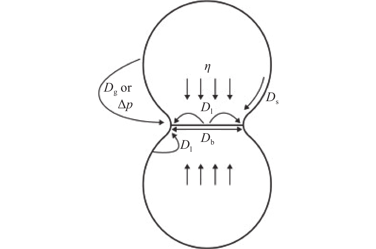
图 1 原子扩散通道类型模型[8]
Figure 1. Model of atom diffusion
图 2 不同烧结阶段的银烧结接头形貌[8]
Figure 2. Morphology of the Ag-sintered joints at different sintering stages
图 3 银纳米颗粒结构示意图[9]
Figure 3. Schematic diagram of silver nanoparticles structure
图 4 纳米银颗粒透射电子显微镜图[19]
Figure 4. Transmission electron microscope (TEM) image of Ag nanoparticles
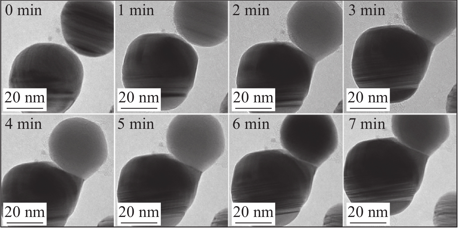
图 5 300 ℃下不同烧结时间纳米银颗粒的原位TEM图[20]
Figure 5. Situ TEM images of nanoparticles during different sintering times at 300 ℃
图 6 Ag纳米颗粒的烧结过程示意图[21]
Figure 6. Schematic diagrams of the sintering process of Ag nano-particles. (a) thick organic shells; (b) thin organic shells
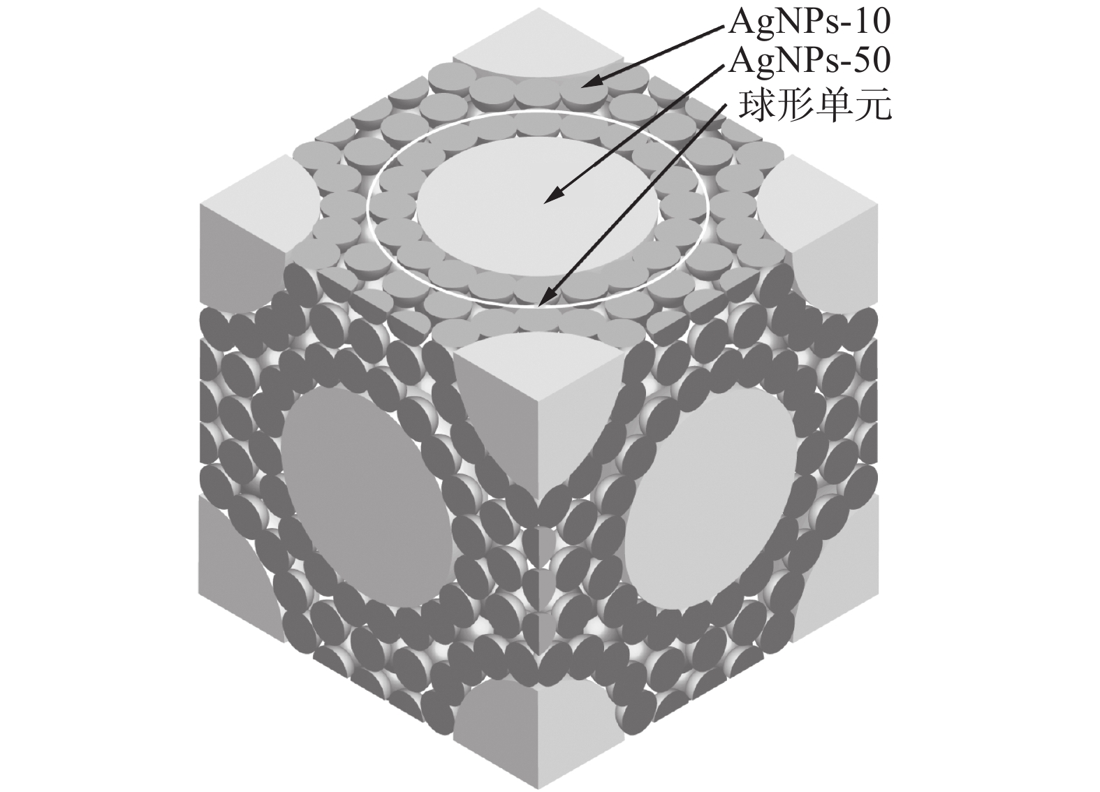
图 8 复合纳米银颗粒堆积示意图[22]
Figure 8. Stacking diagram of composite Ag nanoparticles
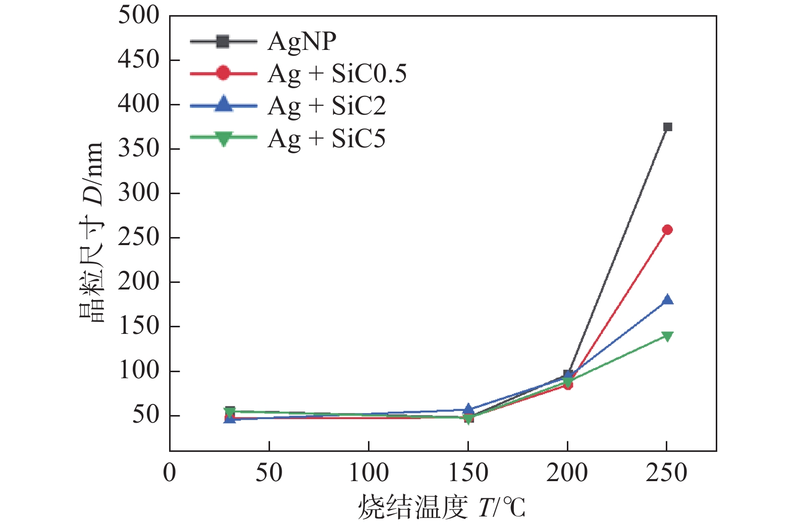
图 9 不同温度下不同组分浆料烧结组织的晶粒尺寸曲线[24]
Figure 9. Grain size curves of different pastes sintered at different temperature
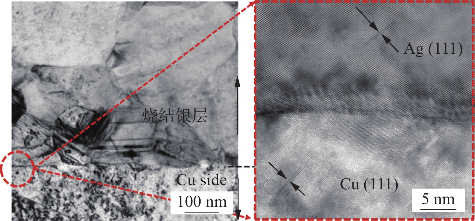
图 10 接头界面TEM图[9]
Figure 10. TEM image of the connector interface
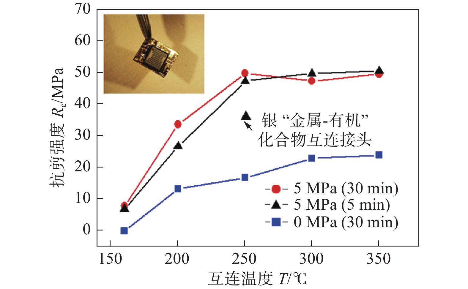
图 11 不同烧结条件下纳米银膏烧结互连结构的抗剪强度[25]
Figure 11. Shear strength of sintered AgNPs paste bonding joints with different sintering condition
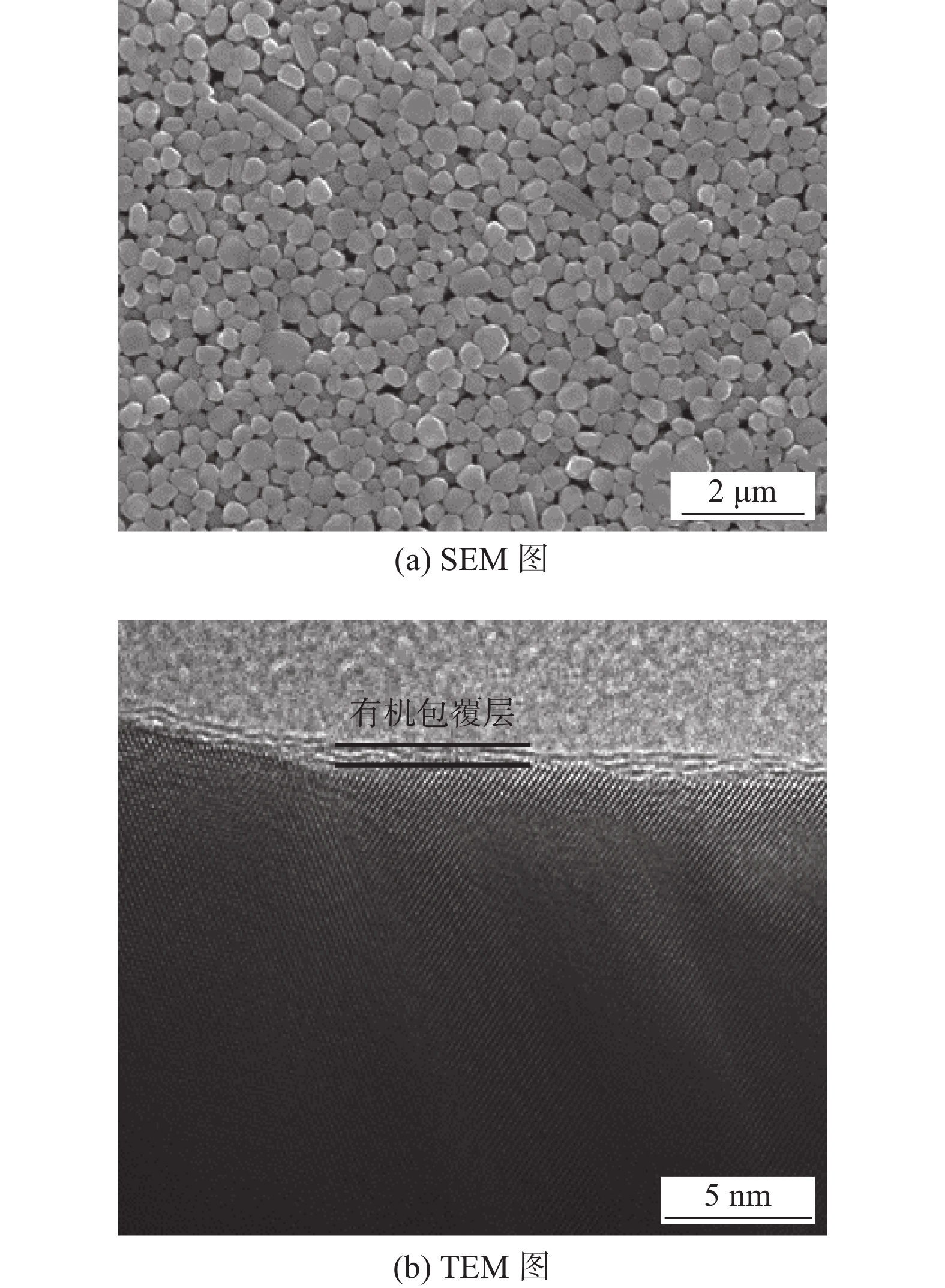
图 12 纳米银颗粒形貌[26]
Figure 12. Morphology of silver nanoparticles. (a) SEM image; (b) TEM image
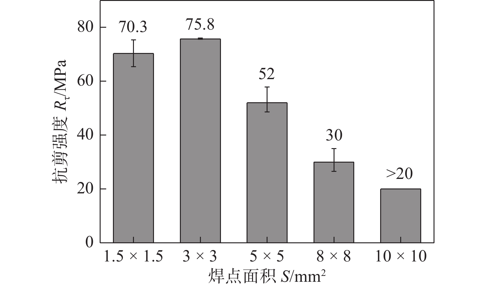
图 13 焊点面积对无压焊点抗剪强度的影响[26]
Figure 13. Shear strength of the pressureless joints with different areas
图 14 超声辅助互连工艺示意图[27]
Figure 14. Schematic diagram of ultrasonic-assisted interconnection process. (a) mounting chip; (b) introduction of ultrasonic assistance; (c) sintering
图 15 接头的剪切性能[27]
Figure 15. Shear performance of joints
图 16 电流辅助烧结[28]
Figure 16. Current assisted sintering. (a) schematic set-ups; (b) temperature profile of nano-Ag joints
图 17 不同测试温度下的抗剪强度[30]
Figure 17. Shear strengths under different testing temperatures
图 18 接头的抗剪强度与温度循环次数的关系[30]
Figure 18. Shear strength of joints versus number of temperature cycles
图 19 烧结银的粗化机制示意图[32]
Figure 19. Schematic diagram of coarsening behavior of sintered Ag. (a) microstructure of sintered-Ag; (b) structure of grain boundary; (c) formation of Ag2O; (d) decomposition of Ag2O; (e) grain coarsening
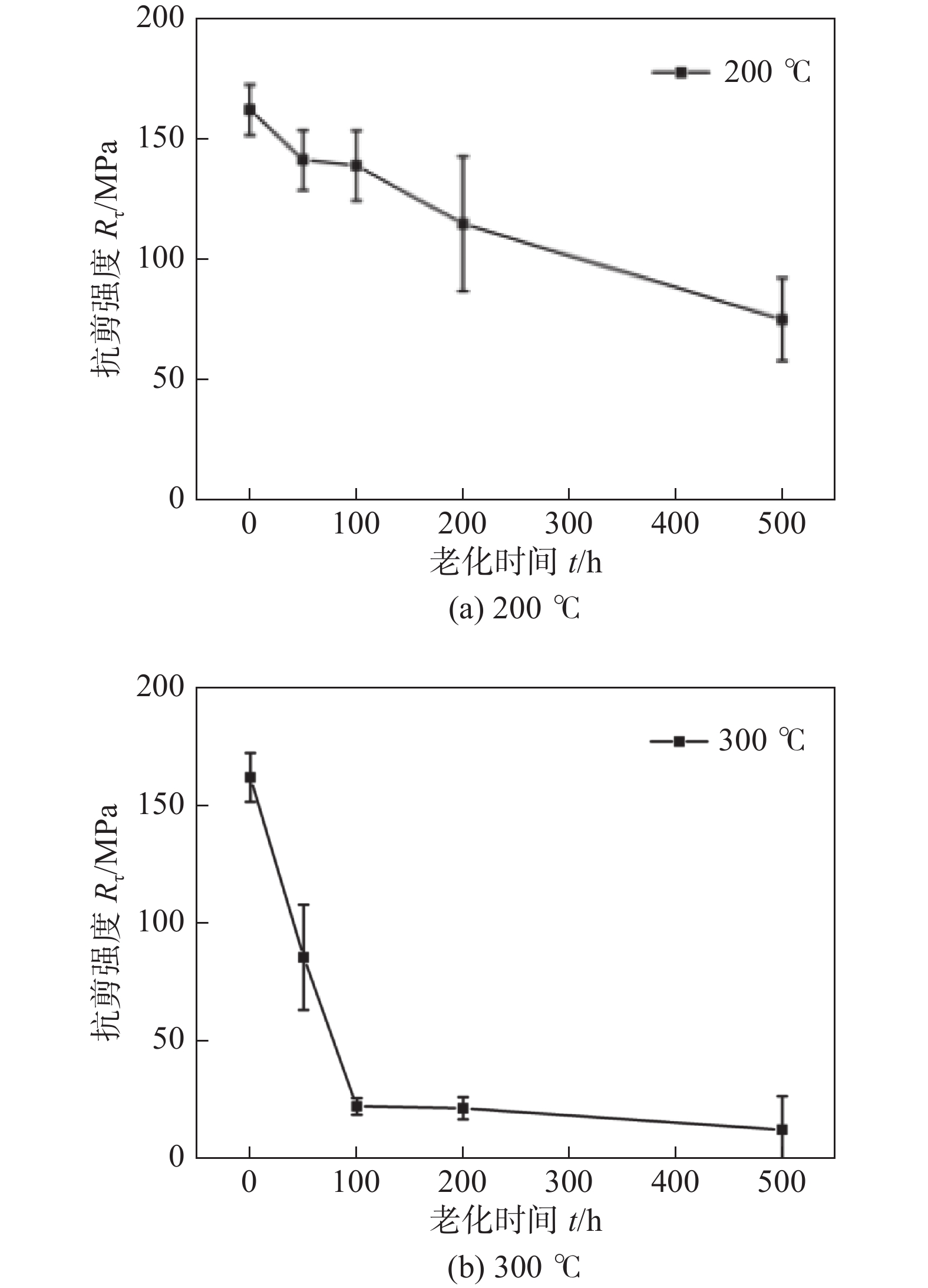
图 20 老化过程中抗剪强度与老化时间的关系[33]
Figure 20. Variation of shear strengths of sintered joints versus ageing time during ageing test. (a) 200 ℃; (b) 300 ℃
表 1 接头性能[28]
Table 1 Performance of nano-Ag joints
烧结方式 抗剪强度
Rτ /MPa孔隙率
rP(%)热阻
Rj /(K·W−1)电流辅助烧结 27 11.4 0.18 热压烧结 21 24.6 0.23 -
[1] Watson J, Castro G. High-temperature electronics pose design and reliability challenges[J]. Analog Dialogue, 2012, 46(2): 3 − 9.
[2] Chen Chuantong, Zhang Hao, Jiu Jingting, et al. Thermal fatigue behaviors of SiC power module by Ag sinter joining under harsh thermal shock test[J]. China Welding, 2022, 31(1): 15 − 21.
[3] Johnson R W, Evans J L, Jacobsen P. The changing automotive environment: high-temperature electronic[J]. IEEE Transactions on Electronics Packaging Manufacturing, 2004, 27(3): 164 − 176. doi: 10.1109/TEPM.2004.843109
[4] Yang J. A silicon carbide wireless temperature sensing system for high temperature applications[J]. Sensors, 2013, 13(2): 1884 − 1901. doi: 10.3390/s130201884
[5] Lea M C. Allotropic forms of silver[J]. American Journal of Science, 1889, 37(222): 476 − 491.
[6] Schwarzbauer H, Kuhnert R. Novel large area joining technique for improved power device performance[J]. IEEE Transactions on Industry Applications, 1991, 27(1): 93 − 95. doi: 10.1109/28.67536
[7] Vitos L, Ruban A V, Skriver H L, et al. The surface energy of metals[J]. Surface Science, 1998, 411(1-2): 186 − 202.
[8] Manikam V R. Die-attach materials for high temperature applications in microelectronics packaging[M]. Switzerland: Springer, 2019.
[9] Ide E, Angata S, Hirose A, et al. Metal–metal bonding process using Ag metallo-organic nanoparticles[J]. Acta Materialia, 2005, 53(8): 2385 − 2393. doi: 10.1016/j.actamat.2005.01.047
[10] Alarifi H, Hu A M, Yavuz M, et al. Silver nanoparticle paste for low-temperature bonding of copper[J]. Journal of Electronic Materials, 2011, 40(6): 1394 − 1402. doi: 10.1007/s11664-011-1594-0
[11] Wang S, Ji H J, Li M Y, et al. Fabrication of interconnects using pressureless low temperature sintered Ag nanoparticles[J]. Materials Letters, 2012, 85: 61 − 63. doi: 10.1016/j.matlet.2012.06.089
[12] Hu A, Guo J Y, Alarifi H, et al. Low temperature sintering of Ag nanoparticles for flexible electronics packaging[J]. Applied Physics Letters, 2010, 97(15): 153117. doi: 10.1063/1.3502604
[13] Tobita M, Yasuda Y, Ide E, et al. Optimal design of coating material for nanoparticles and its application for low-temperature interconnection[J]. Journal of Nanoparticle Research, 2010, 12(6): 2135 − 2144. doi: 10.1007/s11051-009-9775-y
[14] Jiang D, Xie J, Chen M, et al. Facile route to silver submicron-sized particles and their catalytic activity towards 4-nitrophenol reduction[J]. Journal of Alloys and Compounds, 2011, 509(5): 1975 − 1979. doi: 10.1016/j.jallcom.2010.10.107
[15] Park K, Seo D, Lee J. Conductivity of silver paste prepared from nanoparticles[J]. Colloids and Surfaces A:Physicochemical and Engineering Aspects, 2008, 313: 351 − 354.
[16] Liu J, Li X, Zeng X. Silver nanoparticles prepared by chemical reduction-protection method, and their application in electrically conductive silver nanopaste[J]. Journal of Alloys and Compounds, 2010, 494(1): 84 − 87.
[17] Bell N B, Antonio C B, Dimos D B. Development of conductivity in low conversion temperature silver pastes via addition of nanoparticles[J]. Journal of Materials Research, 2002, 17(9): 2423 − 2432. doi: 10.1557/JMR.2002.0354
[18] Wang X, Lin Y, Gu F, et al. A facile route to well-dispersed single-crystal silver nanoparticles from AgSO3 in water[J]. Journal of Alloys and Compounds, 2011, 509(27): 7515 − 7518. doi: 10.1016/j.jallcom.2011.04.106
[19] Nagasawa H, Maruyama M, Komatsu T, et al. Physical characteristics of stabilized silver nanoparticles formed using a new thermal-decomposition method[J]. Physica Status Solidi A-Applied Research, 2002, 191(1): 67 − 76. doi: 10.1002/1521-396X(200205)191:1<67::AID-PSSA67>3.0.CO;2-M
[20] Asoro M A, Kovar D, Ferreira P J. Effect of surface carbon coating on sintering of silver nanoparticles: in situ TEM observations[J]. Chemical Communications, 2014, 50(37): 4835. doi: 10.1039/C4CC01547A
[21] Wang S, Li M Y, Ji H J, et al. Rapid pressureless low-temperature sintering of Ag nanoparticles for high-power density electronic packaging[J]. Scripta Materialia, 2013, 69(11-12): 789 − 792.
[22] Li M Y, Xiao Y, Zhang Z H, et al. Bimodal sintered silver nanoparticle paste with ultrahigh thermal conductivity and shear strength for high temperature thermal interface material applications[J]. ACS Applied Materials and Interfaces, 2015, 7(17): 9157 − 9168. doi: 10.1021/acsami.5b01341
[23] Lee P C, Meisel D. Adsorption and surface-enhanced raman of dyes on silver and gold sols[J]. The Journal of Physical Chemistry, 1982, 86(17): 3391 − 3395. doi: 10.1021/j100214a025
[24] Hu B, Yang F, Peng Y, et al. Effect of SiC reinforcement on the reliability of Ag nanoparticle paste for high-temperature applications[J]. Journal of Materials Science: Materials in Electronics, 2019, 30(3): 2413 − 2418. doi: 10.1007/s10854-018-0514-y
[25] Yan J, Zou G, Wu A P, et al. Pressureless bonding process using Ag nanoparticle paste for flexible electronics packaging[J]. Scripta Materialia, 2012, 66(8): 582 − 585. doi: 10.1016/j.scriptamat.2012.01.007
[26] 吴炜祯, 杨帆, 胡博, 等. 用于大面积芯片互连的纳米银膏无压烧结行为[J]. 焊接学报, 2021, 42(1): 83 − 90. doi: 10.12073/j.hjxb.20201016002 Wu Weizhen, Yang Fan, Hu Bo, et al. Pressureless sintering behavior of nano-silver paste for large area chip interconnection[J]. Transactions of the China Welding Institution, 2021, 42(1): 83 − 90. doi: 10.12073/j.hjxb.20201016002
[27] Li Y, Jing H, Han Y, et al. Microstructure and joint properties of nano-silver paste by ultrasonic-assisted pressureless sintering[J]. Journal of Electronic Materials, 2016, 45(6): 3003 − 3012. doi: 10.1007/s11664-016-4394-8
[28] Xie Y J, Wang Y J, Mei Y H, et al. Rapid sintering of nano-Ag paste at low current to bond large area (> 100 mm2) power chips for electronics packaging[J]. Journal of Material Processing and Technology, 2018, 255(8): 644 − 649.
[29] Bai J G, Zhiye Z Z, Calata J N, et al. Low-temperature sintered nanoscale silver as a novel semiconductor device-metallized substrate interconnect material[J]. IEEE Transactions on Components and Packaging Technologies, 2006, 29(3): 589 − 593. doi: 10.1109/TCAPT.2005.853167
[30] Zheng H, Ngo K D, Lu G Q. Temperature cycling reliability assessment of die attachment on bare copper by pressureless nanosilver sintering[J]. IEEE Transactions on Device and Materials Reliability, 2015, 15(2): 214 − 219. doi: 10.1109/TDMR.2015.2417114
[31] Li Jiang. Thermo-mechanical reliability of sintered-silver joint versus lead-free solder for attaching large-area devices[D]. Virginia Polytechnic Institute and State University, Blacksburg, Virginia, 2010.
[32] Chen C, Choe C, Kim D, et al. Effect of oxygen on microstructural coarsening behaviors and mechanical properties of Ag sinter paste during high-temperature storage from macro to micro[J]. Journal of Alloys and Compounds, 2020, 834: 155173. doi: 10.1016/j.jallcom.2020.155173
[33] 杨帆. 低温烧结纳米银焊点互连行为及可靠性研究. [D]. 哈尔滨: 哈尔滨工业大学, 2021. Yang Fan. Study on interconnection behavior and reliability of low temperature sintering nano-silver joints[D]. Harbin: Harbin Institute of Technology, 2021.
[34] Paknejad S A, Dumas G, West G, et al. Microstructure evolution during 300 °C storage of sintered Ag nanoparticles on Ag and Au substrates[J]. Journal of Alloys and Compounds, 2014, 617: 994 − 1001. doi: 10.1016/j.jallcom.2014.08.062
[35] Chen C, Suganuma K, Iwashige T, et al. High-temperature reliability of sintered microporous Ag on electroplated Ag, Au, and sputtered Ag metallization substrates[J]. Journal of Materials Science: Materials in Electronics, 2017, 29(3): 1785 − 1797.
[36] Chua S T, Siow K S. Microstructural studies and bonding strength of pressureless sintered nano-silver joints on silver, direct bond copper (DBC) and copper substrates aged at 300 ℃[J]. Journal of Alloys and Compounds, 2016, 687: 486 − 498. doi: 10.1016/j.jallcom.2016.06.132


 下载:
下载:


