
Design of reflow oven furnace temperature based on quantum multi-objective optimization algorithm
-
摘要: 电路板焊接中心点的温度走势间接地反映了焊接质量,炉温曲线的优化设计对提高电路板焊接质量有着举足轻重的作用.文中运用傅里叶定律和集总参数法,建立反映电路板焊接中心温度变化的非稳态导热模型,并在满足制程界限和工艺要求的约束条件下,以传送带过炉速度最优和加热因子最小为目标,采用量子多目标粒子群算法(quantum multi-objective particle swarm optimization,QMOPSO)进行优化求解,获得了各温区的最优温度和电路板的最大过炉速度,并得到了最优炉温曲线.结果表明,优化后的电路板过炉速度为95.55 cm/min,接近速度上限,加热因子最小值为1753.04,炉温曲线整体呈现先上升后下降的趋势,峰值温度为240.01 ℃,接近温度制程界限下限,该结果为电路板等电子器件焊接工艺的实际工程应用和提高焊接质量提供参考.Abstract: The temperature trend of the welding center of circuit board indirectly reflects the welding quality. The optimization design of furnace temperature curve plays an important role in improving the welding quality of circuit board. In this paper, Fourier law and lumped parameter method were used to establish the unsteady heat conduction model reflecting the temperature change of the welding center of the circuit board. Under the constraints of meeting the process limits and technological requirements, the quantum multi-objective particle swarm optimization algorithm was used to optimize the solution with the goals of the optimal conveyor belt passing furnace speed and the minimum heating factor. The optimum temperature of each temperature region, the maximum passing speed of circuit board and the optimum temperature curve were obtained. The results show that the optimized circuit board passing through the furnace speed is 95.55 cm/min, which is close to the upper limit of the speed limit, and the minimum heating factor is 1 753.04. The furnace temperature curve shows a trend of rising first and then decreasing. The peak temperature is 240.01 ℃, which is close to the lower limit of the temperature process. The results provide strong guidance for practical engineering application and improvement of welding quality of electronic devices such as circuit boards.
-
0. 序言
对于电子束自熔焊而言,焊缝的熔深是指焊缝横截面上母材熔化的深度,而焊接接头的承载能力主要是由其有效连接区域决定,即接头的有效熔深. 有效熔深不足的大小会导致产品在服役过程中焊缝上的载荷超出其承载能力,发生开裂,对于薄壁小管径插接焊结构更是如此. 在电子束焊接过程中,聚焦电流、焊接速度、束流、倾斜角度等因素直接影响焊接质量,尤其对焊缝内部质量和力学性能的影响最为显著. 然而,焊缝内部质量和力学性能受电子束焊接工艺参数的影响并不是相互独立的,而是同时受制于多个工艺参数. 明晰各工艺参数对焊缝内部质量和力学性能的影响规律对相关试验和生产具有十分重要的意义.
响应面法是试验设计的重要方法,十分适合于解决参数优化类问题. 目前,响应面法在焊接领域具有广泛的应用. 丁亚茹等人[1]利用响应面法来研究7075铝合金激光焊的焊缝成形系数和焊缝截面积;Mohammadpour等人[2]基于响应面法对6022铝合金和镀锌钢的双焦点激光熔钎焊过程进行了优化;Kumar等人[3]引入响应面法建立了光纤激光焊接参数(激光功率、焊接速度、离焦量)与相应值(熔宽、热影响区宽度、熔合区面积)之间的回归模型;王洪潇等人[4]以焊缝成形质量和接头剪切拉伸载荷作为优化指标,采用响应面法建立了不锈钢车体激光工艺参数与预测响应值之间的数学模型,并优选焊接工艺参数. 薄壁小管径插接焊结构的有效熔深和接头抗剪承载力与焊接工艺参数有着密切的关系,最佳的参数组合能够获取焊缝截面形貌良好、力学性能优良的焊接接头.通过试验方法获取最佳焊接工艺参数,在时间、经济效益等方面均不可取.
通过响应面法中的Box-Behnken Design (BBD)[5-6]建立电子束焊接工艺参数与有效熔深和接头抗剪承载力之间的回归模型,研究工艺参数对有效熔深和接头抗剪承载力的影响规律,初步实现预测接头质量的目的. 通过优化相应质量指标(有效熔深、接头抗剪承载力)优化工艺参数,从而对电子束焊接HR-2抗氢钢插接焊的生产工艺进行指导.
1. 试验方法
试验采用HR-2抗氢不锈钢,其化学成分如表1所示. HR-2抗氢不锈钢除了具有稳定性和抗腐蚀性外,还具有比其它奥氏体钢高的屈服强度和良好的抗氢脆性能,广泛应用于航空、航天、核电、石油化工和石油天然气等行业.
表 1 HR-2抗氢钢的化学成分(质量分数,%)Table 1. Chemical compositions of HR-2 hydrogen resistant steelC Si Mn P S Ni Cr Fe ≤0.040 ≤1.00 8.00 ~ 10.00 ≤0.025 ≤0.015 5.50 ~ 8.00 19.00 ~ 21.50 余量 试验使用某中压电子束焊机进行焊接,试件分为A,B两组,每组件数相同且标记自然顺序号,并对A,B两组相同编号的试件采用相同的焊接工艺参数,A组用来测量焊缝有效熔深,B组用来测量接头抗剪承载力. A组试件采用线切割将其截断,保留焊缝部位,截断后采用慢走丝技术将零件按截面十字切割4份,其中一份保证完整的1/4,并留有一定磨量. 焊缝截面经过打磨、抛光、草酸腐蚀,采用超景深三维显微系统观察焊缝形貌,如图1所示,测量焊缝有效熔深(图2). B组试件采用GNT100型万能试验机测量其接头抗剪承载力.
![]() 图 1 HR-2抗氢钢电子束焊接部分接头形貌Figure 1. Morphology of the electron beam welded joints of some HR-2 hydrogen resistant steel. (a) specimen 7; (b) specimen 21; (c) specimen 22; (d) specimen 25; (e) specimen 6 ; (f) specimen 14; (g) specimen 26; (h) specimen 29
图 1 HR-2抗氢钢电子束焊接部分接头形貌Figure 1. Morphology of the electron beam welded joints of some HR-2 hydrogen resistant steel. (a) specimen 7; (b) specimen 21; (c) specimen 22; (d) specimen 25; (e) specimen 6 ; (f) specimen 14; (g) specimen 26; (h) specimen 29![]() 图 2 电子束插接焊接头结构示意图(mm)Figure 2. Schematic diagram of the electron beam butt welding joint structure
图 2 电子束插接焊接头结构示意图(mm)Figure 2. Schematic diagram of the electron beam butt welding joint structure2. 数据处理方法
2.1 因素水平设计
针对某种具体产品电子束焊接生产过程中加速电压、工作距离通常保持不变,因此选取聚焦电流、焊接速度、束流和倾斜角度4个参数作为变量因素,以有效熔深和接头抗剪承载力为响应值,在焊接过程中其它参数如加速电压、束振荡等保持恒定. 焊接工艺参数的取值范围决定了所建模型的合理性、实用性和预测结果的置信度. 为保证焊缝表面无裂纹、咬边、焊瘤、气孔等焊缝成形质量缺陷及焊缝有效深度内无裂纹、未熔合、夹渣、气孔密集区(按照GB/T 22085.1—2008《电子束及激光焊接接头缺欠质量分级指南 第1部分:钢》中的B级)等缺陷,首先进行了前述4个参数的单因素焊接工艺试验,通过金相横截面分析确定了聚焦电流、焊接速度、束流和倾斜角度4个参数的取值范围,制定了4因素3水平的BBD试验方案完成HR-2抗氢不锈钢的电子束焊,其真实值与编码值如表2所示. 试验方案及响应值如表3所示.
表 2 工艺参数水平编码及真实值表Table 2. Process parameter level coding and true value table水平 聚焦电流
If /A焊接速度
v/(mm·s−1)束流
Ib /mA倾斜角度
θ/(°)1 2.49 11.40 8.65 15 0 2.46 10.00 8.20 11 −1 2.43 8.60 7.75 7 表 3 试验方案及相对应的响应值Table 3. Test scheme and corresponding response value试验序号 聚焦电流If /A 焊接速度v/(mm∙s−1) 束流Ib/mA 倾斜角度θ/(°) 有效熔深d/μm 抗剪承载力F/kN 1 2.49 10.00 8.20 15 360.07 3.856 2 2.43 10.00 8.65 11 1 997.30 16 137 3 2.46 10.00 8.20 11 1 397.18 13.037 4 2.43 10.00 7.75 11 2 117.32 16.352 5 2.43 10.00 8.20 7 2 252.73 16.779 6 2.46 10.00 8.65 15 830.92 8.938 7 2.46 10.00 8.20 11 1 275.58 12.330 8 2.46 11.40 8.20 7 1 840.34 15.907 9 2.46 10.00 7.75 7 1 717.24 16. 096 10 2.46 10.00 8.20 11 1 357.18 13.725 11 2.46 8.60 8.65 11 1 175.61 13.681 12 2.46 11.40 8.20 15 815.54 8.120 13 2.46 10.00 8.65 7 1 975.75 15.935 14 2.49 10.00 8.65 11 787.84 8.388 15 2.49 10.00 7.75 11 575.49 6.710 16 2.49 8.60 8.20 11 775.53 7.844 17 2.43 10.00 8.20 15 1 369.49 13.696 18 2.46 10.00 8.20 11 1 375.64 13.265 19 2.43 11.40 8.20 11 1 796.56 14.908 20 2.46 10.00 8.20 11 1 320.56 13.018 21 2.46 8.60 7.75 11 1 427.96 14.690 22 2.43 8.60 8.20 11 2 203.49 16.368 23 2.49 11.40 8.20 11 827.85 7.564 24 2.46 8.60 8.20 7 2 172.71 16.383 25 2.46 8.60 8.20 15 787.84 8.046 26 2.46 10.00 7.75 15 744.76 7.013 27 2.46 11.40 8.65 11 1 461.81 12.204 28 2.49 10.00 8.20 7 1 089.44 11.404 29 2.46 11.40 7.75 11 1 311.02 11.557 2.2 建立回归模型
以有效熔深和接头抗剪承载力作为响应指标,通过Design-Expert软件对聚焦电流、焊接速度、束流和倾斜角度4个自变量,以及有效熔深和接头抗剪承载力因变量进行二阶模型拟合,实现自变量的优化和响应指标的预测[7-8]. 若有k个独立变量,所有独立变量均连续可测、可调,则响应函数为
$$ Y=\stackrel{·}{{\beta }_{0}} + {\displaystyle \sum _{i=1}^{k}{\stackrel{·}{\beta }}_{i}{x}_{i}} + {\displaystyle \sum _{i=1}^{k}{\stackrel{·}{\beta }}_{ii}{x}_{i}^{2}} + {\displaystyle \sum _{i=1}^{k}{\displaystyle \sum _{j=1}^{k}{\stackrel{·}{\beta }}_{ij}{x}_{i}{y}_{j}}} + \varepsilon $$ (1) 式中:Y为预测响应值;xi为自变量;
$ \stackrel{·}{{\beta }_{0}} $ ,$ \stackrel{·}{{\beta }_{i}} $ ,$ \stackrel{·}{{\beta }_{ii}} $ ,$ \stackrel{·}{{\beta }_{ij}} $ 为回归系数;$ \varepsilon $ 为噪音或误差项.3. 结果与分析
3.1 多元非线性回归模型
有效熔深采用立方模型,其模型的方差分析结果如表4所示. 模型F值为60.48,表明模型显著,F值只有0.01%的可能性会因为噪声而变大,模型Prob > F值小于0.01%,意味着该模型显著,R2 =99.55% (R2越接近1,越显著). 对失拟项检验来说,如果失拟项Prob > F值大于0.05,说明所得模型与实际拟合中非正常误差所占比例小,即失拟项不显著,回归模型拟合较好. 从表4可以看出,模型失拟项的Prob > F值为0.0650高于0.05,说明模型失拟不显著,能正确反映有效熔深由聚焦电流、焊接速度、束流和倾斜角度之间的关系,回归模型可以较好地对结果进行预测. 由表4可知,聚焦电流、倾斜角度对有效熔深的影响最为显著. 最终的数学模型为
表 4 有效熔深模型方差分析Table 4. ANOVA for effective weld penetration reduced cubic model项目 平方和SS/105 自由度f 均放值MS /105 F值 Prob>F值 模型 80.22 22 3.646 60.48 < 0.000 1 If 11.80 1 11.80 195.74 < 0.000 1 θ 11.21 1 11.21 185.88 < 0.000 1 vIf 0.527 276 4 1 0.527 276 4 8.75 0.025 4 vIb 0.406 304 6 1 0.406 304 6 6.74 0.040 9 IfIb2 0.418 443 5 1 0.418 443 5 6.94 0.038 8 残差 0.361 760 2 6 0.060 293 4 失拟项 0.269 499 2 2 0.134 749 6 5.84 0.065 0 绝对误差 0.092 261 0 4 0.023 065 3 总离差 80.58 28 $$ \begin{split} & d = 345.23 - 543.18{I_{\rm{f}}} - 529.33\theta + 114.81v{I_{\rm{f}}} + \\&\qquad 91.83v{I_{\rm{b}}} - 120.07{I_{\rm{f}}}I_{\rm{b}}^2 \end{split} $$ (2) F采用平方模型,方差分析如表5所示,F值检验、R2检验、失拟项检验均表明模型显著. 聚焦电流If、焊接速度v和倾斜角度θ对有效熔深的影响最为显著。最终的数学模型为
表 5 接头抗剪承载力模型方差分析Table 5. ANOVA for the shear capacity of welded joins reduced quadratic model项目 平方和SS /107 自由度f 均方值MS /106 F值 Prob > F值 模型 37.13 14 26.52 36.23 < 0.000 1 If 19.58 1 195.8 267.50 < 0.000 1 v 0.379 9 1 3.799 5.19 0.038 9 θ 15.29 1 152.9 208.88 < 0.000 1 θIf 0.498 4 1 4.984 6.81 0.020 6 If2 0.729 9 1 7.299 9.97 0.007 0 θ2 0.404 7 1 4.047 5.53 0.033 9 残差 1.025 14 0.732 0 失拟项 0.923 0 10 0.923 0 3.63 0.113 0 绝对误差 0.101 8 4 0.254 6 总离差 38.15 28 $$\begin{split} & Y = 13\;075.00 - 4\;039.50{I_{\rm{f}}} - 562.67v - 3\;569.58\theta - \\& \qquad 1\;116.25\theta {I_{\rm{f}}} - 1\;060.75I_{\rm{f}}^2 - 789.88{\theta ^2} \end{split} $$ (3) 3.2 响应面法分析
3.2.1 有效熔深的响应面法分析
图3为各工艺参数对有效熔深的影响. 从图3可以看出,聚焦电流和倾斜角度对有效熔深的影响最为显著,并且两者对有效熔深的影响程度和方向基本一致;其次是焊接速度,有效熔深随聚焦电流或倾斜角度的增大而迅速减小,随焊接速度的增大而缓慢减小,随束流的增大而缓慢增大. 增大聚焦电流或者倾斜角度,均会使有效熔深迅速减小,原因是增加聚焦电流使磁聚焦作用增强,电子束流焦点上移(图4),到达工件表面的束流截面积增大,能量密度减小,穿透能力减弱,有效熔深减小,而增大倾斜角度将导致接头轴线与连接面之间角度增大,从而削弱有效熔深.
![]() 图 4 聚焦电流与电子束焦点位置关系示意图Figure 4. Schematic diagram of the relationship between focusing current and electron beam focal position
图 4 聚焦电流与电子束焦点位置关系示意图Figure 4. Schematic diagram of the relationship between focusing current and electron beam focal position图5为有效熔深的响应面曲图和等值线图. 图5a和图5d为束流8.2 mA,倾斜角度11º时,聚焦电流和焊接速度对有效熔深的交互影响. 当聚焦电流小于2.46 A、有效熔深大于1 500 μm,聚焦电流大于2.48 A时,随着焊接速度由8.60 mm/s增加到11.40 mm/s,有效熔深变化幅度不大. 图5b和图5e为焊接速度10.00 mm/s、倾斜角度11º时,束流和聚焦电流对有效熔深的交互影响. 当束流在7.75 ~ 8.65 mA时,减小聚焦电流有助于增大有效熔深.图5c和图5f为束流8.20 mA,焊接速度10.00 mm/s时,聚焦电流和倾斜角度对有效熔深的交互作用. 由等值线图可以看出,不同的参数组合可以取得相同的有效熔深,且可以根据等值线区域优化参数组合. 当聚焦电流为2.46 A、倾斜角度由7º增加到15º时,有效熔深由2000 μm减小至500 μm.
![]() 图 5 有效熔深的响应面曲图和等值线图Figure 5. Response surface 3D graph and contour graph of effective penetration. (a) d = f ( If, v) response surface 3D graph; (b) d = f (If, Ib) response surface 3D graph; (c) d = f ( If, θ ) response surface 3D graph; (d) d = f ( If, v ) contour graph; (e) d = f ( If, Ib) contour graph; (f) d = f ( If, θ ) contour graph
图 5 有效熔深的响应面曲图和等值线图Figure 5. Response surface 3D graph and contour graph of effective penetration. (a) d = f ( If, v) response surface 3D graph; (b) d = f (If, Ib) response surface 3D graph; (c) d = f ( If, θ ) response surface 3D graph; (d) d = f ( If, v ) contour graph; (e) d = f ( If, Ib) contour graph; (f) d = f ( If, θ ) contour graph3.2.2 接头抗剪承载力的响应面法分析
图6为各工艺参数对接头抗剪承载力的影响,可以看出,聚焦电流和倾斜角度对接头抗剪承载力具有显著影响,而焊接速度和束流对接头抗剪承载力影响不显著. 接头抗剪承载力随着聚焦电流或倾斜角度的增大而减小. 显然,小的聚焦电流或倾斜角度可使有效熔深增加,从而提高接头抗剪承载力;但小的聚焦电流会导致电子束焊缝窄而深,形成“钉尖”缺陷,小的倾斜角度可能会烧蚀零件. 而另一方面,选用大聚焦电流、大倾斜角度,由于作用在工件表面上的电子束能量密度低、接头轴线与连接面之间角度增大而使有效熔深减小,从而降低接头抗剪承载力. 因此无论是小聚焦电流小倾斜角度还是大聚焦电流大倾斜角度均不利于获得高抗剪承载力的接头.
![]() 图 6 各交互作用对接头抗剪承载力的影响Figure 6. Effect of each interaction on the shear capacity of the joints
图 6 各交互作用对接头抗剪承载力的影响Figure 6. Effect of each interaction on the shear capacity of the joints图7为接头抗剪承载力的响应面曲图和等值线图. 图7a和图7d为束流8.20 mA、倾斜角度11º时,聚焦电流和焊接速度对接头抗剪承载力的交互影响. 当聚焦电流小于2.46 A,接头抗剪承载力大于14 kN,聚焦电流大于2.48 A时,接头抗剪承载力小于10 kN. 图7b和图7e为焊接速度10.00 mm/s、倾斜角度11º 时,束流和聚焦电流对接头抗剪承载力的交互影响. 当束流在7.75 ~ 8.65 mA时,减小聚焦电流有助于增大接头抗剪承载力. 图7c和图7f为束流8.20 mA、焊接速度10.00 mm/s时,聚焦电流和倾斜角度对接头抗剪承载力的交互作用. 由图7f可以看出,当聚焦电流为2.46 A、倾斜角度由7º 增加到15º 时,接头抗剪承载力由15 kN逐渐减小到10 kN.
![]() 图 7 接头抗剪承载力的响应面曲图和等值线图Figure 7. Response surface 3D graph and contour graph of of shear capacity of joint. (a) F = f (If, v) response surface 3D graph; (b) F = f (If, Ib) response surface 3D graph; (c) F = f ( If, θ ) response surface 3D graph; (d) F = f ( If, v ) contour graph; (e) F = f ( If, Ib) contour graph; (f) F = f ( If, θ) contour graphe
图 7 接头抗剪承载力的响应面曲图和等值线图Figure 7. Response surface 3D graph and contour graph of of shear capacity of joint. (a) F = f (If, v) response surface 3D graph; (b) F = f (If, Ib) response surface 3D graph; (c) F = f ( If, θ ) response surface 3D graph; (d) F = f ( If, v ) contour graph; (e) F = f ( If, Ib) contour graph; (f) F = f ( If, θ) contour graphe4. 试验验证
根据建立的有效熔深和接头抗剪承载力的统计方程,得出最优的焊接工艺参数组合,最终获得理想的响应. 在小尺寸插接焊中,最重要的是保证有效熔深达到规定深度且具有一定的工艺健壮性,即工艺参数保证有效熔深满足要求的同时有较强的鲁棒性. 此外,需控制焊接热输入防止焊接变形以及避免根部出现“钉尖”缺陷. 在焊接工件时,因为工件本身的加工误差、装夹、对中和找正情况以及操作者通过监控系统对工件的判断差异,会造成电子束流并不是严格在对接接缝处入射,而是有部分偏移,因此焊缝形貌不宜过窄[9-10]. 表2所选的3水平4因素参数组合下,电子束焊缝形貌主要分为圆弧型、楔型和丁字型(图8). 从图8分析得出,圆弧型焊缝的工艺健壮性最好,即电子束流出现偏移,有效熔深的波动也不显著,但其有效熔深太小,焊缝承载能力较差;而丁字型焊缝的有效熔深最大,但因其焊缝“窄而深”,并且根部产生了“钉尖”缺陷,电子束流稍有偏移,有效熔深出现明显波动,工艺健壮性较差;因此楔型焊缝既具有一定的有效熔深又具有良好的工艺健壮性,是工艺优化的目标. 运用Design Expert软件在保证聚焦电流介于2.45 ~ 2.47 A之间的条件下将目标定位于获得楔型焊缝、有效熔深介于1 300 ~ 1 500 μm,获得最优工艺参数组合.
![]() 图 8 焊缝截面形貌分类Figure 8. Classification of the cross-sectional morphology of the weld. (a) arc type; (b) wedge type; (c) T-shaped type
图 8 焊缝截面形貌分类Figure 8. Classification of the cross-sectional morphology of the weld. (a) arc type; (b) wedge type; (c) T-shaped type对统计方程分析结果进行验证,在推荐的焊接工艺参数组合下进行焊接,试验结果如图9和表6所示. 由此可见,试验值和预测值十分接近,准确性达97%以上,说明所建立的统计方程可以对插接焊电子束焊接的有效熔深进行预测.
表 6 响应面法分析优化验证结果Table 6. Optimization and verification results of response surface analysis method类别 聚焦电流If /A 焊接速度v/(mm∙s−1) 束流Ib /mA 倾斜角度θ/(°) 有效熔深d/μm 接头抗剪承载力F/kN 试验值 2.46 10.00 8.20 11 1 347.82 13.525 预测值 2.463 10.21 8.12 11.26 1 363.63 13.881 相对误差e(%) 0.12 2.1 −0.98 2.36 1.17 2.63 5. 结论
(1)利用响应面法建立了不同聚焦电流、焊接速度、束流和倾斜角度下HR-2抗氢钢电子束插接焊有效熔深和接头抗剪承载力统计模型. 经方差分析,有效熔深的模型F值为60.48,接头抗剪承载力的模型F值为36.23,模型Prob > F值均小于0.01%意味着该模型显著,验证模型有效熔深预测值比实测值高1.17%,接头抗剪承载力预测值比实测值高2.63%,证明所建模型可用于焊接工艺参数优化.
(2)经分析可知,聚焦电流和倾斜角度对焊缝的有效熔深、接头抗剪承载力影响最为显著且为负相关,束流和焊接速度对有效熔深和接头抗剪承载力的影响不显著.
(3)通过焊缝形貌和有效熔深两项指标,对工艺参数进行了优化,结果表明,试验值和预测值十分接近,准确性达97%以上,经优化可以有效控制焊缝形貌和有效熔深.
-
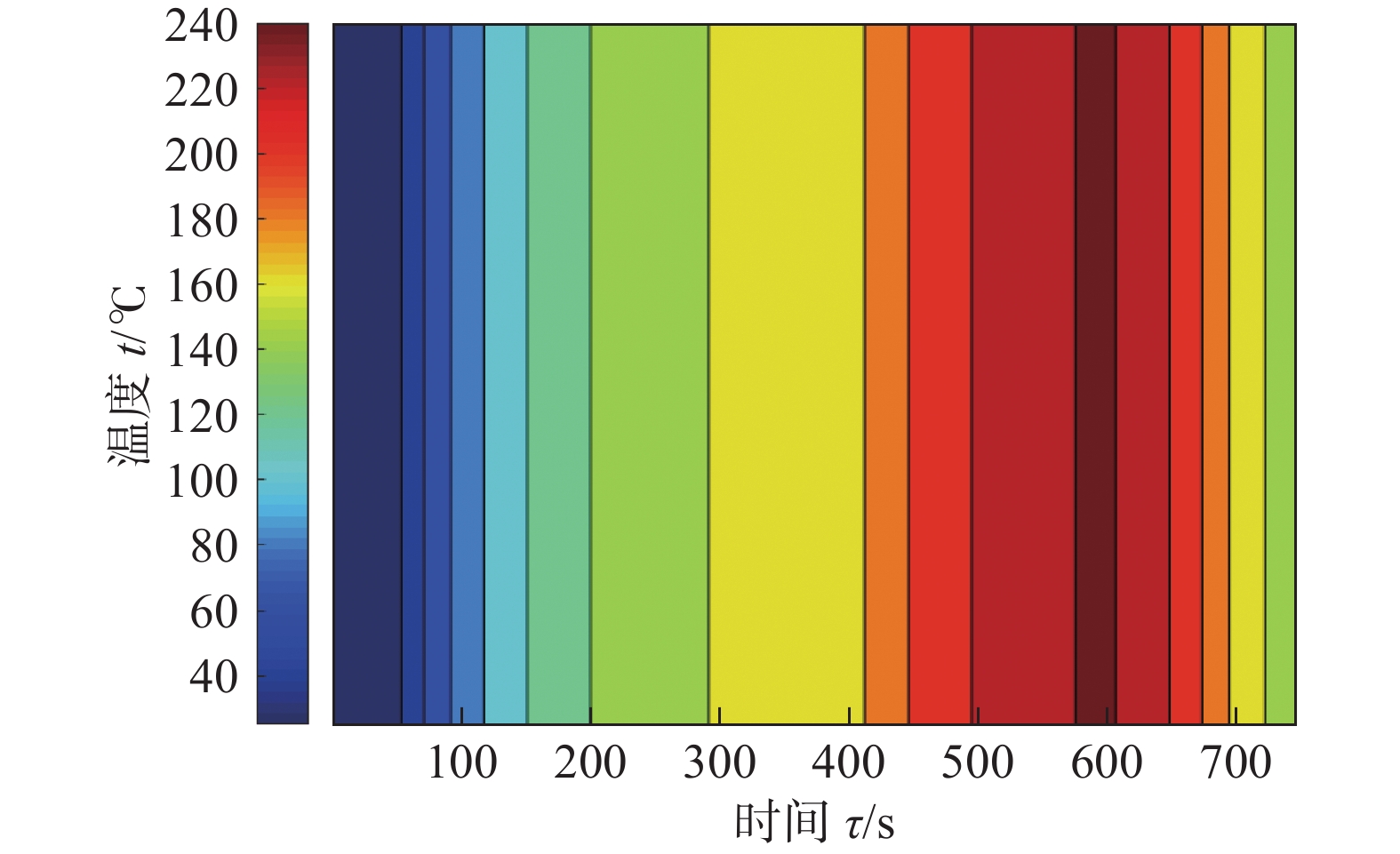
![]()
图 1 回焊炉温度场温度分布曲线
Figure 1. Temperature distribution curve of reweld furnace temperature field
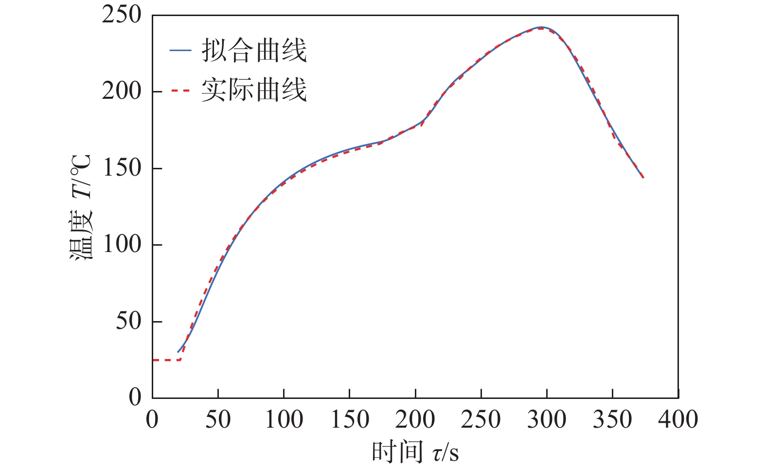
![]()
图 2 模拟炉温曲线与实测温度曲线对比
Figure 2. Comparison between simulated furnace temperature curve and measured temperature curve
![]()
图 3 电路板焊接中心温度分布图
Figure 3. Temperature distribution diagram of circuit board welding center
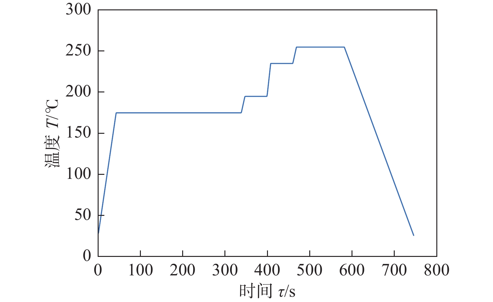
表 1 回焊炉各温区长度和温度
Table 1 Length and temperature of each temperature zone in rewelding furnace
区域 长度l/cm 温度T/℃ 炉前 25 25 1 ~ 5 172.5 175 6 30.5 195 7 30.5 235 8 ~ 9 66 255 10 ~ 11 66 25 炉后 25 25 间隙 5 —  下载: 导出CSV
表 2 传送带速度需满足的制程界限
Table 2 Process limits for conveyor speed
炉温曲线峰值温度 T/℃ 焊接中心升温过程中位于
[150 ℃, 190 ℃]温度区间的时间 τt/s焊接中心温度变化速率(dt/di)/(℃·s−1) 焊接中心温度位于[217 ℃,tmax]温度
区间的时间 τt/s240 $\leqslant $ tmax$\leqslant $ 250$\dfrac{\text{d}t}{\text{d}\tau } > 0$
且60 < τt∈[150 ℃,190 ℃]$ < 120 $ −3 $ < \dfrac{\text{d}t}{\text{d}\tau } < $ 340 $\leqslant $ ${\tau _{t \in [217\;{\text{℃} },\;{ { {t_{\max } }]} }} }$ $\leqslant $ 90
下载: 导出CSV
表 3 3种不同优化情况结果
Table 3 Results of three different optimization conditions
目标参数 过炉速度v/(cm·min−1) 加热因子
Scover最小加热因子min (Scover) 94.05 1 027.80 最大过炉速度max (v ) 95.626 2 2 931.56 最小加热因子min (Scover)和
最大过炉速度max (v )95.55 1 753.04
下载: 导出CSV
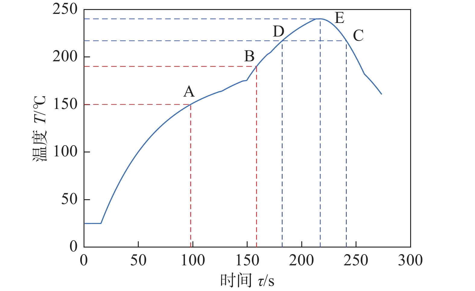
表 4 优化后炉温曲线内特殊点坐标值
Table 4 Coordinate values of special points in the furnace temperature curve after optimization
点 坐标 点 坐标 A (98.50,150.11) D (183.00,216.97) B (159.00,190.02) E (219.00,240.01) C (242.50,217.36)
下载: 导出CSV
表 5 优化后获得的最优温区温度值
Table 5 Optimal temperature value of temperature zone obtained after optimization
温区 优化后温度T0/℃ 温区 优化后温度T0/℃ 1~5 184.34 8~9 264.81 6 199.35 10~11 25 7 239.07
下载: 导出CSV
-
[1] Luo X D, Wang Z S, Deng W H. Optimization model design for temperature curve of reflow furnace[J]. Journal of Physics: Conference Series, 2021, 1802(2): 022020.
[2] Harrison M R, Vincent J H, Steen H A H. Lead-free reflow soldering for electronics assembly[J]. Soldering & Surface Mount Technology, 2001, 13(3): 21 − 38.
[3] 陈恒宇,丁唯一,殷寰宇,等.基于量子遗传算法的回焊炉参数设定[J].重庆理工大学学报(自然科学),2021,35(9):248-255. Chen Hengyu, Ding weiyi, Yin Huanyu, et al. Back-welding furnace parameter setting based on the quantum genetic algorithm [J]. Journal of Chongqing University of Technology (Natural Science), 2021,35 (9): 248-255.
[4] 郑风景. 基于六西格玛方法的SMT回流焊产品质量控制研究[D]. 天津: 天津科技大学, 2014. Zheng Fengjing. Research on quality control of SMT reflow soldering process based on the six sigma approach[D]. Tianjin: Tianjin University of Science & Technology, 2014.
[5] 徐宗煌,徐剑莆,李世龙,等. 回焊炉电路板焊接炉温曲线优化模型[J]. 沈阳大学学报(自然科学版), 2021,33(3):279-286. Xu Zonghuang, Xu Jianpu, Li Shilong, et al. Optimization model of welding furnace temperature curve of back-welding furnace circuit board [J]. Journal of Shenyang University (Natural Science Edition), 2021,33 (3): 279-286.
[6] 焦进莉. 六西格玛方法在提升SMT回流焊过程质量中的应用研究[D]. 上海: 上海交通大学, 2011. Jiao Jinli. The application study of six sigma approach on quality improvement of SMT reflow process. [D]. Shanghai: Shanghai Jiaotong University, 2011.
[7] 李楠, 王晓杰, 杜咏昊. 最优炉温曲线与确定其工艺参数问题[J]. 电子测试, 2021(1): 48 − 50. doi: 10.3969/j.issn.1000-8519.2021.01.017 Li Nan, Wang Xiaojie, Du Yonghao. Optimal furnace temperature curve and determination of process parameters[J]. Electronic Test, 2021(1): 48 − 50. doi: 10.3969/j.issn.1000-8519.2021.01.017
[8] 王明泉, 周心如, 李博文. 基于热力学原理的炉温曲线调控模型[J]. 科学技术创新, 2021(1): 1 − 3. doi: 10.3969/j.issn.1673-1328.2021.01.002 Wang Mingquan, Zhou Xinru, Li Bowen. Control model of furnace temperature curve based on thermodynamic principle[J]. Scientific and Technological Innovation, 2021(1): 1 − 3. doi: 10.3969/j.issn.1673-1328.2021.01.002
[9] 方灏航. 基于传热学的炉温曲线研究[J]. 现代信息科技, 2020, 4(20): 18 − 22. Fang Haohang. Furnace temperature curve research based on heat transfer[J]. Modern Information Technology, 2020, 4(20): 18 − 22.
[10] Lei Q Y, Zhang Z Y, Zhuo S Y, et al. Research on furnace temperature curve based on heat convection and heat radiation[J]. E3S Web of Conferences, 2021, 233(9): 04004.
[11] Wealer B, Bauer S, Hirschhausen C V, et al. Investing into third generation nuclear power plants—Review of recent trends and analysis of future investments using Monte Carlo Simulation[J]. Renewable and Sustainable Energy Reviews, 2021, 143: 110836.
[12] 祝胜光, 杨安全. 小型回流焊炉温度PID控制算法研究[J]. 机械工程与自动化, 2012(1): 138 − 140. doi: 10.3969/j.issn.1672-6413.2012.01.054 Zhu Shengguang, Yang Anquan. Study on the temperature PID control algorithm of small reflux welding furnace[J]. Mechanical Engineering & Automation, 2012(1): 138 − 140. doi: 10.3969/j.issn.1672-6413.2012.01.054
[13] Sun J, Wu X J, Palade V, et al. Convergence analysis and improvements of quantum-behaved particle swarm optimization[J]. Information Sciences, 2012, 193: 81 − 103.
[14] Wang F, Zhang H, Zhou A M. A particle swarm optimization algorithm for mixed-variable optimization problems[J]. Swarm and Evolutionary Computation, 2021, 60: 100808. doi: 10.1016/j.swevo.2020.100808
[15] 冯茜, 李擎, 全威,等. 多目标粒子群优化算法研究综述[J]. 工程科学学报, 2021, 43(6): 745-753. Feng Qian, Li Qing, Quan Wei, et al. Overview of multiobjective particle swarm optimization algorithm[J]. Chinese Journal of Engineering, 2021, 43(6): 745-753.
[16] Zhang D G, Wang J X, Fan H R, et al. New method of traffic flow forecasting based on quantum particle swarm optimization strategy for intelligent transportation system[J]. International Journal of Communication Systems, 2020, 34(1): e4647.
[17] 邱幸运. 基于量子粒子群算法的工程项目多目标优化研究[D]. 邯郸: 河北工程大学, 2019. Qiu Xingyun. Multi-objective optimization of engineering projects based on quantum-behaved particle swarm optimization [D]. Handan: Hebei University of Engineering, 2019.
[18] Gao J G, Wu Y P, Ding H. Optimization of a reflow soldering process based on the heating factor[J]. Soldering & Surface Mount Technology, 2007, 19(1): 28 − 33.
[19] Campo A, Arici M. Lucid characterization of unsteady heat conduction in large, square crossbars and cubes subject to uniform surface heat flux by way of “quasi-steady” Helmholtz equations[J]. Thermal Science and Engineering Progress, 2020, 20: 100724. doi: 10.1016/j.tsep.2020.100724
[20] Yang Z. Investigation on the thermal problems of wet clutches for the tracked DCT vehicle during the launching process[J]. IOP Conference Series Materials Science and Engineering, 2020, 892: 012046. doi: 10.1088/1757-899X/892/1/012046
[21] 郭安柱, 马永志. 空调房数学建模与仿真[J]. 科学技术创新, 2020(12): 120 − 122. Guo Anzhu, Ma Yongzhi. Mathematical modeling and simulation of air-conditioned room[J]. Scientific and Technological Innovation, 2020(12): 120 − 122.
[22] Gao J G, Wu Y P, Ding H, et al. Thermal profiling: a reflow process based on the heating factor[J]. Soldering & Surface Mount Technology, 2008, 20(4): 20 − 27.
[23] 李岩, 赵立博, 张伟, 等. 对回流焊炉温度设定的分析与优化[J]. 船电技术, 2010, 30(7): 44 − 46. doi: 10.3969/j.issn.1003-4862.2010.07.012 Li Yan, Zhao Libo, Zhang Wei, et al. Analysis and optimization on the temperature settings of reflow soldering furnace[J]. Marine Electric & Electronic Engineering, 2010, 30(7): 44 − 46. doi: 10.3969/j.issn.1003-4862.2010.07.012
[24] 高金刚. 表面贴装工艺生产线上回流焊曲线的优化与控制[D]. 上海: 上海交通大学, 2007. Gao Jingang. Optimization and control of reflow soldering profile in SMT line[D]. Shanghai: Shanghai Jiaotong University, 2007.
[25] Zhao Y X, Song X T, Wang F, et al. Multiobjective optimal dispatch of microgrid based on analytic hierarchy process and quantum particle swarm optimization[J]. Global Energy Interconnection, 2020, 3(6): 562 − 570. doi: 10.1016/j.gloei.2021.01.008
[26] Wang R J. Multi-objective configuration optimization method for a diesel-based hybrid energy system[J]. Energy Reports, 2020, 6: 2146 − 2152. doi: 10.1016/j.egyr.2020.08.004
[27] Hou H, Liu P, Xiao Z F, et al. Capacity configuration optimization of standalone multi-energy hub considering electricity, heat and hydrogen uncertainty[J]. Energy Conversion and Economics, 2021, 2(3): 122 − 132.
-
期刊类型引用(8)
1. 孙康,肖笑,石红信,符成学,内田成明. 钛合金电弧增材制造温度与残余应力数值模拟. 材料热处理学报. 2025(04): 202-210 .  百度学术
百度学术
2. 李敬勇,李超然,徐育烺,钱鹏. 层间温度对CMT电弧增材制造2Cr13不锈钢薄壁件成形及组织和性能影响. 焊接. 2024(02): 43-50 . 百度学术
3. 张云舒,吴斌涛,赵昀,丁东红,潘增喜,李会军. 电弧熔丝增材制造传热传质数值模拟研究现状与展望. 机械工程学报. 2024(08): 65-80 . 百度学术
4. 张云舒,郑登勇,邵丹丹,徐晖,徐仁,吴斌涛. 层间强制冷却对电弧熔丝增材制造钛合金温度场和流场的影响. 西北工程技术学报. 2024(03): 199-205+213 . 百度学术
5. 王磊磊,吕飞阅,高转妮,虞文军,高川云,占小红. 电弧增材制造2319铝合金交叉桁条结构微观组织与拉伸性能研究. 机械工程学报. 2023(01): 267-277 . 百度学术
6. 贾金龙,张佳,杜明科,蒋成燕,冯毅. SUS304奥氏体不锈钢TIG焊电弧增材制造工艺优化. 机械制造文摘(焊接分册). 2023(01): 1-6 . 百度学术
7. 邸艳艳,胡仁志,熊逸博,郑志镇,李建军. 电弧熔丝增材制造316L的温度场仿真及对基体的影响. 电焊机. 2022(01): 63-67 . 百度学术
8. 刘理想,柏兴旺,周祥曼,张海鸥. 电弧增材制造多层单道堆积的焊道轮廓模型函数. 焊接学报. 2020(06): 24-29+36+98 . 本站查看
其他类型引用(12)


计量
- 文章访问数: 219
- HTML全文浏览量: 35
- PDF下载量: 29
- 被引次数: 20
