
Study on microstructure and comprehensive properties of SAF2205 duplex stainless steel multilayer and multipass welded joint
-
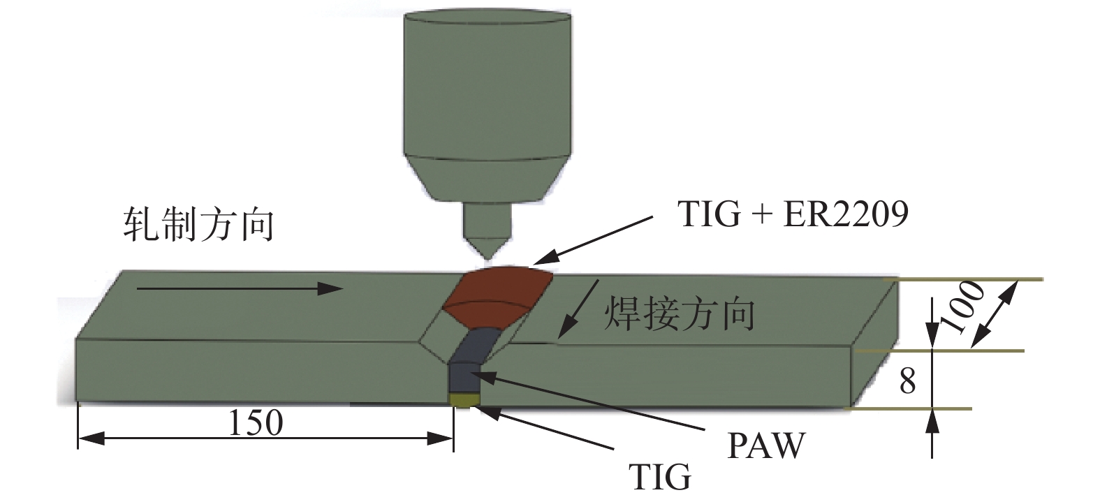
摘要: 采用TIG/PAW复合焊接对SAF2205双相不锈钢进行多层多道焊接,并进行固溶处理,利用OM、SEM、EBSD等设备,通过电化学腐蚀、拉伸、冲击等试验研究焊缝组织演变与综合性能的关系. 结果表明:TIG填丝盖面焊接处的焊缝铁素体含量为70.5%,由于添加焊丝的原因,焊缝奥氏体晶粒最大为177 μm2,大于母材142 μm2;PAW焊缝铁素体含量为65.4%,因为焊接顺序的不同,后续焊接对焊缝有加热作用,导致铁素体含量最少;在TIG焊缝中,热输入较大,导致铁素体晶粒粗化最大为8 147 μm2,大于母材264 μm2,导致奥氏体形核位置减少,奥氏体仅为3.96%. 在1 050 ℃固溶处理60 min后焊缝两相接近1∶1,并且奥氏体趋于均匀化,随固溶时间的延长耐腐蚀性增强. 焊态焊缝抗拉强度大于846 MPa,拉伸断裂均在母材. 焊缝冲击吸收能量为144 J,小于母材(156 J),焊缝表现为复合断裂.
-
关键词:
- SAF2205双相不锈钢 /
- 复合焊接TIG/PAW /
- 微观组织 /
- 固溶处理 /
- 综合性能
Abstract: TIG/PAW composite welding was used to weld SAF2205 duplex stainless steel with three layers and three channels, and solution treatment was carried out. OM, SEM, EBSD and electrochemical corrosion, tensile, impact and other experiments were used to study the relationship between the microstructure evolution of the weld and mechanical properties, corrosion resistance. The results show that the ferrite content of TIG filler wire weld is 70.5%, and the austenite grain of TIG filler wire weld is the largest (177 μm2), which is larger than that of base metal (142 μm2) due to the addition of welding wire. The ferrite content of PAW weld is 65.4%. Due to the different welding sequence, subsequent welding has a heating effect on the weld, resulting in the least ferrite content. In TIG weld, the large heat input results in the coarsening of ferrite grain (8 147 μm2), which is larger than the base metal (264 μm2), resulting in the reduction of austenite core location and only 3.96% austenite. Due to the difference of deformation mechanism and stacking fault energy between austenite and ferrite, the number of ferrite sub-grains is larger than that of austenite, while the number of recrystallized grains and high-angle grain boundary is smaller than that of austenite. After solution treatment at 1 050 ℃ for 60 min, the two phases of the weld are close to 1∶1, and the austenite tends to homogenize, and the corrosion resistance increases with the extension of solution time. The tensile fractures were all in the base metal, and the tensile strength of the weld were greater than 846 MPa. The weld impact energy is 144 J, less than the base metal (156 J), and the weld shows composite fracture. -
0. 序言
铝合金在密度、强度和耐蚀上有综合优势,激光焊有能量集中、变形小、焊接质量高等优点,铝合金激光焊在国防、军工、航空航天、铁道等重要工业部门获得了广泛应用,例如其可应用于高速列车车厢等重要焊接结构的连接[1]. 但铝合金激光焊时由于保护不良等易在焊缝中产生气孔等缺陷,这些缺陷的存在将会形成重大的安全隐患,因此为保障高速列车的安全运行,亟需开展铝合金激光焊件的快速无损检测及缺陷空间定位研究,从而为重要焊接结构的焊接工艺制订和接头完整性评价奠定良好基础.
国内外开展焊件射线图像缺陷分割、识别和分类方面的研究较多,而开展焊件缺陷空间定位和空间分布特征方面的研究较少[2-4]. 一般情况下,利用X射线成像技术对焊件内部缺陷进行定位,普遍采用两次曝光以获得缺陷深度方向的位置信息[5]. 平移视差法由于采用移动射线源或工件等方式,存在射线源或工件移动困难,且平移距离难以准确测量等状况,使其缺陷定位的操作难度大,误差传递亦大[6-7]. 在平移视差法基础上,迟大钊等人[8]利用旋转视差法对普通对接接头焊件内部人工缺陷进行了深度定位,其精度比平移视差法有较大提高,但在缺陷深度定位中仍需借助铅标记点. 石端虎等人[9-12]利用多视角成像方法,实现了工字形焊件内部缺陷的空间定位和可视化. 该法不需借助铅标记点,而是利用被检焊接结构的几何特点确定定位特征点,实现了批量缺陷的空间定位,且提高了定位精度和检测效率. 目前T形接头角焊缝中缺陷空间定位及空间分布特征的研究尚未见报道,因此开展该方面的研究具有极为重要的理论研究意义和实际应用价值.
1. 缺陷空间定位模型建立
图1为T形接头铝合金激光焊件结构示意图. 翼板厚度和腹板宽度均为2.0 mm,焊脚尺寸为1.5 mm.
采用225 kV微焦点X射线检测系统对T形接头焊件左右旋转45°进行射线检测,获得了其左右旋转的X射线检测图像,见图2,其中图2a和图2b中的白色影像为焊件中的气孔缺陷. 图像大小为1 024像素 × 1 024像素.
![]() 图 2 焊件检测图像Figure 2. Detection images of weldment. (a) right-turning image; (b) left-turning image
图 2 焊件检测图像Figure 2. Detection images of weldment. (a) right-turning image; (b) left-turning image选用角焊缝直角的角平分线(面)为定位特征点,根据射线检测图像中各部分之间的几何关系,建立了T形接头焊件角焊缝中缺陷深度和偏移量的数学模型. 图3和图4分别为缺陷深度和偏移量数学模型建立的示意图.
缺陷深度数学模型,即
$$h = \sqrt 2 {d_{\rm{l}}} - \left(x + \frac{W}{2}\right) + \delta $$ (1) 缺陷偏移量数学模型,即
$$x = \frac{{{d_{\rm{l}}} - {d_{{r}}}}}{{\sqrt 2 }}$$ (2) 式中:h为缺陷深度,即缺陷到T形接头焊件翼板下表面的距离(mm);d
l为焊件右转时缺陷到定位特征点的投影距离(mm);dr为焊件左转时缺陷到定位特征点的投影距离(mm);W为腹板宽度(mm);δ为翼板厚度(mm);x为缺陷偏移量,即缺陷偏移焊件腹板中心线的距离(mm). 当x > 0时缺陷位于焊件腹板中心线的右侧;当x = 0时缺陷位于焊件腹板中心线上;当x < 0时缺陷位于焊件腹板中心线的左侧.
2. 缺陷空间位置数据提取及可视化
2.1 缺陷分割
图2中标出了焊缝所在区域,该区域中的白色影像为气孔缺陷. 采用形态学方法对小波去噪后的射线检测图像进行了背景模拟,而后结合背景相减和阈值分割等操作实现了射线检测图像的缺陷分割,分割结果见图5,图5中的白色影像为分割出的气孔缺陷.
![]() 图 5 缺陷分割结果Figure 5. Segmentation result of defects. (a) right-turning image; (b) left-turning image
图 5 缺陷分割结果Figure 5. Segmentation result of defects. (a) right-turning image; (b) left-turning image2.2 定位特征点获取
根据射线衰减规律,射线检测图像上灰度分布与射线穿透焊件的厚度变化规律应相符,因此可通过射线检测图像的线灰度分布特征分析获取定位特征点的位置.图6为射线穿透焊件的厚度变化示意图,图中O点为焊件缺陷定位数学模型中的定位特征点位置. 位置1、位置3是厚度变化最为明显位置,分别为射线穿透焊件最薄处和最厚处,相应地在射线检测图像的线灰度分布曲线上表现为灰度值最大处和最小处. 根据焊件各部分间的几何关系,可通过位置1或位置3与定位特征点之间的水平距离获取定位特征点位置. 因为检测图像上位置1处灰度值较高,且受射线检测工艺参数的影响较大,所以选择位置3获取定位特征点位置. 该方法先搜寻出射线检测图像中灰度值最小处(位置3),由几何关系可知,从位置3向左平移
$3.5\Big/\sqrt 2$ mm即可获取定位特征点位置.![]() 图 6 穿透厚度变化示意图Figure 6. Schematic of penetration thickness changing. (a) ray path; (b) thickness changing
图 6 穿透厚度变化示意图Figure 6. Schematic of penetration thickness changing. (a) ray path; (b) thickness changing2.3 缺陷自动对应
在缺陷分割基础上,需对焊件右左转射线检测图像中的批量缺陷进行自动对应,而后方可实现缺陷空间位置数据的自动提取. 确定的缺陷自动对应准则如下:提取出焊件右左转射线检测图像中缺陷的中心位置,并分别计算出右左转射线检测图像中缺陷的中心位置距图像上端的距离d1,d2. 右左转图像中缺陷距图像上端距离之差|d1 − d2|不超过3个像素点,即可判定为同一缺陷.
2.4 缺陷空间位置数据自动提取
图7为T形接头焊件射线检测图像中某行通过气孔缺陷的线灰度分布曲线,定位特征点(O处)至灰度值突变位置(缺陷)之间距离为投影距离[10]. 将自动提取的投影距离代入缺陷偏移量和深度的数学模型,可计算得出缺陷偏移量和深度. 缺陷沿焊缝纵向分布可通过对检测图像的处理获得,从而可自动提取缺陷的空间位置数据.
采用提出的方法自动提取了T形接头焊件角焊缝内部缺陷的深度、偏移量及距焊缝一端距离等空间位置数据. 图8为自动提取的焊件内部缺陷的空间位置数据( mm),图中对各列数据进行了标注. 该焊件中共自动提取了27个气孔缺陷.
2.5 缺陷可视化
为了直观地显示T形接头焊件角焊缝内部缺陷的空间位置,在建立焊件三维模型的基础上,对自动提取的缺陷空间位置数据进行了可视化,见图9.
3. 缺陷空间分布特征
对多个实际焊件进行了射线检测,并自动提取了84个缺陷的空间位置数据. 统计了缺陷偏移量、缺陷深度、缺陷沿焊缝纵向分布和缺陷半径等空间位置信息,进而可确定缺陷的空间分布特征. 石端虎等人[12]采用破坏性试验方法对穿透型T形接头焊件中缺陷深度、偏移量数学模型进行了验证,验证结果适用于文中研究,但缺陷深度的验证误差约为5%,下一步将考虑通过焊件X射线检测图像模拟开展缺陷空间定位模型的无损伤验证.
缺陷空间分布特征见图10. 图10a为缺陷偏移量及频数统计,缺陷偏移量在[−1.5 1] mm范围内,缺陷偏移量小于0的频数为62次,占总样本的73.8%,即缺陷大多分布在腹板中心线左侧,且在[−0.5 0] mm范围内气孔密集出现;图10b为缺陷深度及频数统计,缺陷深度大多位于[1.8 2.5] mm范围内,此范围内缺陷频数为72次,占总样本的85.7%,这表明有近86%的缺陷集中分布在翼板与腹板的结合面位置,其对焊接接头的性能影响较大;图10c为缺陷半径及频数统计,缺陷半径在[0 0.51] mm范围内;由图10d可知缺陷沿焊缝纵向呈随机分布.
![]() 图 10 缺陷空间分布特征Figure 10. Spatial distribution feature of defects. (a) defects deviation and frequency; (b) defects depth and frequency; (c) defects radius and frequency; (d) defects longitudinal distribution and frequency
图 10 缺陷空间分布特征Figure 10. Spatial distribution feature of defects. (a) defects deviation and frequency; (b) defects depth and frequency; (c) defects radius and frequency; (d) defects longitudinal distribution and frequency4. 结论
(1) 基于多视角成像方法,通过左右旋转焊件45°,获得了焊件左右转的两幅X射线检测图像. 借助检测图像中各部分间的几何关系,建立了T形接头焊件角焊缝中缺陷深度和偏移量的数学模型.
(2) 提出了X射线检测图像中缺陷分割、缺陷自动对应准则和投影距离自动提取算法,自动提取了批量缺陷空间位置数据,实现了缺陷空间位置数据的可视化.
(3) 统计分析了自动提取的84个缺陷的空间分布特征,可为该类焊件的快速无损检测和结构完整性评价奠定良好基础,并可推广至对接接头及其它接头类型,工程应用前景广阔.
-
![]()
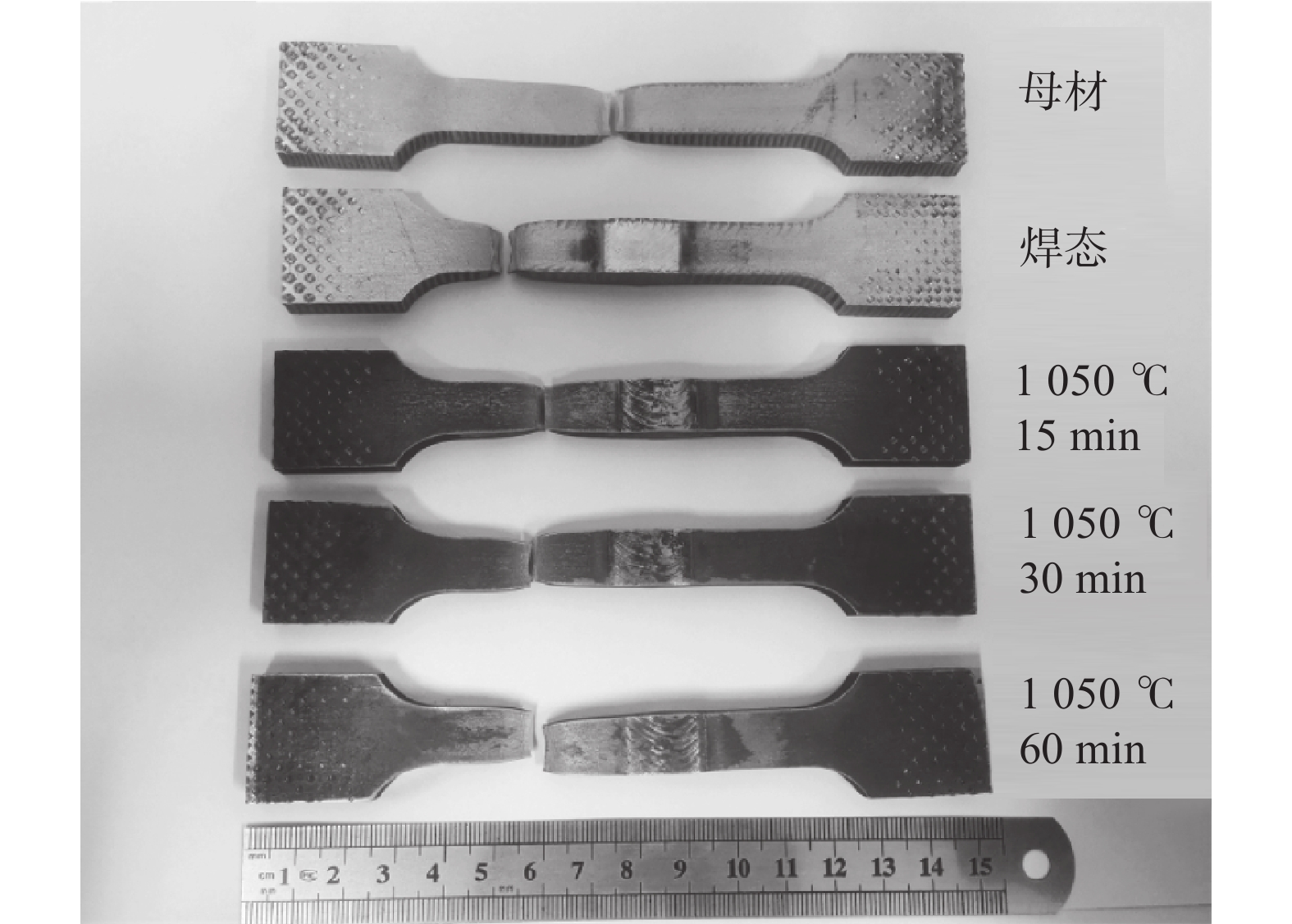
图 2 冲击示意图和横向拉伸示意图(mm)
Figure 2. Charpy test diagram and transverse tensile diagram. (a) charpy test diagram; (b) transverse tensile diagram
![]()
图 3 SAF2205双相不锈钢母材微观组织
Figure 3. Microstructure of SAF2205 duplex stainless steel base material. (a) SEM; (b) EBSD
![]()
图 4 SAF2205双相不锈钢焊缝横截面形貌
Figure 4. Cross section morphology of SAF2205 duplex stainless steel weld
![]()
图 5 焊缝局部微观组织特征
Figure 5. Microstructure characteristics of the weld. (a) the OM morphologie of TIG filler wire welding seam; (b) the OM morphologie of PAW welding seam; (c) the OM morphologie of TIG welding seam; (d) the IPF diagram of TIG filler wire welding seam; (e) the IPF diagram of PAW welding seam; (f) the IPF diagram of TIG welding seam; (g) the two-phase distribution diagram of TIG filler wire welding seam; (h) the two-phase distribution diagram of PAW welding seam; (i) the two-phase distribution diagram of TIG welding seam
![]()
图 6 SAF2205双相不锈钢1 050 ℃固溶处理后焊缝微观形貌
Figure 6. Microstructure of welding seam after solution treatment at 1 050 ℃ of SAF2205 duplex stainless steel. (a) TIG filler wire welding seam after solution treatment for 15 min; (b) PAW welding seam after solution treatment for 15 min; (c) TIG welding seam after solution treatment for 15 min; (d) TIG filler wire welding seam after solution treatment for 30 min; (e) PAW welding seam after solution treatment for 30 min; (f) TIG welding seam after solution treatment for 30 min; (g) TIG filler wire welding seam after solution treatment for 60 min; (h) PAW welding seam after solution treatment for 60 min; (i) TIG welding seam after solution treatment for 60 min
![]()
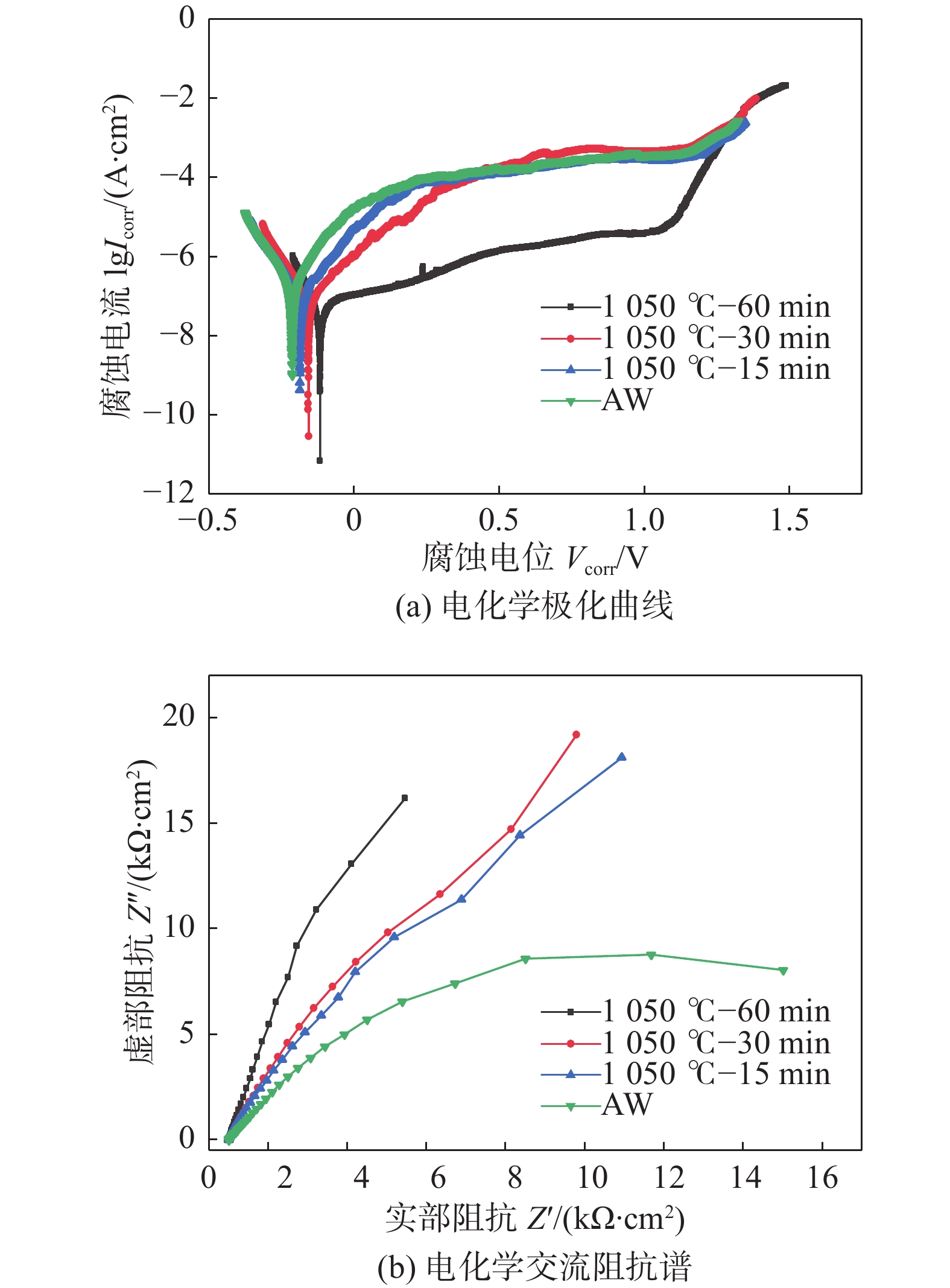
图 7 SAF2205双相不锈钢在1 mol/L NaCl腐蚀
Figure 7. Corrosion of SAF2205 duplex stainless steel in 1 mol/L NaCl. (a) electrochemical polarization curve; (b) electrochemical impedance spectroscop
![]()
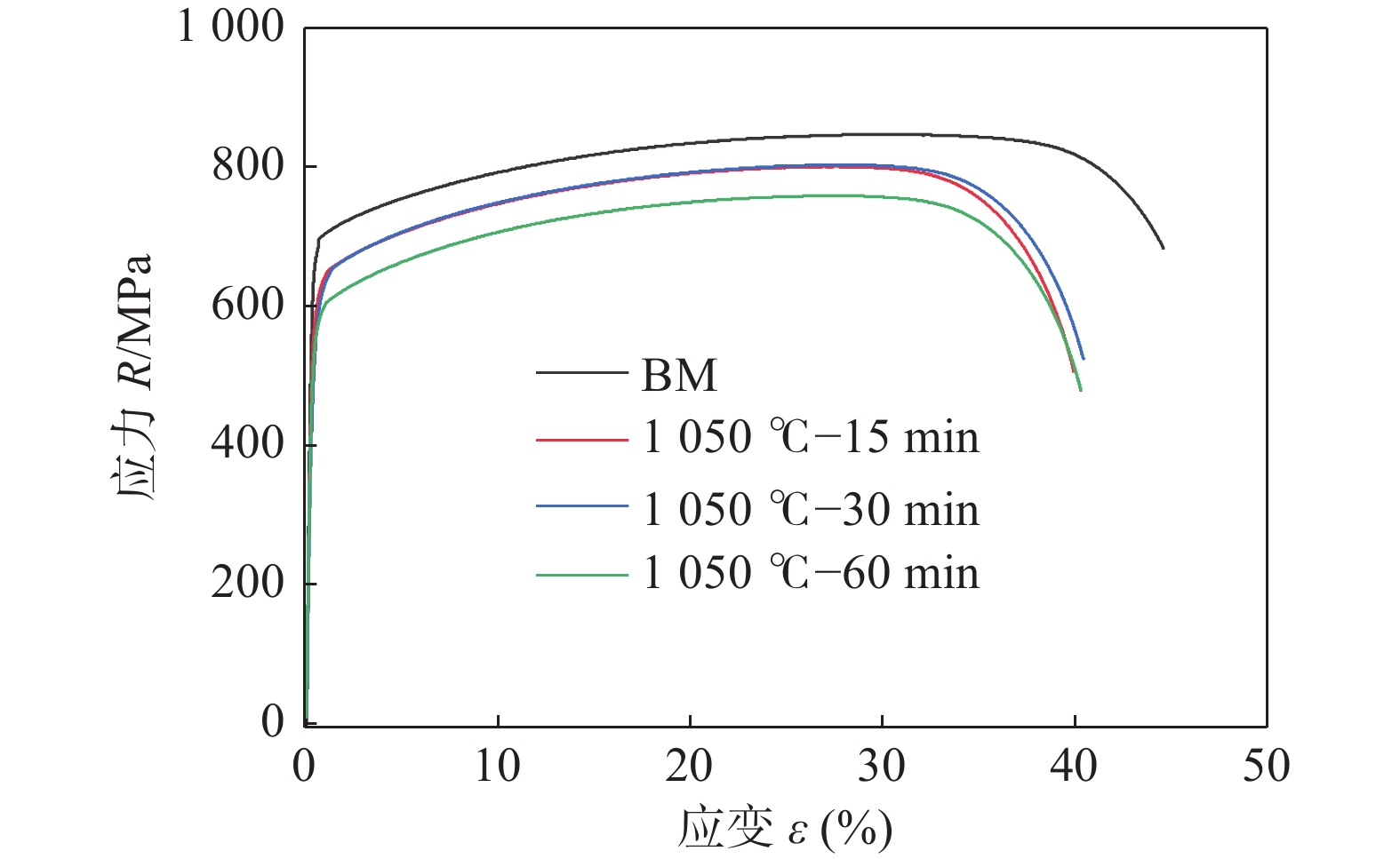
图 8 SAF2205双相不锈钢工程应力应变曲线
Figure 8. Engineering stress-strain curve of SAF2205 duplex stainless steel
![]()
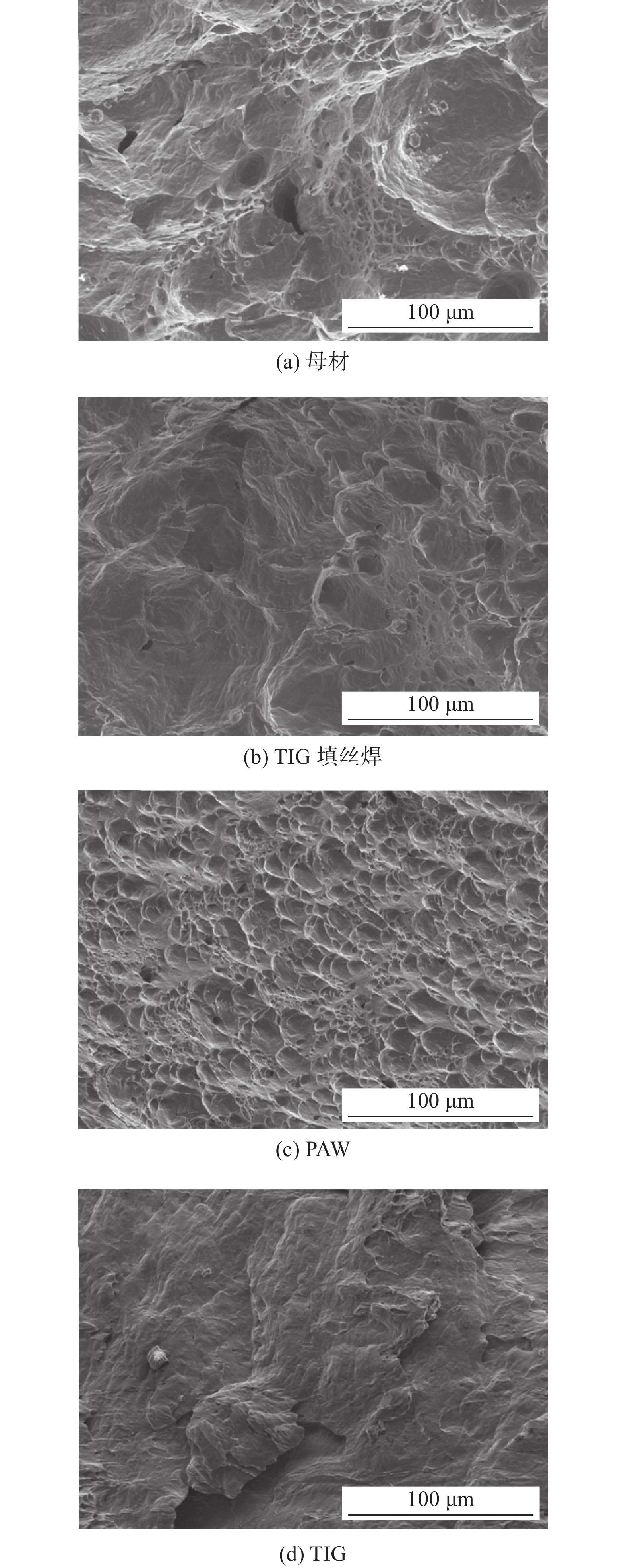
图 10 SAF2205双相不锈钢焊缝与母材冲击断口形貌
Figure 10. Impact fracture morphology of SAF2205 dual-phase stainless steel weld and base metal. (a) BM; (b) TIG filler wire weld; (c) PAW (d) TIG
表 1 SAF2205化学成分(质量分数,%)
Table 1 Chemical constituents of SAF2205
C Mn Si Mo Cr Ni N S P Fe 0.016 0.82 0.36 3.12 22.48 5.46 0.16 0.001 0.024 余量  下载: 导出CSV
表 2 1 050 ℃固溶处理后焊缝两相比例(γ∶α)
Table 2 Two-phase ratio of solid solution treated welds at 1 050 ℃
固溶处理时间t/min TIG + ER PAW TIG 15 30.20∶69.80 34.25∶65.25 19.02∶80.98 30 38.66∶61.34 41.11∶58.59 31.75∶68.25 60 47.08∶52.92 52.42∶47.58 40.98∶59.02
下载: 导出CSV
表 3 SAF2205双相不锈钢电化学腐蚀参数
Table 3 Electrochemical corrosion parameters of SAF2205 duplex stainless steel
固溶处理时间
t/min腐蚀速度
vcorr /(g∙m−2∙h−1)腐蚀电流
Icorr /(1 × 10−5 A∙cm2)腐蚀电位
Vcorr /V15 1.015 462 2.871 −0.1163 30 3.045 871 4.684 −0.1567 60 3.658 807 4.628 −0.1868 焊态 4.794 887 9.967 −0.2124
下载: 导出CSV
表 4 SAF2205双相不锈钢焊缝和母材的拉伸性能
Table 4 Tensile properties of SAF2205 duplex stainless steel weld and base metal
固溶处理时间t/min 屈服强度ReL/MPa 抗拉强度Rm/MPa 断后伸长率
A/(%)母材 685 846 44.40 15 639 800 39.82 30 644 803 40.44 60 598 758 40.00
下载: 导出CSV
-
[1] Moteshakker A, Danaee I. Microstructure and corrosion resistance of dissimilar weld-joints between duplex stainless steel 2205 and austenitic stainless steel 316L[J]. Journal of Materials Science & Technology, 2016, 32(6): 282 − 290.
[2] Satyanarayana V V, Reddy G M, Mohandas T. Dissimilar metal friction welding of austenitic-ferritic stainless steels[J]. Journal of Materials Processing Technology, 2005, 160(2): 128 − 137. doi: 10.1016/j.jmatprotec.2004.05.017
[3] Verma j, Taiwade R V. Effect of welding processes and conditions on the microstructure, mechanical properties and corrosion resistance of duplex stainless steel weldments—A review[J]. Journal of Manufacturing Processes, 2017, 25: 134 − 152. doi: 10.1016/j.jmapro.2016.11.003
[4] Badji R, Bouabdallah M, Bacroix B. Phasetransformation and mechanical behavior in annealed 2205 duplex stainless steelwelds[J]. Materials Characterization, 2008, 59: 447 − 453. doi: 10.1016/j.matchar.2007.03.004
[5] Kim D C, Ogura T, Yamashita S. Computer prediction of α/γ phase fraction in multi-pass weld of duplex stainless steel and microstructural improvement welding process[J]. Materials and Design, 2020, 196: 109154. doi: 10.1016/j.matdes.2020.109154
[6] Woo W, An G B, Kingston E J. Through-thickness distributions of residual stresses in two extreme heat-input thick welds: A neutron diffraction, contour method and deep hole drilling study[J]. Acta Materialia, 2013, 61(10): 3564 − 3574. doi: 10.1016/j.actamat.2013.02.034
[7] Gao S, Geng S, Jiang P. Numerical analysis of the deformation behavior of 2205 duplex stainless steel TIG weld joint based on the microstructure and micro-mechanical properties[J]. Materials Science & Engineering A, 2021, 815: 141303.
[8] Shen J L, Wei Z J, Zhu X R. Microstructure evolution and mechanical properties of flash butt-welded Inconel 718 joints[J]. Materials Science & Engineering A, 2018, 718: 34 − 42.
[9] Cui S W, Shi Y H, Sun K. Microstructure evolution and mechanical properties of keyhole deep penetration TIG welds of S32101 duplex stainless steel[J]. Materials Science & Engineering A, 2018, 709(2): 214 − 222.
[10] Toth T, Krasnorutskyi S, Hensel J. Electron beam welding of 2205 duplex stainless steel using pre-placed nickel-based filler material[J]. International Journal of Pressure Vessels and Piping, 2021, 191: 104354. doi: 10.1016/j.ijpvp.2021.104354
[11] Lai R, Cai Y, Wu Y. Influence of absorbed nitrogen on microstructure and corrosion resistance of 2205 duplex stainless steel joint processed by fiber laser welding[J]. Journal of Materials Processing Technology, 2016, 231: 397 − 405. doi: 10.1016/j.jmatprotec.2016.01.016
[12] Zhang Z Q, Jing H Y, Xua L Y. Effect of post-weld heat treatment on microstructure evolution and pitting corrosion resistance of electron beam-welded duplex stainless steel[J]. Corrosion Science, 2018, 141(15): 30 − 45.
[13] Yang Y Z, Wang Z Y, Tan H. Effect of a brief post-weld heat treatment on the microstructure evolution and pitting corrosion of laser beam welded UNS S31803 duplex stainless steel[J]. Corrosion Science, 2012, 65: 472 − 480. doi: 10.1016/j.corsci.2012.08.054
[14] Jastej S, Shahi A S. Metallurgical and corrosion characterization of electron beam welded duplex stainless steel joints[J]. Journal of Manufacturing Processes, 2020, 50: 581 − 595. doi: 10.1016/j.jmapro.2020.01.009
[15] Ku J S, Ho N J, Tjong S C. Properties of electron beam welded SAF 2205 duplex stainless steel[J]. Journal of Manufacturing Processing Technology, 1997, 63(1-3): 770 − 775. doi: 10.1016/S0924-0136(96)02721-5
[16] Sieurin H, Sandström R. Austenite reformation in the heat-affected zone of duplex stainless steel 2205[J]. Materials Science & Engineering A, 2006, 418(1-2): 250 − 256. doi: 10.1016/j.msea.2005.11.025
[17] Mourad A H I, Khourshid A, Sharef T. Gas tungsten arc and laser beam welding processes effects on duplex stainless steel 2205 properties[J]. Materials Science & Engineering A, 2012, 549(15): 105 − 113.
[18] Saravanan S, Raghukandan K, Sivagurumanikandan N. Pulsed Nd: YAG laser welding and subsequent post-weld heat treatment on super duplex stainless steel[J]. Journal of Manufacturing Processes, 2017, 25: 284 − 289. doi: 10.1016/j.jmapro.2016.12.015
[19] Zhang Z Q, Jing, H Y, Xu L Y. The impact of annealing temperature on improving microstructure and toughness of electron beam welded duplex stainless steel[J]. Journal of Manufacturing Processes, 2018, 31: 568 − 582. doi: 10.1016/j.jmapro.2017.12.018
-
期刊类型引用(6)
1. 苏景新,卞文熙,路鹏程. 热塑性复合材料连接技术综述. 塑料工业. 2022(07): 17-25+36 .  百度学术
百度学术
2. 宿欢欢,吴志生,贾托胜,邹琪. 碳纤维复合材料/铝合金焊接方法现状与发展. 焊接技术. 2021(S1): 1-8 . 百度学术
3. 杨苑铎,李洋,李一昂,王柏村,敖三三,罗震. 碳纤维增强热塑性复合材料超声波焊接研究进展. 机械工程学报. 2021(22): 130-156 . 百度学术
4. 宋宗贤,庄国彬,李嘉彬,魏鹏,韩明盼. 长玻纤PP复合材料的超声波焊接工艺研究. 现代塑料加工应用. 2020(03): 49-51 . 百度学术
5. 杨庭飞,朱永伟,赵青青. 塑料组合构件高效超声波焊接的仿真与实验. 工程塑料应用. 2019(02): 52-58 . 百度学术
6. 刘明瑞,严飙,彭福军,彭雄奇,尹红灵. 碳纤维/聚醚醚酮(PEEK)复合材料拉拔制管工艺设计和模拟. 材料科学与工艺. 2019(05): 1-6 . 百度学术
其他类型引用(11)


计量
- 文章访问数: 253
- HTML全文浏览量: 65
- PDF下载量: 96
- 被引次数: 17
