
Optimization of process parameters for electron beam butt welding of HR-2 hydrogen resistant steel based on response surface method
-
摘要: 为解决HR-2抗氢钢电子束插接焊有效熔深不足、焊缝处开裂等问题,采用BBD设计试验方案,基于响应面法建立了HR-2抗氢钢电子束插接焊焊接工艺参数(聚焦电流、焊接速度、束流、倾斜角度)与预测响应值(有效熔深、接头抗剪承载力)之间的统计模型. 根据有效熔深和接头抗剪承载力的要求优化焊接工艺参数,并通过优化电子束焊接工艺参数来预测电子束插接焊的有效熔深和接头抗剪承载力,实现焊缝截面形貌与接头强度的最佳组合. 结果表明,模型拟合度较好,有效熔深预测值比实测值高1.17%,接头抗剪承载力预测值比实测值高2.63%,得到较优的焊接参数为:聚焦电流2.46 A,焊接速度10.00 mm/s,束流8.20 mA,倾斜角度11°. 在该参数下的焊缝有效熔深1 347.82 μm,接头抗剪承载力13.525 kN.Abstract: In order to solve the problems such as insufficient effective penetration and cracking at the weld seam of HR-2 hydrogen resistant steel, a statistical model between the welding process parameters (focusing current, welding speed, beam current, tilt angle) and the predicted response values (effective penetration, joint shear load) of HR-2 hydrogen resistant steel electron beam insertion welding was established based on the response surface method using the BBD design test scheme. It can optimize the welding process parameters according to the requirements of effective penetration and joint shear load, and predict the effective penetration and joint shear load of electron beam plug welding by optimizing the electron beam welding process parameters, so as to achieve the best combination for weld section morphology and joint strength. The results show that the model fits well, the predicted value of effective penetration is 1.17% higher than that of the measured value, and the predicted value of joint shear load is 2.63% higher than the measured value. Better welding parameters are listed as follows: the focusing current is 2.46 A, the welding speed is 10.00 mm/s, the beam current is 8.20 mA, and the tilt angle is 11°. Effective penetration depth of the weld under this parameter is 1 347.82 μm, and shear load of joint is 13.525 kN.
-
0. 序言
近年来铝及铝合金在航空航天领域得到广泛应用[1-3]. 氩弧焊由于其焊后接头质量好、工艺稳定性强、焊接可达性好,广泛用于焊接易氧化、化学性质活泼的铝合金[4-5]. 而在实际应用中,由于铝合金焊接过程中工件表面氧化膜受到阻热作用,严重影响铝合金焊接效率. 利用铝合金氩弧焊交流反接时的“阴极雾化”作用虽然可以保证焊接质量,但是铝合金氩弧焊反接时钨电极烧损严重,并且电弧产热主要集中在阳极,这导致电弧能量的利用效率降低,从而降低了熔深. 通过电源正负半波比例的优化也不能完全消除这一局限,而氦弧焊不仅出现了氧化膜撕裂的现象,使氧化膜破碎、汽化,同时还增加了阳极热功率[6],为彻底突破这一限制提供了可能性. 文中以实际焊接过程中热量传输效率为切入点,阐明了氦弧焊特有氧化膜撕裂现象的产生机理,分析了气体流量对氧化膜撕裂程度及电弧能量利用效率的影响,建立了熔池液面微分方程,为铝合金非熔化极直流正接氦弧焊的推广奠定了理论基础.
1. 试验方法
试验选用的5083铝合金板材规格为720 mm × 190 mm × 12 mm,母材的化学成分如表1所示.
表 1 母材化学成分及含量(质量分数,%)Table 1. Chemical composition of base metalMg Mn Cr Cu Zn Fe Al 4.0 ~ 4.9 0.4 ~ 1.0 0.05 ~ 0.25 0 ~ 0.1 0 ~ 0.25 0 ~ 0.4 余量 试验采用直流正接的极性接法进行平板堆焊,同时通过CP80-3-M-540高速相机观察焊接过程中的电弧形态及熔池氧化膜撕裂过程,相机的频率设定为1 000 Hz,拍摄熔池氧化膜撕裂时加装808 nm波长滤光片以滤除弧光,并搭配808 nm的激光背景光源,保护气体为99.995%的纯氦气,焊接工艺试验主要参数如表2所示.
表 2 试验主要工艺参数Table 2. Processing parameters of experiment焊接速度v/(mm·min−1) 钨针直径
d/mm气体流量
Q/(L·min−1)针尖到工件
距离S/mm焊接电流
I/A300 3.0 10 ~ 20 3 180 2. 试验结果及分析
2.1 试验结果及初步分析
与氩弧形貌不同的是氦弧的形貌呈倒扣碗状,这是由于氦原子分子量较小,更容易受电弧粒子热运动的干扰. 试验过程中得到的电弧及熔池氧化膜撕裂分别如图1、图2所示. 高速摄影观测到铝合金氧化膜首先在熔池前端中心尖角撕裂,然后整个熔池表面氧化膜被缓慢推向熔池边缘,直至氧化膜堆叠至达到新的平衡状态并出现新的尖角撕裂,如此在整个焊接过程中循环往复,且随着气体流量的增加,氧化膜撕裂程度减小.
![]() 图 1 不同气体流量下氦弧形态Figure 1. Arc morphology under different helium flow. (a) 10 L/min; (b) 15 L/min; (c) 20 L/min
图 1 不同气体流量下氦弧形态Figure 1. Arc morphology under different helium flow. (a) 10 L/min; (b) 15 L/min; (c) 20 L/min![]() 图 2 不同氦气流量下氧化膜撕裂情况展示Figure 2. Oxide film tearing under different helium flow. (a) 10 L/min; (b) 15 L/min; (c) 20 L/min
图 2 不同氦气流量下氧化膜撕裂情况展示Figure 2. Oxide film tearing under different helium flow. (a) 10 L/min; (b) 15 L/min; (c) 20 L/min氦弧焊氧化膜撕裂现象降低了电弧与熔池之间的热阻,假设电弧周围达到了局部热力学平衡状态以简化讨论. 氦弧至熔池的热阻
$\mathop R\nolimits_{{\rm{int}}}$ 包括氧化膜热阻以及弧液界面两部分,氧化膜热阻${R_{{\rm{oxi}}}}$ 由辐射热阻$\mathop R\nolimits_{{\rm{oxi}}}^{{\rm{rad}}}$ 和传导热阻$R_{{\rm{oxi}}}^ {\rm{c}}$ 共同确定. 影响氧化膜热阻的因素较多,主要包括氧化膜的类别、特性和厚度、界面冷却速率等,且由于研究条件和方法不尽相同,所得的结论也略有差异[7-8]. 对于最终的电弧能量利用效率,选用单位时间内用来熔化被焊金属的有效热量与设备输出功率之比来表征,即$$ E_{{\rm{f}}} = \frac{{c\Delta T\displaystyle\iint\limits_\varOmega {v{\rm{d}}x{\rm{d}}y}}}{{UI}} $$ (1) 式中:Ω为焊缝闭合轮廓线;
$ v $ 为焊接速度;c为材料热容; ΔT为材料熔点与环境温度的差值;U为电弧电压.焊缝横截面结果如图3所示,利用Image-Pro Plus软件对焊缝横截面外轮廓进行特征提取并代入式(1)进一步计算,测量及计算结果如图4所示,其中相对能量效率于20 L/min时最大.
![]() 图 3 不同气流量下焊缝横截面形貌Figure 3. Weld morphology of cross section under different helium flow. (a) 10 L/min; (b) 15 L/min; (c) 20 L/min
图 3 不同气流量下焊缝横截面形貌Figure 3. Weld morphology of cross section under different helium flow. (a) 10 L/min; (b) 15 L/min; (c) 20 L/min熔池深度、深宽比、电弧能量效率均随气体流量增加而增大. 氦弧与熔池间强制对流换热系数Nux会随着气流速度增大而增大,故随着气体流量增加氧化膜撕裂程度虽然减小,电弧相对能量利用效率却提高.
$$ N{u_{{x}}} = 0.338\,\,7{{\mathop{R}\nolimits} _{\rm{e}}}^{1/2}{{\mathop{P}\nolimits} _{\rm{r}}}^{1/3}\bigg/{\left[ {1 - {{\left( {\frac{{0.046\,\,8}}{{{{\mathop{\rm P}\nolimits} _{\rm{r}}}}}} \right)}^{2/3}}} \right]^{1/4}} $$ (2) 式中:普朗克数Pr对于气体约等于1;雷诺数Re会随着气流速度增大而增大.
2.2 氧化膜撕裂机理分析
能够影响电弧的基本作用力有电弧压力
$ P $ 、电弧剪切力$ \tau $ 、电磁力T、表面张力$ \sigma $ 、重力G、浮力N、气体压力$ f $ 等[9-10],此处电弧压力是等离子体在工件表面被俘的粘滞压力,与气体压力相区别. 氦弧焊阳极区热功率比氩弧焊提高了一倍[1],电弧温度尤其是阳极区温度对比氩弧有极大提高. 从公式(3)可知,对于剪切力,氦弧为牛顿流体,则氦气的动力粘度$ \mu $ 随温度升高而增加,故而在相同电流及气体流量情况下电弧剪切力比氩弧明显提升. 此外随着气体流量增加导致强制对流换热系数增大,熔池整体温度提高,熔池中心指向熔池边缘的表面张力随着电弧温度由边缘向中心的升高而下降,因此熔池中心的氧化膜化学键结合强度较低,更容易被撕裂. 也就是说,由熔池中心向熔池边缘会形成由易到难的不同程度的氧化膜撕裂,导致氧化膜破碎,最终在电弧高温下不断汽化.$$ \tau {\text{ = }}\mu \frac{{\partial v}}{{\partial y}}{|_{y = 0}} $$ (3) 无脉冲直流正接氦弧焊熔池震荡并不明显,对于液面的确定文中主要采用静力学平衡方程. 对于氦弧焊熔池液面的确定,取液面与垂直面的交线,令液面与水平方向夹角为
$ \alpha $ ,电弧粒子速度与水平方向夹角$ \alpha ' $ ,则对于液面与垂直面的交线有静力学平衡方程,即$$ \left\{ \begin{gathered} {{N}}\cos \alpha + \sigma \sin \alpha + P\cos \alpha + f\cos \alpha ' - T\sin \alpha = 0 \hfill \\ N\cos \alpha + \sigma \cos \alpha + P\sin \alpha + f\sin \alpha ' - T\cos \alpha = 0 \hfill \\ \end{gathered} \right. $$ (4) Mendez等人[11]用数量级缩放法对TIG电弧等离子体速度及电弧压强分布函数做了定量刻画,有
$$ \left\{ \begin{array}{l} {Z_{\rm{S}}} = 0.88{R_{\rm{e}}}^{0.058}{\left( {h/{R_{\rm{c}}}} \right)^{0.34}}{{\hat Z}_{\rm{S}}}\\ {V_{\rm{RS}}} = 0.88{R_{\rm{e}}}^{ - 0.026}{\left( {h/{R_{\rm{c}}}} \right)^{0.086}}{{\hat V}_{{\rm{RS}}}}\\ {V_{{\rm{ZS}}}} = 0.88{R_{\rm{e}}}^{0.026}{\left( {h/{R_{\rm{c}}}} \right)^{0.008\,\,6}}{{\hat V}_{{\rm{RS}}}}\\ {P_{\rm{S}}} = 0.88{R_{\rm{e}}}^{0.017}{\left( {h/{R_{\rm{c}}}} \right)^{ - 0.057}}{{\hat V}_{{\rm{RS}}}} \end{array} \right. $$ (5) 且
$$ \left\{ \begin{array}{l} {{\hat Z}_{\rm{S}}} = \dfrac{1}{2}{R_{\rm{c}}}\\ {{\hat V}_{{\rm{RS}}}} = {{\hat V}_{{\rm{ZS}}}} = \dfrac{1}{2}\dfrac{{{\mu _0}^{1/2}{R_{\rm{C}}}^2{J_{\rm{C}}}^2}}{{{\rho ^{1/2}}}}\\ {{\hat P}_{\rm{S}}} = \dfrac{1}{2}{\mu _0}{R_{\rm{C}}}^2{J_{\rm{C}}}^2 \end{array} \right. $$ (6) 式中:
$ {\mu _0} $ 为保护气体的真空磁导率;${R_{\rm{C}}}$ 为钨针端头直径;${J_{\rm{C}}}$ 为钨针端头电流密度;h为熔池液面下凹高度.${Z_{\rm{S}}}$ 为钨针轴坐标修正值;${\hat Z_{\rm{S}}} $ 为钨针轴坐标理论估计值;${V_{{\rm{RS}}}}$ 为电弧等离子体径向速度修正值;${{\hat V}_{{\rm{RS}}}}$ 为电弧等离子体径向速度理论估计值;$V_{\rm{ZS}} $ 为电弧等离子体轴向速度修正值;${{\hat V}_{{\rm{ZS}}}} $ 为电弧等离子体轴向速度理论估计值;PS为压强. 又单位面积内$f = 2/3 n\overline E$ ,$ \overline E $ 为粒子平均动能. 电弧气氛与大气联通,粒子密度近似为定值,代入联立式(4)~式(6),可得熔池液面与垂直面交线微分方程为$$ \frac{{{\rm{d}}y}}{{{\rm{d}}x}} = {{R_{\rm{e}}} ^{0.198}}{(h/{R_{\rm{c}}})^{ - 0.154}} $$ (7) 从公式(7)可知,在距离熔池中心相同距离处,气体流量的增加导致雷诺数
${R_{\rm{e}}}$ 的增加,要使熔池达到新的平衡,只能使h降低,即熔池液面继续下凹取得更大斜率. 也就是说,液面随气体流量增大下凹程度增加,氧化膜撕裂程度随气体流量增加而减小.有研究[12]发现氧化物在熔池表面电弧高温情况下存在解离现象,熔池液面表面张力温度系数实际为正. 气体流量增加增大了电弧与熔池之间强制对流换热系数,在熔池中心温度升高,由熔池边缘指向熔池中心的表面张力增强,导致氧化膜的撕裂程度的减小.
3. 结论
(1) 氦弧焊阳极热功率的增加削弱了氧化膜之间化学键强度,相对于氩弧焊提高了动力粘度进而增大了电弧剪切力,产生了氧化膜撕裂现象.
(2) 在试验参数范围内随着气体流量增加氧化膜撕裂程度减小,但焊缝深宽比以及电弧能量效率提高.
(3) 熔池液面下凹程度增大及熔池中心至边缘表面张力减小,使得氧化膜撕裂程度随氦气流量增加而减弱.
-
![]()
图 1 HR-2抗氢钢电子束焊接部分接头形貌
Figure 1. Morphology of the electron beam welded joints of some HR-2 hydrogen resistant steel. (a) specimen 7; (b) specimen 21; (c) specimen 22; (d) specimen 25; (e) specimen 6 ; (f) specimen 14; (g) specimen 26; (h) specimen 29
![]()
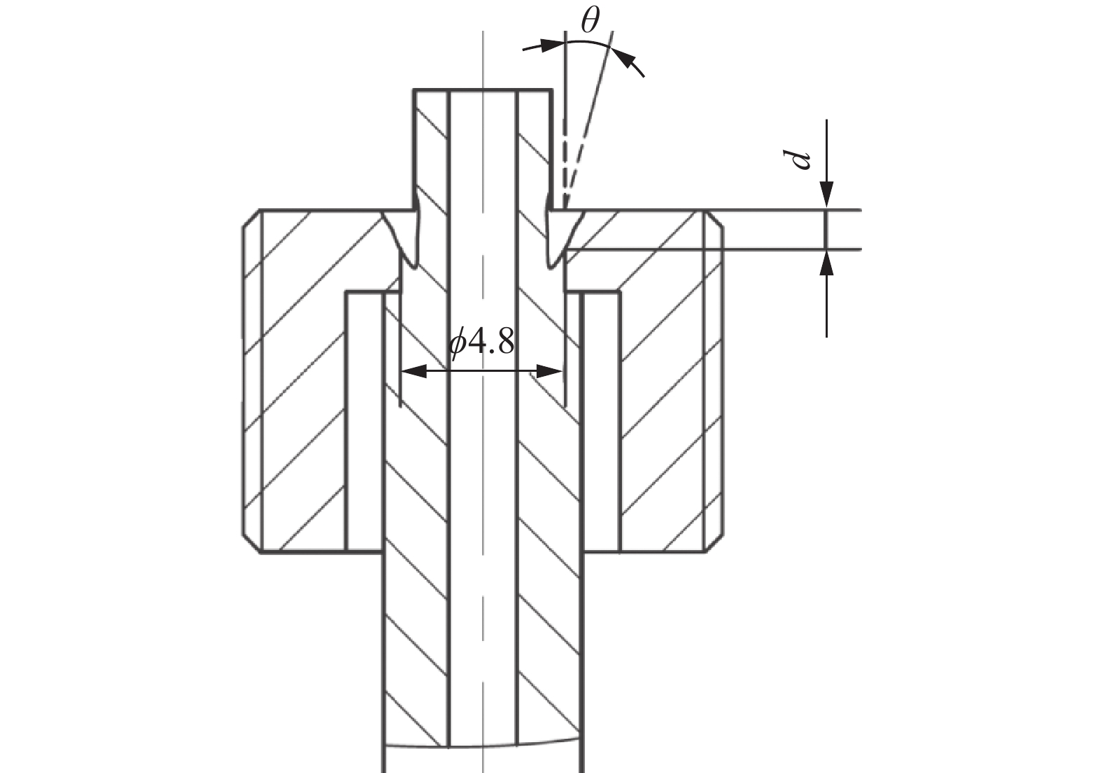
图 2 电子束插接焊接头结构示意图(mm)
Figure 2. Schematic diagram of the electron beam butt welding joint structure
![]()
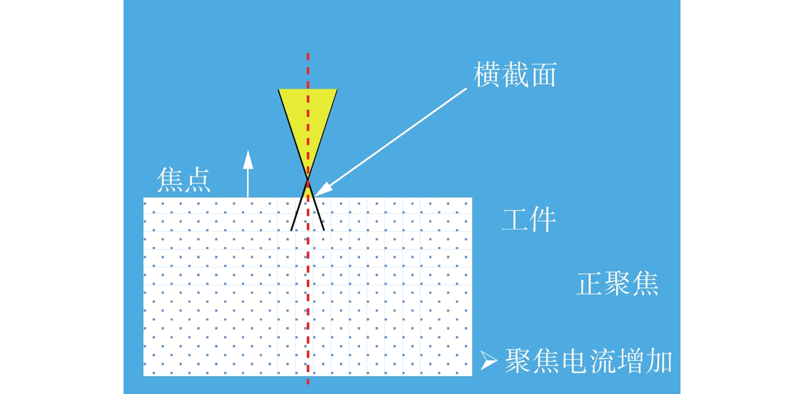
图 4 聚焦电流与电子束焦点位置关系示意图
Figure 4. Schematic diagram of the relationship between focusing current and electron beam focal position
![]()
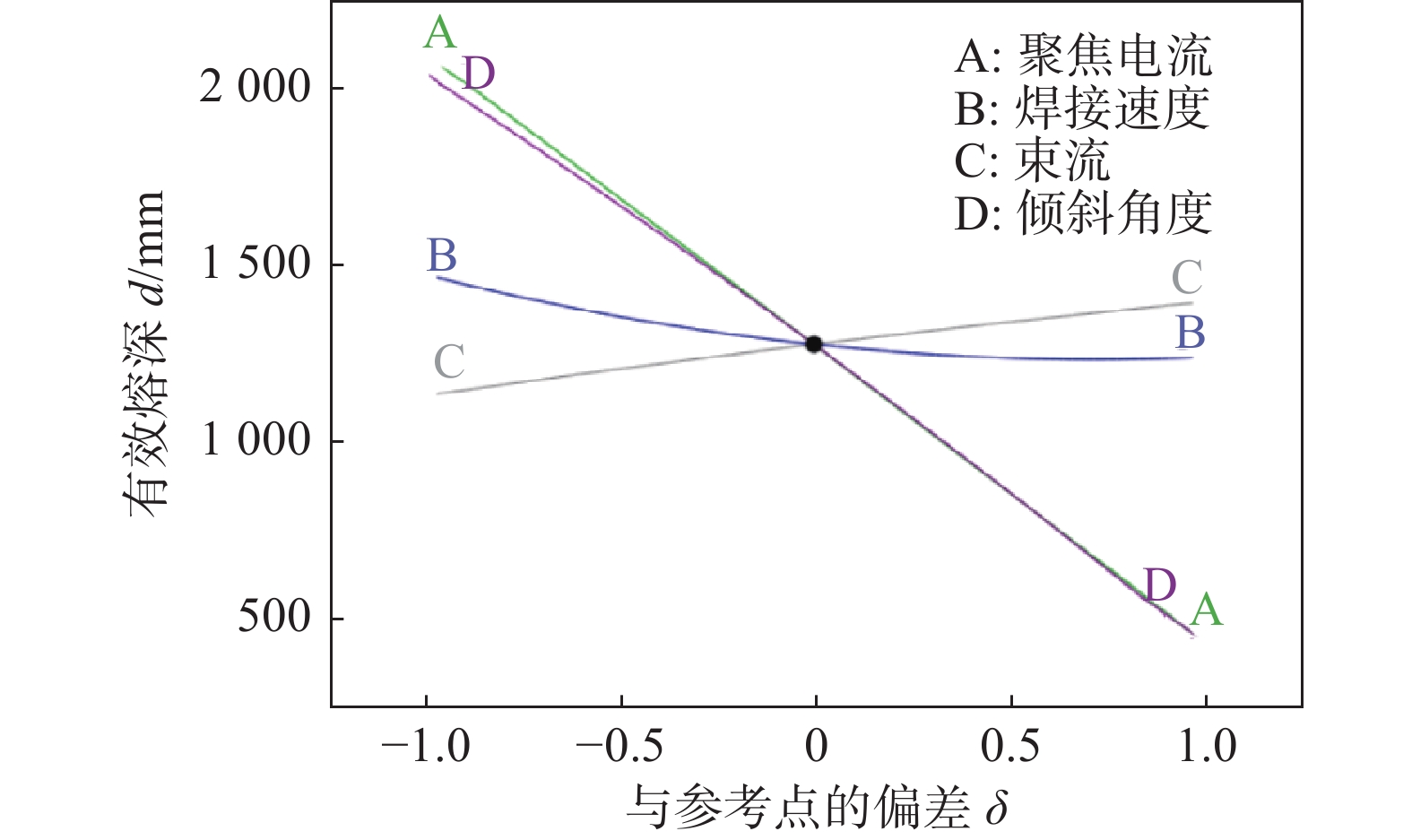
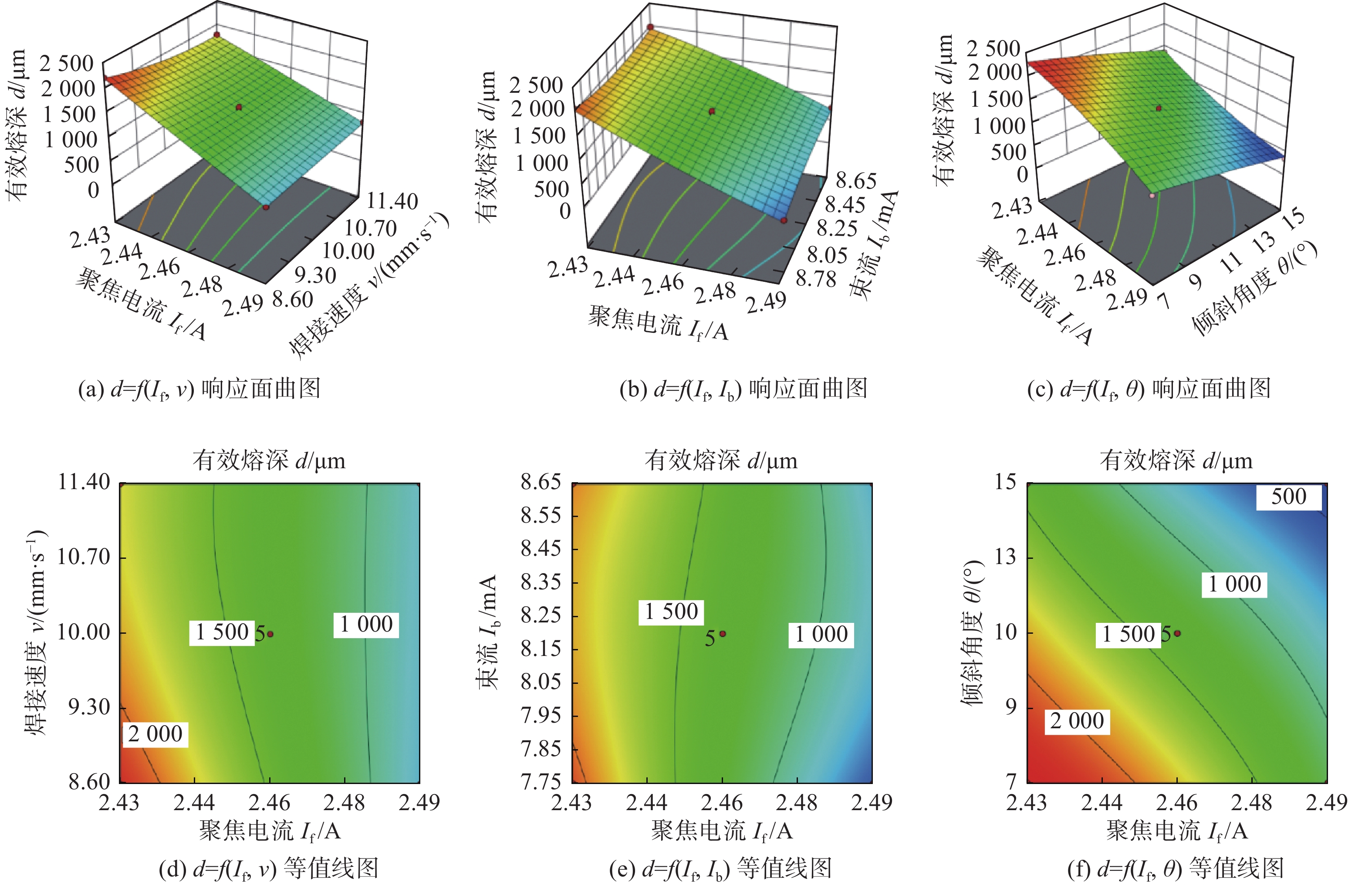
图 5 有效熔深的响应面曲图和等值线图
Figure 5. Response surface 3D graph and contour graph of effective penetration. (a) d = f ( If, v) response surface 3D graph; (b) d = f (If, Ib) response surface 3D graph; (c) d = f ( If, θ ) response surface 3D graph; (d) d = f ( If, v ) contour graph; (e) d = f ( If, Ib) contour graph; (f) d = f ( If, θ ) contour graph
![]()
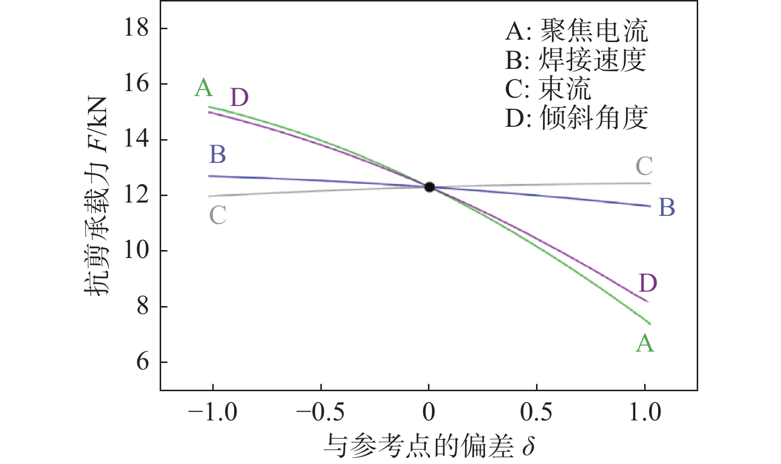
图 6 各交互作用对接头抗剪承载力的影响
Figure 6. Effect of each interaction on the shear capacity of the joints
![]()
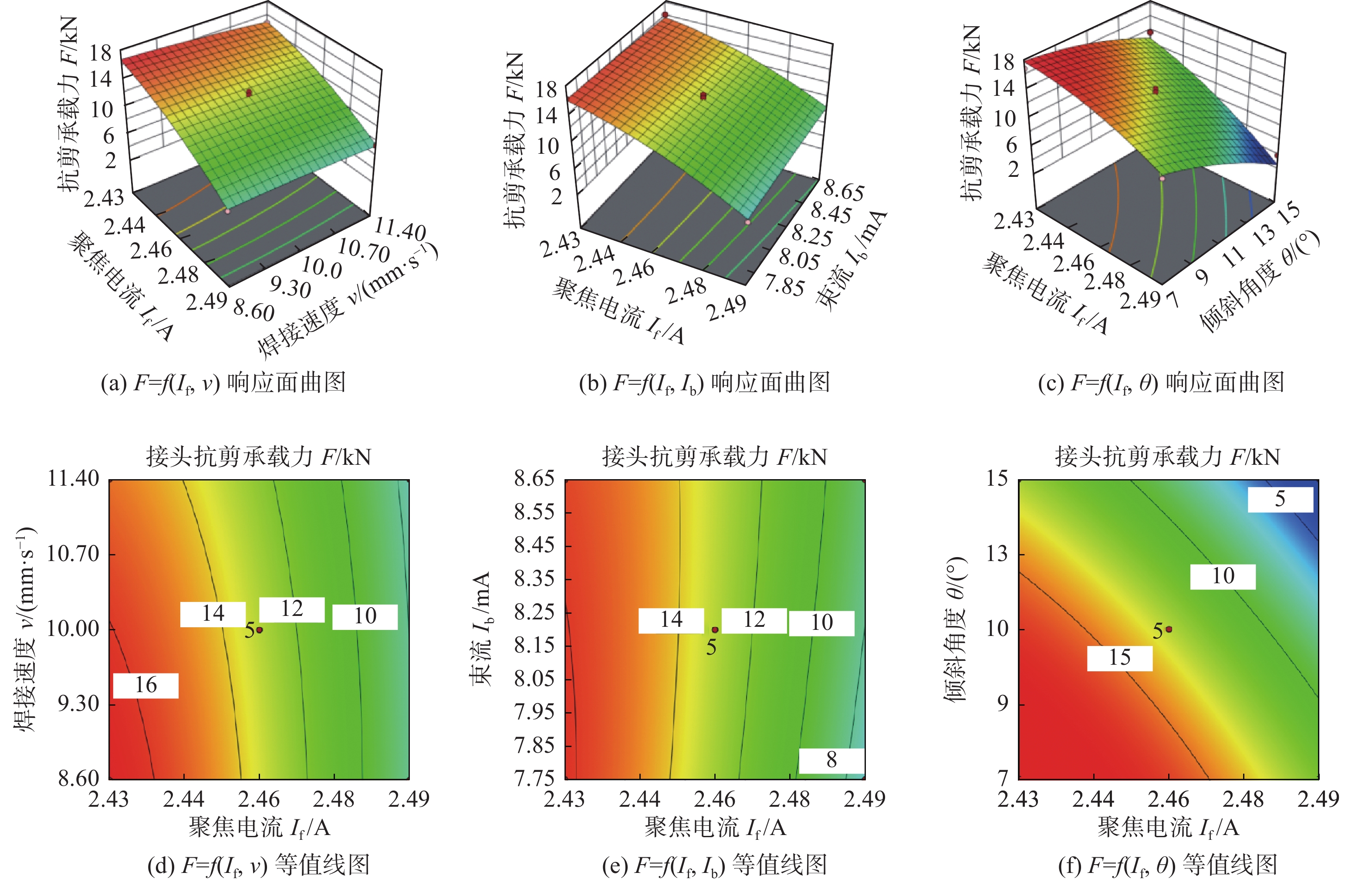
图 7 接头抗剪承载力的响应面曲图和等值线图
Figure 7. Response surface 3D graph and contour graph of of shear capacity of joint. (a) F = f (If, v) response surface 3D graph; (b) F = f (If, Ib) response surface 3D graph; (c) F = f ( If, θ ) response surface 3D graph; (d) F = f ( If, v ) contour graph; (e) F = f ( If, Ib) contour graph; (f) F = f ( If, θ) contour graphe
![]()
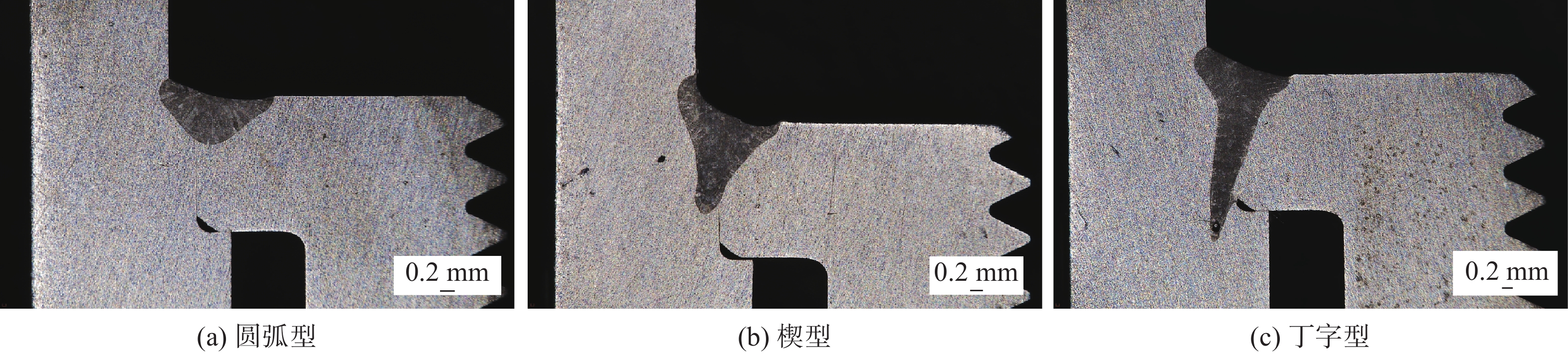
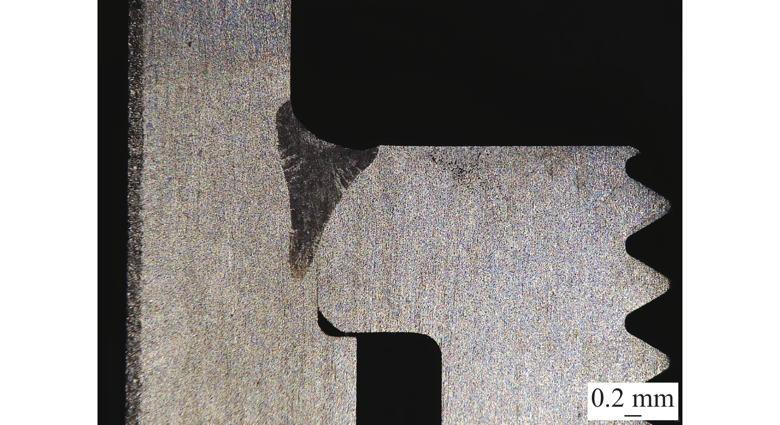
图 8 焊缝截面形貌分类
Figure 8. Classification of the cross-sectional morphology of the weld. (a) arc type; (b) wedge type; (c) T-shaped type
表 1 HR-2抗氢钢的化学成分(质量分数,%)
Table 1 Chemical compositions of HR-2 hydrogen resistant steel
C Si Mn P S Ni Cr Fe ≤0.040 ≤1.00 8.00 ~ 10.00 ≤0.025 ≤0.015 5.50 ~ 8.00 19.00 ~ 21.50 余量  下载: 导出CSV
表 2 工艺参数水平编码及真实值表
Table 2 Process parameter level coding and true value table
水平 聚焦电流
If /A焊接速度
v/(mm·s−1)束流
Ib /mA倾斜角度
θ/(°)1 2.49 11.40 8.65 15 0 2.46 10.00 8.20 11 −1 2.43 8.60 7.75 7
下载: 导出CSV
表 3 试验方案及相对应的响应值
Table 3 Test scheme and corresponding response value
试验序号 聚焦电流If /A 焊接速度v/(mm∙s−1) 束流Ib/mA 倾斜角度θ/(°) 有效熔深d/μm 抗剪承载力F/kN 1 2.49 10.00 8.20 15 360.07 3.856 2 2.43 10.00 8.65 11 1 997.30 16 137 3 2.46 10.00 8.20 11 1 397.18 13.037 4 2.43 10.00 7.75 11 2 117.32 16.352 5 2.43 10.00 8.20 7 2 252.73 16.779 6 2.46 10.00 8.65 15 830.92 8.938 7 2.46 10.00 8.20 11 1 275.58 12.330 8 2.46 11.40 8.20 7 1 840.34 15.907 9 2.46 10.00 7.75 7 1 717.24 16. 096 10 2.46 10.00 8.20 11 1 357.18 13.725 11 2.46 8.60 8.65 11 1 175.61 13.681 12 2.46 11.40 8.20 15 815.54 8.120 13 2.46 10.00 8.65 7 1 975.75 15.935 14 2.49 10.00 8.65 11 787.84 8.388 15 2.49 10.00 7.75 11 575.49 6.710 16 2.49 8.60 8.20 11 775.53 7.844 17 2.43 10.00 8.20 15 1 369.49 13.696 18 2.46 10.00 8.20 11 1 375.64 13.265 19 2.43 11.40 8.20 11 1 796.56 14.908 20 2.46 10.00 8.20 11 1 320.56 13.018 21 2.46 8.60 7.75 11 1 427.96 14.690 22 2.43 8.60 8.20 11 2 203.49 16.368 23 2.49 11.40 8.20 11 827.85 7.564 24 2.46 8.60 8.20 7 2 172.71 16.383 25 2.46 8.60 8.20 15 787.84 8.046 26 2.46 10.00 7.75 15 744.76 7.013 27 2.46 11.40 8.65 11 1 461.81 12.204 28 2.49 10.00 8.20 7 1 089.44 11.404 29 2.46 11.40 7.75 11 1 311.02 11.557
下载: 导出CSV
表 4 有效熔深模型方差分析
Table 4 ANOVA for effective weld penetration reduced cubic model
项目 平方和SS/105 自由度f 均放值MS /105 F值 Prob>F值 模型 80.22 22 3.646 60.48 < 0.000 1 If 11.80 1 11.80 195.74 < 0.000 1 θ 11.21 1 11.21 185.88 < 0.000 1 vIf 0.527 276 4 1 0.527 276 4 8.75 0.025 4 vIb 0.406 304 6 1 0.406 304 6 6.74 0.040 9 IfIb2 0.418 443 5 1 0.418 443 5 6.94 0.038 8 残差 0.361 760 2 6 0.060 293 4 失拟项 0.269 499 2 2 0.134 749 6 5.84 0.065 0 绝对误差 0.092 261 0 4 0.023 065 3 总离差 80.58 28
下载: 导出CSV
表 5 接头抗剪承载力模型方差分析
Table 5 ANOVA for the shear capacity of welded joins reduced quadratic model
项目 平方和SS /107 自由度f 均方值MS /106 F值 Prob > F值 模型 37.13 14 26.52 36.23 < 0.000 1 If 19.58 1 195.8 267.50 < 0.000 1 v 0.379 9 1 3.799 5.19 0.038 9 θ 15.29 1 152.9 208.88 < 0.000 1 θIf 0.498 4 1 4.984 6.81 0.020 6 If2 0.729 9 1 7.299 9.97 0.007 0 θ2 0.404 7 1 4.047 5.53 0.033 9 残差 1.025 14 0.732 0 失拟项 0.923 0 10 0.923 0 3.63 0.113 0 绝对误差 0.101 8 4 0.254 6 总离差 38.15 28
下载: 导出CSV
表 6 响应面法分析优化验证结果
Table 6 Optimization and verification results of response surface analysis method
类别 聚焦电流If /A 焊接速度v/(mm∙s−1) 束流Ib /mA 倾斜角度θ/(°) 有效熔深d/μm 接头抗剪承载力F/kN 试验值 2.46 10.00 8.20 11 1 347.82 13.525 预测值 2.463 10.21 8.12 11.26 1 363.63 13.881 相对误差e(%) 0.12 2.1 −0.98 2.36 1.17 2.63
下载: 导出CSV
-
[1] 丁亚茹, 陈芙蓉, 杨帆, 等. 响应面法分析7075铝合金激光焊接参数对焊接质量的影响规律[J]. 材料导报, 2021, 35(2): 2103 − 2108. Ding Yaru, Chen Furong, Yang Fan, et al. Analyzing the influence of laser welding parameters on the welding quality of 7075 aluminum alloy by response surface methodology[J]. Materials Reports, 2021, 35(2): 2103 − 2108.
[2] Mohammadpour M, Yazdian N, Wang H P, et al. Effect of filler wire composition on performance of Al/Galvanized steel joints by twin spot laser welding-brazing method[J]. Journal of Manufacturing Processes, 2018, 31: 20 − 34.
[3] Kumar C, Das M, Paul C P, et al. Experimental investigation and metallographic characterization of fiber laser beam welding of Ti-6Al-4V alloy using response surface method[J]. Optics and Lasers in Engineering, 2017, 95: 52 − 68. doi: 10.1016/j.optlaseng.2017.03.013
[4] 王洪潇, 史春元, 王春生, 等. 基于响应面法的不锈钢车体激光焊接工艺参数优化[J]. 焊接学报, 2010, 31(10): 69 − 72. Wang Hongxiao, Shi Chunyuan, Wang Chunsheng, et al. Optimization of laser welding parameters of stainless steel vehicle body based on response surface methodology[J]. Transactions of the China Welding Institution, 2010, 31(10): 69 − 72.
[5] Zhang W W, Cong S. Process optimization and performance evaluation on laser beam welding of austenitic/martensitic dissimilar materials[J]. International Journal of Advanced Manufacturing Technology, 2017, 92: 4161 − 4168.
[6] 孔谅, 周洋, 王敏, 等. TA2薄板电弧辅助激光高速焊接的焊缝成形稳定性[J]. 机械工程学报, 2021, 57(10): 137 − 147. Kong Liang, Zhou Yang, Wang Min, et al. Robustness of weld appearance on high-speed arc-assisted laser welding process on titanium sheet[J]. Journal of Mechanical Engineering, 2021, 57(10): 137 − 147.
[7] 范文学, 陈芙蓉. 基于响应面法7A52高强铝合金FSW接头抗拉强度预测及优化[J]. 焊接学报, 2021, 42(9): 55 − 60. Fan Wenxue, Chen Furong. Prediction and optimization of tensile strength of 7A52 aluminum alloy friction stir welding joints based on response surface methodology[J]. Transactions of the China Welding Institution, 2021, 42(9): 55 − 60.
[8] Acherjee B, Misra D, Bose D, et al. Prediction of weld strength and seam width for laser transmission welding of thermoplastic using response surface methodology[J]. Optics & Laser Technology, 2009, 41(8): 956 − 967.
[9] 张明敏, 胡玥, 吴家云, 等. 电子束焊接参数对高温合金小熔深焊缝形貌的影响[J]. 热加工工艺, 2017, 46(1): 233 − 235. Zhang Mingmin, Hu Yue, Wu Jiayun, et al. Effect of electron beam welding parameters on little penetration depth weld shape of high temperature alloys[J]. Hot Working Technology, 2017, 46(1): 233 − 235.
[10] 孙家豪, 张超勇, 吴剑钊, 等. 基于神经网络的316L不锈钢激光焊焊缝形貌预测[J]. 焊接学报, 2021, 42(12): 40 − 47. Sun Jiahao, Zhang Chaoyong, Wu Jianzhao, et al. Prediction of weld profile of 316L stainless steel based on generalized regression neural network[J]. Transactions of the China Welding Institution, 2021, 42(12): 40 − 47.


计量
- 文章访问数: 232
- HTML全文浏览量: 43
- PDF下载量: 39
