
Microstructure and mechanical properties of CuCrZr /316LN laser welding joints on HEPS thin wall vacuum box
-
摘要: 对Inconel625与316LN异种材料合金管进行激光对焊试验,分析各组试样的接头形貌、微观组织、化学成分以及力学性能. 试验结果表明,在1 100 ~ 1 300 W的激光功率、 + 20 mm的离焦量、870 mm/min的焊速以及20 L/min的99.9%Ar气保护时焊缝成形良好,实现Inconel625&316LN薄壁合金管的全位置焊接,焊缝内部缺陷较少. Inconel625&316LN焊缝与母材连接界面元素过渡明显,由于Fe, Ni互溶,在焊缝内部主要由原子比接近1∶1的Fe, Ni固溶体组成;Inconel625&316LN管激光焊接接头抗拉强度较高,由于焊缝内Fe, Ni固溶体分布均匀,镍与钢内Fe, Ni元素互溶形成的固溶体分布较为均匀,使焊缝强度较高,且不低于母材强度,拉伸试验时在拉力作用下不会优先开裂. 随着热输入增加,焊缝内晶体尺寸逐渐增加,焊缝屈服强度逐渐降低,断裂形式以母材韧性断裂为主.Abstract: The laser butt welding experiments of Inconel625 and 316LN dissimilar material alloy tubes were carried out, and the joint morphology, microstructure, chemical composition and mechanical properties of each sample were analyzed. The experimental results show that the weld is in good shape under the laser power of 1 100 to 1 300 W, the defocus of + 20 mm and the welding speed of 870 mm/min and 20 L/min 99.9%Ar gas protection, and the all-position welding of Inconel625&316LN thin-walled alloy pipe is realized with less internal defects. The transition of interface elements between Inconel625&316LN weld and base metal is obvious. Due to the mutual solubility of Fe and Ni, it is mainly composed of Fe and Ni solid solution with atomic ratio close to 1∶1 in the weld. The tensile strength of the laser welded joint of Inconel625&316LN pipe is higher. Due to the uniform distribution of Fe and Ni solid solution in the weld and the solid solution formed by the mutual dissolution of Fe and Ni elements in nickel and steel, the weld strength is higher, and it is not lower than that of the base metal, and it will not give priority to cracking under tensile test. With the increase of heat input, the crystal size in the weld gradually increases, the yield strength of the weld decreases gradually, and the fracture form is mainly the ductile fracture of the base metal.
-
Keywords:
- Inconel625 /
- 316LN /
- dissimilar material alloy tube /
- laser welding /
- interface microstructure /
- joint properties
-
0. 序言
在熔焊中,焊缝微观组织受温度场和热影响区晶粒结构的影响. 在焊接热源高温作用下形成的焊缝与热影响区中的微观组织形貌将影响焊接结构的性能和质量[1]. 因此,微观组织的控制是保证焊接接头力学性能的重要因素. 由于焊接是一个高温、瞬时、动态的复杂过程,采用试验法研究焊接接头组织的演变过程具有一定的限制. 随着计算机技术和材料科学的发展,通过数值模拟技术已经能够再现焊接熔池枝晶演变和热影响区晶粒长大的动态过程[2-7].
Pavlyk等人[3]首次利用有限差分-元胞自动机(FD-CA)模型对惰性气体钨极氩弧焊定向凝固过程中具有相同取向的枝晶生长进行了预测. Zhan等人[4]建立FD-CA模型对焊接熔池中的柱状树枝晶和等轴树枝晶进行了模拟,并提出了“对角线模拟角度”方法实现了具有不同结晶学主轴的柱状树枝晶间的竞争生长. Han等人[5]模拟了焊接熔池内不同区域的枝晶竞争生长过程,并研究了基体晶粒尺寸对柱状晶形貌的影响. 张敏等人[6-7]采用熔池凝固模型实现了焊缝横截面上的枝晶生长模拟. 宋奎晶[8]基于CA模型,并提出粗网格划分方法和相似原理实现了钛合金焊接热影响区晶粒长大的多尺度模拟.
目前的焊接接头微观组织模拟主要集中在焊接熔池枝晶生长或者热影响区晶粒长大,将二者同时考虑的模拟较少. 鉴于此,针对镍基合金TIG焊接过程,建立了枝晶生长模型与晶粒长大模型来模拟焊接温度场作用下的焊接接头微观组织演变过程.
1. 模型建立
1.1 凝固模型
焊接熔池凝固过程主要包括枝晶形核和枝晶生长. 熔池内的晶核数量采用Rappaz等人[9]提出的连续形核模型确定,单位时间步长内,形核密度n(ΔT)可表示为
$$ \begin{split} & n(\Delta T) = \frac{{{n_{\max }}}}{{\sqrt {2{\text π} } \Delta {T_{\text{σ}} }}}\\ & \int_{\Delta T}^{\Delta T + \delta (\Delta T')} {\exp \left[ { - \frac{1}{2}{{(\frac{{\Delta T' - \Delta {T_{\rm{N}}}}}{{\Delta {T_{\text{σ}} }}})}^2}} \right]} {\rm{d}}(\Delta {{T}}') \end{split} $$ (1) 式中:nmax为最大异质形核衬底密度;ΔTσ为标准曲率过冷度;ΔT ′为平均形核过冷度;ΔTN为最大形核过冷度;δ(ΔT ′)为单位时间步长过冷度的变化量. 式(1)可用于描述熔池边缘与中心的非均匀形核.
晶核形成后,开始进入生长阶段. 考虑成分过冷和曲率过冷,固/液界面处液相的溶质浓度可表示为
$$ C_{\rm{L}}^* = {C_0} - \frac{1}{{{m_{\rm{L}}}}}({T_{\rm{L}}} - T - \Gamma \kappa f(\varphi ,\theta )) $$ (2) 式中:mL,TL,Γ为常数;T为局部温度;κ为界面曲率;f(φ,θ)为各项异性函数[10].
模型中假设固/液界面存在局部平衡,通过式(3)进行溶质分配.
$$ C_{\rm{S}}^* = kC_{\rm{L}}^* $$ (3) 式中:k为溶质分配系数;
$C_{\rm{S}}^*$ 和$C_{\rm{L}}^*$ 分别是固/液界面两侧固相和液相中的溶质浓度.固/液界面生长态元胞中的液相溶质浓度为
$$ {C_{\rm{L}}} = C_{\rm{L}}^* - \frac{1}{2}(1 - {f_{\rm{S}}})\Delta x{G_{\rm{L}}} $$ (4) 式中:fS为固相分数[10];Δx为元胞尺寸;GL为液相溶质浓度梯度.
浓度梯度的存在使溶质发生扩散,液相和固相中溶质扩散控制方程为
$$ \frac{{\partial {C_{\rm{L}}}}}{{\partial {\rm{t}}}} = \frac{\partial }{{\partial x}}\left[{D_{\rm{L}}}\frac{{\partial {C_{\rm{L}}}}}{{\partial x}}\right] + \frac{\partial }{{\partial y}}\left[{D_{\rm{L}}}\frac{{\partial {C_{\rm{L}}}}}{{\partial y}}\right] $$ (5) $$ \frac{{\partial {C_{\rm{D}}}}}{{\partial {\rm{t}}}} = \frac{\partial }{{\partial x}}\left[ {{D_{\rm{D}}}\frac{{\partial {C_{\rm{D}}}}}{{\partial x}}} \right] + \frac{\partial }{{\partial y}}\left[ {{D_{\rm{D}}}\frac{{\partial {C_{\rm{D}}}}}{{\partial y}}} \right] $$ (6) 式中:CS为固相中的溶质浓度;CL为液相中的溶质浓度;DS为固相中的溶质扩散系数;DL为液相中的溶质扩散系数.
1.2 热影响区晶粒长大模型
热影响区晶粒长大是通过晶界迁移实现的,通常晶界迁移速度可通过晶界迁移率M和晶界迁移驱动力F [11]计算.
$$ v = MF $$ (7) 考虑到相邻晶粒的位向差,晶界迁移率M可表示为
$$ M = \left\{ {\begin{aligned} & {{M_0}{{\left(\frac{\theta }{{{\theta _{\rm{m}}}}}\right)}^5}},\quad{\theta < {\theta _{\rm{m}}}}\\ & {{M_0} = \frac{{{A_2}{n_1}{v_1}V_{\rm{m}}^2}}{{{N_{\rm{a}}}RT}}\exp \left( { - \frac{{\Delta {G_{\rm{A}}}}}{{RT}}} \right)},\quad{\theta > {\theta _{\rm{m}}}} \end{aligned}} \right. $$ (8) 式中:A2为晶粒接纳原子的概率;n1为单位面积上处于有利跳跃位置的原子数;v1为原子跳跃频率;Vm为原子摩尔体积;Na为阿伏伽德罗常数;R为气体常量;ΔGA为激活能;θ为晶粒的取向差,θm取15°.
晶界迁移驱动力可通过晶界曲率表示为
$$ F = \gamma \cdot \kappa $$ (9) 式中:γ为单位面积的晶界能;κ为晶界曲率. 其中γ服从Read-Shockley公式,κ可通过等效模型法计算得到[12].
中心元胞状态转变为邻居元胞状态的概率P为
$$ P = \left\{ {\begin{split} & 0,\quad{{G_{\rm{T,i}}} < \Delta {G_{\rm{A}}} - \sum {\Delta {G_{\rm{i}}}} }\\ & {\frac{{{M_{\rm{i}}}{{F_{\rm{i}}}}}}{{{M_{\max }}{F_{\max }}}}},\;\;{{G_{\rm{T,i}}} > \Delta {G_{\rm{A}}} - \sum {\Delta {G_{\rm{i}}}} } \end{split}} \right. $$ (10) 式中:GT,i为元胞内能;
$\sum {\Delta {G_{\rm{i}}}}$ 为元胞转变前后的自由能差. 给元胞赋予随机数r (0 ≤ r ≤ 1),若P > r,则元胞状态发生转变.1.3 初始条件
温度场模型中采用的构件尺寸为100 mm × 50 mm × 2 mm,材料为镍基合金GH3039,计算所用的热物性参数详见文献[13]. 焊接方式为TIG焊,焊接电流为75 A,电弧电压为10 V,焊接速度为2 mm/s. 针对薄板TIG焊,选用高斯热源模型,通过商业有限元软件计算获得焊接温度场,并将节点热循环曲线通过双线性插值计算得到元胞自动机模型中温度条件.
CA模型中选择焊缝横截面上的微观组织演变过程作为研究对象,选取的计算域尺寸为1 mm × 2 mm. 母材晶粒结构通过等轴晶形核和生长获得,其中母材晶粒尺寸设为32 μm(该值由试验测量得到). 晶粒取向总数设为48,其值在1 ~ 48之间随机给出,晶粒的择优生长取向随机赋予−45° ~ 45°之间的角度. 热影响区晶粒长大模型中的元胞尺寸设为4 μm,凝固模型中的元胞尺寸设为2 μm,时间步长设为0.000 1 s. 凝固枝晶生长模型中的初始参数如表1所示[14].
表 1 微观组织模拟参数Table 1. Parameters used in the Microscopic Simulation液相线温度TL/K 液相线斜率mL 溶质分配系数k 液相扩散系数DL/(m2·s−1) 固相扩散系数DS/(m2·s−1) Gibbs Thomson系数Γ/(K·m) 初始溶质浓度C0(%) 1 640 −2.1 0.714 2.0 × 10⁻⁹ 3.7 × 10⁻¹² 2.0 × 10⁻⁷ 20 2. 结果与讨论
2.1 温度场模拟结果
图1为宏观有限元模型计算得到的焊接过程某一时刻构件上表面、焊缝横截面及微观组织计算区域内插值后的温度场分布情况. 为了将熔池部分区分出来,将高于熔池边界温度的区域用灰色表示,熔池边界温度为1 367 ℃. 由构件上表面温度场云图可以看出熔池呈现椭圆形,熔池前方的等温线较为密集,温度梯度大,熔池后端的等温线稀疏,温度梯度较小. 由图1b中的温度分布可以看出不同区域的温度分布和最大温度梯度方向是不一致的. 选取图中黑色线框中的区域作为微观组织的计算范围,将该区域中节点的热循环曲线进行双线性插值可以得到任意时刻任一元胞的温度值,某一时间步微观尺度上的温度场分布如图1c所示.
![]() 图 1 焊接过程温度场云图Figure 1. Temperature field during the welding process. (a) temperature field on the upper surface of the workpiece; (b) temperature field of the weld cross-section; (c) temperature field in the calculation domain obtained by interpolation
图 1 焊接过程温度场云图Figure 1. Temperature field during the welding process. (a) temperature field on the upper surface of the workpiece; (b) temperature field of the weld cross-section; (c) temperature field in the calculation domain obtained by interpolation2.2 焊接接头微观组织模拟结果
焊接接头微观组织模拟结果如图2所示. 图2a表示焊接构件横截面上的母材晶粒分布情况. 随着热源的靠近,母材熔化形成熔池,如图2b中深色区域所示. 熔池附近的晶粒在热作用下开始长大,距离熔合线越近,晶粒生长越明显. 当晶粒长大到一定程度后将基本不再变化,如图2c所示.晶粒生长过程主要是通过大晶粒吞噬小晶粒完成的. 随着热源的离开,构件的整体温度逐渐下降,熔池开始凝固. 由于熔池边缘散热较快且易于形核,在此处率先形成的晶核开始以柱状树枝晶的形式向熔池中心生长. 图中用不同灰度表示具有不同择优生长取向的晶粒,这些具有不同取向的枝晶在生长过程中逐渐靠近并发生竞争生长,择优取向与最大温度梯度方向相近的枝晶更易于生长,竞争优势较弱的枝晶在生长过程逐渐被挤压,直至停止生长,如图2d所示.由同一母材晶粒联生结晶形成的枝晶簇具有相同的择优生长方向,其凝固后在焊缝中表现为完整的柱状晶粒. 当熔池中的最大过冷度增大到足以形成新的晶核时,大量具有随机取向的晶核在柱状晶前沿形成并阻碍柱状晶的生长,因此在凝固后焊缝中心形成了连续的等轴晶区,如图2e所示.图2f为联生结晶与柱状晶向等轴晶转变过程. 熔池内的柱状晶结构和宽度主要与热影响区中的晶粒取向和尺寸有关,热影响区的晶粒粗化现象越明显,熔合线附近的母材晶粒数量越少,由同一晶粒联生结晶形成的柱状树枝晶数量增多,使得焊缝中的柱状晶变得粗大.
![]() 图 2 不同时刻焊接接头微观组织形貌Figure 2. Microstructure of welded joint at different times. (a) predicted grain distribution of the base metal; (b) 5 000 CAs; (c) 11 000 CAs; (d) 21 000 CAs; (e) 32 000 CAs; (f) epitaxial solidification and the columnar to equiaxed transition
图 2 不同时刻焊接接头微观组织形貌Figure 2. Microstructure of welded joint at different times. (a) predicted grain distribution of the base metal; (b) 5 000 CAs; (c) 11 000 CAs; (d) 21 000 CAs; (e) 32 000 CAs; (f) epitaxial solidification and the columnar to equiaxed transition为了验证模拟结果的可靠性,选取2 mm厚的GH3039镍基合金进行TIG焊接试验,选用的焊丝牌号为HGH3039. 通过金相试验获得的焊接接头微观组织如图3所示.由图3a可以看出,熔池内部主要的枝晶形态为柱状树枝晶和等轴树枝晶.柱状树枝晶前沿为大量的等轴晶组织. 由图3b可以看到热影响区的晶粒与母材相比发生了明显的粗化,通过截线法测量得到该区域的晶粒平均尺寸约为132 μm. 同理可得模拟的热影响区晶粒平均尺寸约为129 μm,模拟结果与试验结果吻合较好,说明了该模型可用于焊接熔池及热影响区的微观组织演变过程模拟.
![]() 图 3 焊接接头微观组织分布Figure 3. Micrographs of welded joint. (a) dendrite morphology of the molten pool; (b) grain distribution of the heat-affected zone
图 3 焊接接头微观组织分布Figure 3. Micrographs of welded joint. (a) dendrite morphology of the molten pool; (b) grain distribution of the heat-affected zone3. 结论
(1)所建立的热影响区晶粒长大模型能够较好的模拟热作用下的晶粒粗化过程.
(2)所建立的枝晶生长模型能够对焊接熔池凝固过程中半熔化母材边缘的联生结晶,不同枝晶间的竞争生长和熔池中心的等轴晶生长过程进行模拟,可以完整的再现焊接接头微观组织的动态演变过程.
(3)模拟结果能够较好的体现焊接热影响区晶粒尺寸与焊缝柱状晶宽度之间的关系.
(4)模拟得到熔池微观组织和热影响区晶粒分布与试验结果吻合较好,由此验证了模型的可靠性.
-
![]()
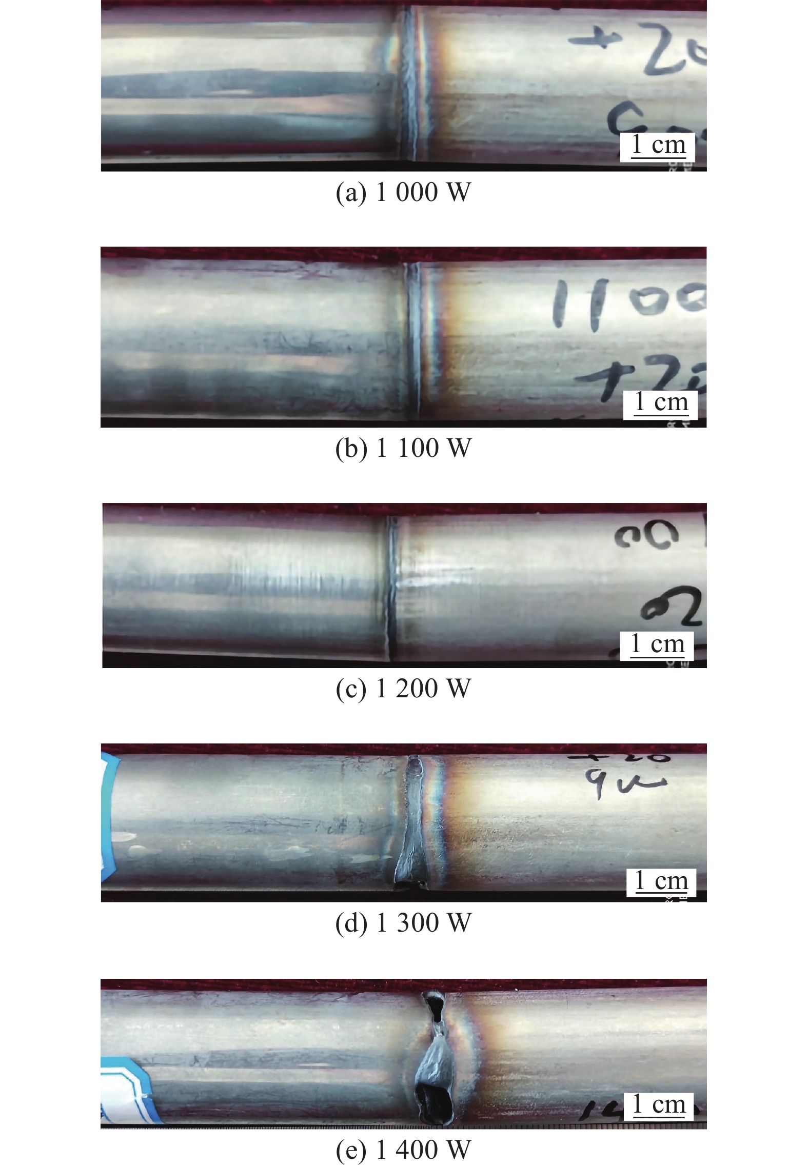
图 1 Inconel625&316LN异种管件焊缝成形
Figure 1. Weld forming of Inconel625&316LN. (a) 1 000 W; (b) 1 100 W; (c) 1 200 W; (d) 1 300 W; (e) 1 400 W
![]()
图 2 Inconel625&316LN管件焊缝横截面形貌
Figure 2. Weld cross section morphology of Inconel625&316LN. (a) 1 000 W; (b) 1 100 W; (c) 1 200 W; (d) 1 300 W; (e) 1 400 W
![]()
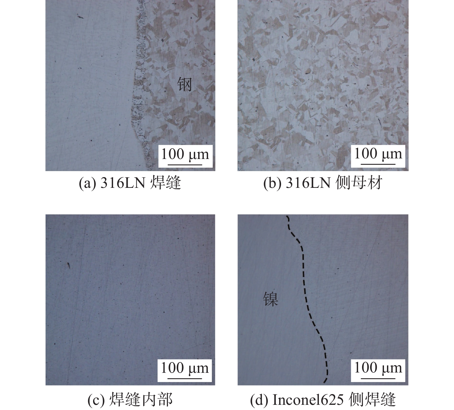
图 3 1 200 W激光功率下Inconel625&316LN焊缝微观组织
Figure 3. Weld microstructure of Inconel625&316LN at 1 200 W laser power. (a) meld line of 316LN side; (b) metallographic morphology of base metal of 316LN side; (c) weld center; (d) meld line of Inconel625 side
![]()
图 4 Inconel625&316LN焊缝形貌以及元素分布
Figure 4. Weld morphology and element distribution of Inconel625&316LN joint. (a) interface line scanning direction of 316LN side joint weld; (b) line scan analysis results of 316LN side joint weld; (c) interface line scanning direction of Inconel625 side joint weld; (b) line scan analysis results of Inconel625 side joint weld
![]()
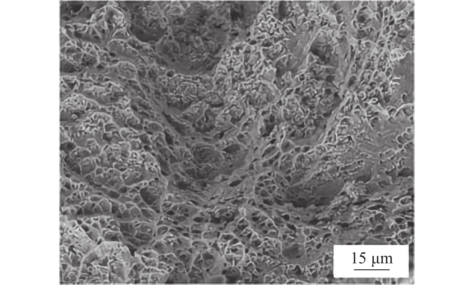
图 8 Inconel625&316LN管激光焊接接头拉伸断口形貌
Figure 8. SEM morphology of tensile fracture of laser welded Inconel625&316LN joint
表 1 Inconel625化学成分(质量分数,%)
Table 1 Chemical compositions of Inconel625
C Si Mn Al Ti Ni Cr Fe Co Nb 0.01 0.50 0.50 0.40 0.40 58 ~ 68 20 ~ 30 5.0 1.0 3.1 ~ 4.1  下载: 导出CSV
表 2 316LN化学成分(质量分数,%)
Table 2 Chemical compositions of 316LN
C Si Mn P S Ni Cr Mo N C + N Fe ≤0.03 ≤0.75 ≤2.00 ≤0.03 ≤0.02 10.00 ~ 14.00 16.00 ~ 18.50 0.12 ~ 0.17 0.12 ~ 0.17 ≤0.15 余量
下载: 导出CSV
表 3 Inconel625&316LN能谱分析结果(原子分数,%)
Table 3 Energy spectrum analysis of Inconel625&316LN
分析点 Fe Ni Cr Mo Nb P1 35.29 36.61 22.02 1.82 4.26 P2 40.93 34.75 19.55 1.17 3.60 P3 38.01 32.49 21.00 1.40 7.10
下载: 导出CSV
-
[1] Jiao Y, Xu G. DA optimization experiences in the HEPS lattice design[J]. Journal of Physics:Conference Series, 2018, 1067(3): 1367 − 1370.
[2] 姜晓明, 王九庆, 秦庆, 等. 中国高能同步辐射光源及其验证装置工程[J]. 中国科学, 2014, 44(10): 1075 − 1094. Jiang Xiaoming, Wang Jiuqing, Qin Qing, et al. Chinese high energy photon source and the test facility[J]. Science China, 2014, 44(10): 1075 − 1094.
[3] Pravin K N, Siva S N, Sreedhar G. High cycle fatigue behaviour of Inconel 625 weld overlay on AISI 316L plate[J]. Surface & Coatings Technology, 2021, 415: 127 − 138.
[4] Vemanaboina H, Kotthinti N K, Chittemsetty V. Multipass dissimilar joints for SS316L to Inconel625 using gas tungsten arc welding[J]. Materials Today:Proceedings, 2021, 46: 567 − 571. doi: 10.1016/j.matpr.2020.11.287
[5] Duan M, Han L, Sun W, et al. Development and performance test of CuCrZr/316L explosive welding plate for EAST Lower divertor heat sink[J]. Fusion Engineering and Design, 2020, 160: 1 − 6.
[6] Zhao S X, Wang M J, Kou S Z, et al. Microstruc- tures and mechanical properties of electron beam welded CuCrZr/Inconel/316L tube-to-tube junctions for WEST project[J]. Fusion Engineering and Design, 2020, 151: 1 − 8.
[7] Wang M J, Zhao S X, Wang W J, et al. Preliminary results of CuCrZr/316L tube-to-tube junctions fabricated with rotary friction welding[J]. Fusion Engineering and Design, 2019, 148: 1 − 7.
[8] Chai M Y, Zhang J, Zhang Z X, et al. Acoustic emission studies for characterization of fatigue crack growth in 316LN stainless steel and welds[J]. Applied Acoustics, 2017, 126: 101 − 113. doi: 10.1016/j.apacoust.2017.05.014
[9] 马锐, 吴继红, 施未来, 等. 316L(N)/CuCrZr中空结构件爆炸焊接工艺[J]. 解放军理工大学学报(自然科学版), 2016, 17(2): 180 − 186. Ma Rui, Wu Jihong, Shi Weilai, et al. Explosive welding process for manufacturing 316L(N)/CuCrZr hollow structural member[J]. Journal of PLA University of Science and Technology (Natural Science Edition), 2016, 17(2): 180 − 186.
[10] Chai M Y, Duan Q, Zhang Z X. Acoustic emission response of 316LN welded joint during intergranular corrosion[J]. Materials Science Forum, 2014, 809: 401 − 405.
[11] Lalvani H, Mandal P. Cold forming of Al-5251 and Al-6082 tailored welded blanks manufactured by laser and electron beam welding[J]. Journal of Manufacturing Processes, 2021, 68: 1615 − 1636. doi: 10.1016/j.jmapro.2021.06.070
[12] Li N, Wang T, Jiang S, et al. Microstructure evolution and strengthening mechanism of electron beam welded TiBw/Ti6Al4V composite joint[J]. Materials Characterization, 2021, 178: 1 − 10.
[13] 刘莹莹, 李洁洁, 张乐. 电子束焊接工艺参数对Ti2AlNb/TC18接头组织与性能的影响[J]. 中国有色金属学报, 2021, 31(3): 699 − 706. doi: 10.11817/j.ysxb.1004.0609.2021-35973 Liu Yingying, Li Jiejie, Zhang Le. Effects of electron beam welding processing parameters on microstructure and properties of Ti2AlNb/TC18 joint[J]. The Chinese Journal of Nonferrous Metals, 2021, 31(3): 699 − 706. doi: 10.11817/j.ysxb.1004.0609.2021-35973
[14] Fan X, Shen X, Zhang Y, et al. Microstructure and mechanical properties of similar and dissimilar joints of RAFM and 316L by electron beam welding[J]. Fusion Engineering and Design, 2021, 162: 1 − 6.
[15] Niu H, Jiang H C, Zhao M J, et al. Effect of interlayer addition on microstructure and mechanical properties of NiTi/stainless steel joint by electron beam welding[J]. Journal of Materials Science & Technology, 2021, 61: 16 − 24.
[16] 邓彩艳, 尹庭辉, 龚宝明. TC11钛合金电子束焊接接头超高周疲劳性能[J]. 焊接学报, 2018, 39(4): 23 − 26. doi: 10.12073/j.hjxb.2018390088 Deng Caiyan, Yin Tinghui, Gong Baoming. Properties of very-high-cycle fatigue of TC11 titanium alloy EBW welded joints[J]. Transactions of the China Welding Institution, 2018, 39(4): 23 − 26. doi: 10.12073/j.hjxb.2018390088
[17] Wang L W, Chen S J, Xiao J, et al. Droplet-targeting laser hybrid indirect arc for additive manufacturing technology-A preliminary study[J]. China Welding, 2020, 29(1): 50 − 55.
[18] Tian D Y, Yan T Y, Gao Q Y, et al. Thermal cycle and its influence on the microstructure of laser welded butt joint of 8 mm thick Ti-6Al-4V alloy[J]. China Welding, 2019, 28(3): 61 − 66.
[19] 唐仁政, 田荣璋. 二元合金相图及中间相晶体结构[M]. 长沙: 中南大学出版社, 2009. Tang Renzheng, Tian Rongzhang. Binary alloy phase diagrams and crystal structure of intermediate phase[M]. Changsha: Central South University Press, 2009.
-
期刊类型引用(4)
1. 陈俊刚. 低合金高强度结构钢焊接结晶裂纹预防措施探析. 中国机械. 2024(08): 57-60 .  百度学术
百度学术
2. 王诗洋,刘士伟,侯星宇,孙元,曹楠,石万鹏. 焊丝成分对镍基高温合金TIG焊焊接性的影响. 焊接学报. 2023(03): 31-36+60+130-131 . 本站查看
3. 魏超,郭枭,韩维超,姜英龙,吕晓春,徐理想. 基于原位拉伸的ERNiCrFe-13焊丝熔敷金属断裂机制分析. 焊接学报. 2023(09): 74-80+133 . 本站查看
4. 郭枭,谷宇,韩莹,徐锴,王岩,姜英龙. Inconel 625合金堆焊金属开裂机理研究. 焊接学报. 2023(11): 117-123+135-136 . 本站查看
其他类型引用(2)


计量
- 文章访问数: 225
- HTML全文浏览量: 53
- PDF下载量: 21
- 被引次数: 6
