
Effect of liquid phase separation on microstructure and properties of T2 copper/316L stainless steel joint
-
摘要: 采用钨极氩弧焊填充纯铜焊丝进行T2紫铜/316L不锈钢异种金属焊接工艺试验,分析了接头微观组织的形成机制. 结果表明,使用纯铜焊丝时,铁-铜液相分离对铜/钢焊缝组织的形成起主导作用. 以铜为基体的焊缝中分布着大量由铁-铜初次液相分离形成的富铁球,在其内部还分布有标志着铁-铜二次液相分离的富铜相. 富铁球内的析出相在表面能梯度和密度差的作用下,向富铁球中心呈球状聚集. 由于成分和所处区域的冷却速率不同,富铁球呈现不同的形貌. 基于熔池边界凝固理论,分析了接头铜/钢界面未混溶区宏观偏析机制. 填丝焊时,熔池边缘形成非等温边界. 纯铜焊丝制备接头铜/钢界面处液态钢母材的温度高于熔池主体,导致岛状和半未混溶区的形成. 接头的铜侧存在由粗大晶粒和正常尺寸晶粒组成的软化区,拉伸试样均断裂于此,抗拉强度达到铜母材的81.7%.Abstract: Dissimilar T2 copper/316L stainless steel joints without defects were prepared by gas tungsten arc welding with Cu filler wire. Microstructure evolution and mechanical properties the joints were investigated. When Cu filler wire was used, the microstructure of copper/steel weld was largely affected by liquid phase separation between iron and copper. Fe-rich spherulites produced by primary liquid phase separation distributed in Cu-based weld. Inside the Fe-rich spherulites, minority Cu-rich spheres formed by secondary liquid phase separation. During solidification, the internal precipitated phases migrated to the center of Fe-rich spherulites due to the interface energy gradient and density difference. The Fe-rich spherulites presented different morphologies because of the differences in composition and cooling rate. The macro-segregation mechanism of melted unmixed zone near fusion boundary was studied based on solidification theory of fusion-boundary. When copper filler wire was used, non-isothermal pool boundary formed at fusion boundaries. The liquidus temperature of bulk weld pool is lower than that of steel base metal in joint. Resultantly, a bulk molten pool cooler than the melted 316L base metal formed near the solidification front. Subsequently, the melted unmixed BM was carried into the cooler molten pool by the convection and agitation, and solidified quickly into a peninsula and island shape before it fully mixed with the bulk weld pool. A softened zone existed in the copper sheet, which consisted of zones with different grain sizes. All tensile specimens fractured at HAZ on the copper side with a ductile fracture mode, and the maximum strength reached 81.7% that of Cu base metal.
-
0. 序言
铜/钢异质金属焊接可以将铜良好的导电、导热性能与不锈钢的高耐蚀性、高强度的特点相结合,有利于更好发挥两种金属的优势,已经在很多领域得到应用[1-3]. 铜/钢熔化焊时,熔池冷却过程中发生的铁-铜液相分离,容易造成缺陷[4].
铜/钢熔化焊研究表明[5-7],焊缝的特征组织为枝晶状或球状的泛铁分布在铜基体上,或球状富铜相分布于富铁基体中. 铜/钢焊缝的相组成通常为ε-Cu以及α-Fe/γ-Fe. 由此可见,铁-铜间的液相分离现象对铜/钢焊缝微观组织的形成起主导作用. 熔池冷却过程中,当其过冷度大于临界过冷度时,原本无限互溶的液相进入混溶间隙,发生铁-铜液相分离,形成两个互不相溶的液相[7]. 两液相依照杠杆定律分别形成基体和少数相. 少数相在表面张力作用下形成球体[8],成为基体中的富铁球或富铜球. Chen等人[9]用液相分离理论解释了铜/钢激光焊接头中初次液相分离所形成的富铜球和其内部形成的二次液相分离富铁球,并总结了影响液相分离程度的因素有冷却速度、原子扩散速率以及混溶间隙的形状. 液相分离不但对铜/钢焊缝的组织形成起主导作用,还会影响接头的力学性能. Cheng等人[10]和Chen等人[11]在铜/钢熔焊中发现,由于富铁相与富铜相的杨氏模量不同,在焊接残余应力作用下,富铁相可成为裂纹源,在接头内部形成裂纹. 这意味着焊缝中尽可能少的铁、铜混合有利于得到性能良好的接头. 然而,Meng等人[12]和Guo等人[13]认为,均匀分布的液相分离富铁相对铜基体起到弥散强化作用. 熔池中充分的液相分离产生的大量均匀分布的富铁球阻碍了铜晶粒的生长,有利于形成细小等轴晶.
目前铜/钢熔化焊相关研究仅分析了铁-铜液相分离对接头力学性能的影响,但由液相分离控制的铜/钢焊缝微观组织的形成机理尚未得到深入研究. 采用纯铜焊丝对T2紫铜/316L不锈钢异质金属进行钨极氩弧焊(gas tungsten arc welding,GTAW),重点分析了铁-铜液相分离对铜焊丝制备接头微观组织的影响,并对接头力学性能进行研究.
1. 试验方法
采用GTAW对1 mm厚316L不锈钢和T2紫铜进行对接焊,焊丝选用直径为1.2 mm的纯铜焊丝. 母材和焊丝的化学成分如表1所示. 焊前用240号砂纸去除母材端面上的氧化膜和机械加工痕迹,然后用酒精清洗母材以去除油污. 采用的保护气体为氩气. 具体的焊接工艺参数如表2所示.
表 1 母材和焊丝的化学成分(质量分数, %)Table 1. Chemical compositions of base materials and filler wires材料 Ni Cr Mo Mn Si P S Sn Fe Cu 316L不锈钢 10.56 17.50 2.07 1.06 0.43 $\leqslant $0.03 $\leqslant $0.03 — 余量 0.05 T2紫铜 — — — — $\leqslant $0.03 $\leqslant $0.01 $\leqslant $0.01 — — 余量 Cu焊丝 — — — $\leqslant $0.5 $\leqslant $0.5 — — ≤1.0 — 余量 表 2 焊接工艺参数Table 2. Welding experiment paraments气体流量Q/(L·min−1) 焊接电流
I/A送丝速度
vg/(mm·s−1)行走速度
vw/(mm·s−1)10 130 6 1 2. 试验结果与分析
2.1 宏观形貌
图1为焊缝外观与接头截面的宏观形貌. 由于焊接时采用了直流反接模式,电弧稳定,焊缝周围无飞溅. 焊接参数选取适当,未造成咬边、表面裂纹等缺陷. 从接头的截面形貌可知,焊丝与母材间具有良好的润湿性. 接头内部无铜/钢焊接时常见的气孔、热裂纹、渗透裂纹等缺陷.
![]() 图 1 焊缝及接头的宏观形貌Figure 1. Appearance and cross-section morphology of the weld. (a) top appearance of weld; (b) back appearance of weld; (c) cross-section morphology of weld
图 1 焊缝及接头的宏观形貌Figure 1. Appearance and cross-section morphology of the weld. (a) top appearance of weld; (b) back appearance of weld; (c) cross-section morphology of weld铜/钢界面处形成了虚线所标记的未混溶区(unmixed melted zone, UMZ),该区域在焊接过程中熔化并溶解了过饱和的铜[14]. 在熔池的对流和搅拌作用下,UMZ呈岛状分布在钢/焊缝界面附近,或呈半岛状依附在钢侧界面上.
2.2 微观组织
2.2.1 富铁球
当采用纯铜焊丝焊接铜/钢时,铁-铜间的冶金反应对焊缝组织的形成起主导作用. 图2为焊缝特征组织. 焊缝内的特征组织之一是富铁球,如图2a所示. 根据Fe-Cu二元相图[15]可知,当熔池的过冷度大于过冷度阈值ΔTC(即一定成分下液相线和混溶间隙之间的温差[8])时,无限互溶的液相发生初次液相分离,生成富铁液滴,其在随后的冷却过程中形成富铁球;富铁球还会发生二次液相分离,内部形成富铜液滴,在凝固过程中形成富铜析出相. 富铁球的成分分析结果如表3所示.
![]() 图 2 焊缝特征组织Figure 2. Characteristic microstructure in the weld. (a) Fe-rich spherulite; (b) internal precipitate
图 2 焊缝特征组织Figure 2. Characteristic microstructure in the weld. (a) Fe-rich spherulite; (b) internal precipitate从图2b可以看出,富铁球中析出相的组成并不单一. 根据A点成分和Fe-Cu二元相图可知,A处深灰色相为Fe在ε-Cu中的过饱和固溶体,标志着Fe和Cu间二次液相分离的发生. 然而,这并不是富铁球中发生的唯一反应. 根据B处成分和Fe-Cr-Mo三元相图[16]可以推测B处浅灰色相为Fe-Cr-Mo间形成的金属间化合物(intermetallic compound, IMC)σ相. 由图3析出相元素分布图可知,σ相主要依附或包裹于二次液相分离形成的富Cu球. 图中BEI为背散射电子像(back-scattered electron image). Gao等人[17]也在纯Mo/不锈钢激光焊中检测到σ相,Yang等人[18]通过热力学模拟和动力学模拟证实了316L不锈钢中存在σ相. 虽然σ相在平衡状态下的分解温度约为472 ℃,但由于焊接过程中的冷却速度很快,并且Cr元素对其起稳定作用,故σ相仍能在室温下存在.
表 3 富铁球EPMA定量分析结果Table 3. EPMA quantitative analysis results of Fe-rich spherulite位置 元素含量(原子分数, %) 可能相 Fe Cu Cr Ni Mo A 10.2 80.4 4.2 1.5 3.6 富铁ε-Cu B 48.7 2.0 26.0 2.4 20.9 σ C 66.1 5.6 18.9 3.9 5.4 α-(Fe, Cr) D 2.8 95.1 0.7 1.3 0.0 ε-Cu ![]() 图 3 富铁球内析出相元素分布Figure 3. Elemental distribution of precipitates in Fe-rich spherulite
图 3 富铁球内析出相元素分布Figure 3. Elemental distribution of precipitates in Fe-rich spherulite从富铁球的形貌和C点定量分析结果可知,其外围存在富铁环. 富铁环的形成与球内析出相的运动有关. 在富铁球内部,富铜球和σ相在表面能差的驱动下发生运动. 由温度差引起的表面能差(thermal marangoni migration, VMT)[19]使析出相向富铁球中心运动;由浓度差引起的表面能差(solutal marangoni convection, VMS)[20]使析出相向富铁球表面运动. 理论上,由于析出相与富铁基体的密度差导致的斯托克斯运动(stokes motion)会使富铜球和Fe-Cr-Mo相在富铁球中向下运动. 析出相在基体中的斯托克斯速度VS可由斯托克斯方程衡量[21].
$$\begin{split} &\\ & {V}_{{\rm{S}}}\approx \frac{2\left({\rho }_{{\rm{m}}-}{\rho }_{{\rm{d}}}\right)g{r}^{2}}{3{\eta }_{{\rm{m}}}}\cdot \frac{{\eta }_{{\rm{m}}} + {\eta }_{{\rm{d}}}}{{2\eta }_{{\rm{m}}} + 3{\eta }_{{\rm{d}}}} \end{split} $$ (1) 以在富铁球中析出的富铜球状相为例,
${\rho }_{{\rm{m}}}$ 和${\rho }_{{\rm{d}}}$ 分别为富铁基体和富铜球的密度;${\eta }_{{\rm{m}}}$ 和${\eta }_{{\rm{d}}}$ 分别为富铁基体和富铜球的粘度;$ r $ 为富铜球的半径;g为重力加速度. 对于一个半径接近1 μm的富铜球,其${V}_{{\rm{S}}}$ 仅约为2.42 × 10⁻⁷ m/s,可以忽略不计. 对于那些半径小于1 μm的球状析出相来说,其斯托克斯速度${V}_{{\rm{S}}}$ 会更小. 所以富铁球内球状析出相的斯托克斯运动可以忽略不计. 在合力的作用下,析出相向富铁球中心呈球状聚集,在富铁球外围形成富铁环.图4为富铁球演化阶段. 图4a为富铁球内析出相迁移的示意图. 图4b ~ 图4e展示了富铁球中析出相的各种形态,反映了球内析出相在冷却过程中的演变行为. 图4b为液相分离和沉淀的初始阶段,细小的析出相在富铁球内均匀弥散分布. 随着冷却的进行,纳米尺寸的析出相在表面能差的作用下向富铁球中心聚集. 在这个过程中,原本均匀分布的纳米颗粒聚集并粗化,最终演变成团块状,如图4e所示.
![]() 图 4 富铁球演化阶段Figure 4. Evolution stages of Fe-rich spherulites. (a) schematic movement process of precipitates in Fe-rich spherulite; (b) nano-sized precipitates; (c) nano-sized and bulky precipitates; (d) nano-sized and coarsened bulky precipitates; (e) bulky precipitates
图 4 富铁球演化阶段Figure 4. Evolution stages of Fe-rich spherulites. (a) schematic movement process of precipitates in Fe-rich spherulite; (b) nano-sized precipitates; (c) nano-sized and bulky precipitates; (d) nano-sized and coarsened bulky precipitates; (e) bulky precipitates图5为焊缝中不同区域内的富铁球. 从图5a和图5c可以看出,焊缝中心富铁球的尺寸要大于焊缝边缘的富铁球. 焊缝中心和边缘的富铁球平均半径分别为7.8和5.9 μm. 富铁球长大可由Lif-shits-Slyozov-Wagner方程[22]衡量.
![]() 图 5 焊缝不同区域的富铁球Figure 5. Fe-rich spherulites at different sites. (a) vicinity of BM; (b) center of WZ; (c) Fe-rich spherulites in the vicinity of BM; (d) Fe-rich spherulites in the center of WZ
图 5 焊缝不同区域的富铁球Figure 5. Fe-rich spherulites at different sites. (a) vicinity of BM; (b) center of WZ; (c) Fe-rich spherulites in the vicinity of BM; (d) Fe-rich spherulites in the center of WZ$$ {r}_{t}^{3}-{r}_{0}^{3}=\frac{8D\sigma \varOmega {c}_{\infty }^{2}}{9{k}_{{\rm{B}}}T({c}_{\beta }-{c}_{\infty })}t $$ (2) 式中:
$ {r}_{t} $ 为生长时间t s的富铁球半径;r0为富铁球原始半径;${c}_{\beta }$ 为富铁球中Fe的浓度;$ {c}_{\mathrm{\infty }} $ 为富铁球/铜基体界面处的平衡浓度;D为扩散系数;kB和T分别为玻尔兹曼常数和温度;$\varOmega$ 为少量相的原子体积;$\sigma$ 为两液相之间界面能. 从式(2)可以看出,$ {r}_{t} $ 随着凝固时间的增加而增大. 焊缝中心的富铁球冷却速率更低,导致其有更长的凝固时间和更大的半径. 图5a和图5c中各富铁球间的碰撞、合并归因于Marangoni迁移和Stokes运动. 值得注意的是,富铁球的直径可达20 ~ 30 μm. 由式(1)计算结果表明,富铁球的在铜基焊缝中的斯托克斯速度${V}_{{\rm{S}}}$ 可达(1.78 ~ 4.01) × 10−4 m/s,不可忽略不计. 在液相分离的初始阶段,Marangoni迁移在使富铁球从低温区转移到高温区方面起主导作用. 随着富铁球半径的逐渐增大,富铁球与铜基体的密度差引起的Stokes运动占主导地位,使富铁球向焊缝的上部运动. 在运动过程中,富铁球相互碰撞合并,呈现图5c所示的形态.从图5b和图5d可以看出,富铁球的位置也影响了其内部析出相的数量. 内部析出相的形核率I可由经典异质形核理论[23]描述.
$$ I={N}_{0}{N}_{{\rm{V}}}{O}\varGamma { Z}\mathrm{e}\mathrm{x}\mathrm{p}\left(-f(\theta )\frac{\Delta {G}_{{\rm{c}}}}{{k}_{{\rm{B}}}T}\right) $$ (3) $$ O{\rm{ = }}4n_{{\rm{c}}}^{2/3} $$ (4) $$ Z = \left( {\frac{{16{\text{π}} {\sigma ^3}}}{{3\Delta G_{\rm{V}}^2\,\cdot 3{\text{π}}{k_{\rm{B}}}Tn_{\rm{c}}^2}}} \right)^{1/2} $$ (5) 式中:
$ {N}_{0} $ 为原子数量密度;${N}_{{\rm{V}}}$ 为杂质的浓度;$\varGamma$ 为附着速率;$\Delta {G}_{{\rm{c}}}$ 为临界形核功;${k}_{{\rm{B}}}$ 和$ T $ 分别为玻尔兹曼常数和温度;nc为具有临界形核半径的枝晶液核内的原子数;$\Delta G_{\rm{V}}$ 为体积形核驱动力;σ为两液相之间的界面能;$\theta$ 为润湿角度. 由此可知,析出相的形核率会随着过冷度的增加而显著提升. 处于母材附近的富铁球具有更高的冷却速率和过冷度,这就导致其内部的形核率更高.2.2.2 富铁枝晶
图6为焊缝特征组织形貌. 焊缝中除富铁球外,还存在富铁枝晶,如图6a所示. 富铁枝晶是铁-铜熔体液-固转变过程中在铜基焊缝中形核,并在冷却过程中长大的γ-Fe.
![]() 图 6 焊缝特征组织形貌Figure 6. Morphology of characteristic microstructure in the weld. (a) Fe-rich dendrites in the weld; (b) steel droplets detached from UMZ
图 6 焊缝特征组织形貌Figure 6. Morphology of characteristic microstructure in the weld. (a) Fe-rich dendrites in the weld; (b) steel droplets detached from UMZ$$ \rm L{\rm{ }} \to {\rm{ }}\gamma - Fe{\rm{ }} + {\rm{ }}L' $$ (6) 根据表4所列富铁枝晶的成分可知,富铁枝晶中铜的含量远远高于室温下铁和铜之间的极限溶解度,这表明在凝固过程中出现了显著的溶质截留现象. 如图6b所示,在钢侧界面的部分熔化区附近有一些富铁液滴. 如表4所示,这些富铁液滴的成分接近钢母材而与液相分离所得的富铁枝晶有较大差别,尤其体现在铜含量上. 这表明富铁液滴在凝固过程中并未出现溶质截留现象. 因此,这些富铁液滴不是熔池发生液-固转变形成的,而是由熔化的钢母材经熔池中的对流和搅拌作用脱离到部分熔化区附近的焊缝中形成的.
表 4 不同位置处富铁相成分(质量分数, %)Table 4. Composition of Fe-rich phases in different positions位置 Fe Cu Cr Ni Mo E 66.5 6.7 18.8 3.5 0.5 F 69.2 2.7 18.2 7.0 2.9 316L母材 70.1 0.1 17.4 10.3 1.9 2.3 铜/钢界面宏观偏析机制
从图7可知,界面处发生宏观偏析,形成未混溶区(UMZ),但其形态分布不均匀. 有的UMZ呈半岛状或岛状附着于界面处,有的UMZ较薄,还有的区域几乎没有UMZ. 未混溶区以钢母材为基体,内部有富铜相析出,并且边缘还生长着胞状树枝晶.
![]() 图 7 铜焊缝/钢母材界面形貌Figure 7. Weld/316L SS interface achieved by Cu filler. (a) macro structure; (b) island and peninsular UMZ; (c) zone without UMZ; (d) thin UMZ
图 7 铜焊缝/钢母材界面形貌Figure 7. Weld/316L SS interface achieved by Cu filler. (a) macro structure; (b) island and peninsular UMZ; (c) zone without UMZ; (d) thin UMZ图8为 TLW < TLB时宏观偏析原理. 图8a为Yang等人[24]提出的熔池凝固边界理论示意图. 依据该理论,熔池可划分为熔池主体和未混溶液态母材. 假设熔池主体是充分混合、成分均匀的,其液相线温度为TLW;未混溶液态母材存在于熔合边界和熔池主体之间,其液相线温度为母材的液相线温度TLB. 由于焊丝填充在TIG热源后方,且熔池无法瞬间实现均匀化,所以熔池熔化前沿温度为母材的液相线温度TLB;熔池凝固前沿温度为熔池主体的液相线温度TLW. 填充纯铜焊丝时,熔池液相线温度与铜母材接近,而低于钢母材液相线温度,即TLW < TLB. 此时,熔化前沿的温度仍为TLB,温度较低的等温线总位于后方,所以凝固前沿的温度后退至TLW,形成非等温熔池边界[25]. 熔池主体中形成温度介于TLW和TLB之间的低温区,未混溶液态不锈钢母材以TLB凝固,温度高于低温区的温度.
![]() 图 8 TLW < TLB时宏观偏析原理Figure 8. Mechanism for macrosegregation under the condition of TLW < TLB. (a) schematic diagram of solidification front;(b) schematic illustration of welding pool; (c) formation of UMZ; (d) formation of peninsula and island UMZ
图 8 TLW < TLB时宏观偏析原理Figure 8. Mechanism for macrosegregation under the condition of TLW < TLB. (a) schematic diagram of solidification front;(b) schematic illustration of welding pool; (c) formation of UMZ; (d) formation of peninsula and island UMZ当未施加熔池对流时,未混溶液态钢母材以TLB凝固,可能与熔池主体间发生少量扩散,沿熔合边界形成带状未混溶区,如图8c所示. 当施加熔池对流时,未混溶液态母材的温度高于熔池低温区的温度,如图8d所示. 在熔池对流的作用下侵入熔池主体中温度更低的区域,并发生一定程度的混溶;之后迅速冷却,依据低温区宽度和熔池对流强度的不同,形成半岛状或岛状的未混溶区. TLW与TLB差距越大,低温区宽度越大;熔池对流搅拌作用越强,具体来说是平行于熔合边界且与焊接方向相反的分力越大,未混溶区就越容易被带入低温区. 同时,熔池对流作用也会将未混溶液态母材卷入熔池主体中,导致未混溶区变薄甚至消失,如图7b所示.
2.4 力学性能
2.4.1 显微硬度
图9为接头的显微硬度分布. 接头铜侧存在软化区,Cheng等人[10]也报道了这一点. 铜侧软化区的平均硬度、宽度和铜侧热影响区宽度如表5所示. 经测算,软化区硬度明显低于铜母材(97 HV),而宽度远大于铜侧晶粒粗大的热影响区宽度. 应注意的是,软化区并不等同于热影响区,尽管它们有着几乎相同的硬度值. 事实上,软化区由热影响区中晶粒粗大的区域和正常尺寸晶粒区组成. Xue等人[26]指出铜侧软化区硬度下降是位错密度降低所致. 在焊接过程中,焊缝附近的铜母材经历了类似于退火的热处理过程,导致冷轧铜基体的组织发生回复和再结晶,使位错密度降低,导致软化现象.
表 5 接头软化区显微硬度及宽度Table 5. Microhardness and width of softened zone on copper side软化区硬度
H(HV0.05)软化区宽度
D/mm热影响区宽度
d/mm62 9.5 2.5 2.4.2 拉伸试验
拉伸试验结果如图10所示. 在拉伸试验中,铜侧热影响区成为接头力学性能的薄弱区域,拉伸试样均断裂于此. 接头平均抗拉强度为220 MPa,达到铜母材(268 MPa)的81.7%. 在拉伸试验过程中,由于富铁相与铜基体的模量不同,可能出现应变错配. 但铜基体具有良好的塑性,能有效地弥合应变错配,因此在拉伸试验中富铁相并未发展成裂纹源.
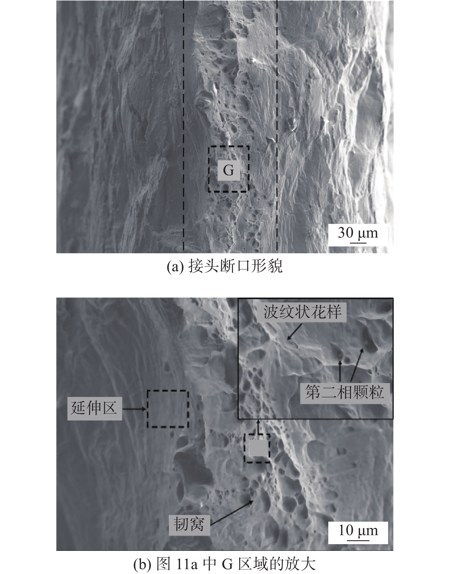
接头的拉伸断口形貌如图11所示. 断口的局部区域存在韧窝,韧窝的底部有一些第二相颗粒,它们导致了微孔洞的形成. 虽然韧窝的分布并不广泛,但断口上存在着韧性断裂的另一个重要特征−延伸区[27],如图11b所示. 当塑性变形发生时,位错沿多个滑移系交滑移,形成波纹状花样. 随着变形的不断进行,波纹状花样平坦化,最终在断口上形成延伸区.
![]() 图 11 断口形貌Figure 11. Fracture morphology. (a) fracture morphology of the tensile specimen;(b) magnified views of zone G in Fig.11a
图 11 断口形貌Figure 11. Fracture morphology. (a) fracture morphology of the tensile specimen;(b) magnified views of zone G in Fig.11a3. 结论
(1) 使用纯铜焊丝获得了无缺陷的T2紫铜/316L不锈钢异质金属钨极氩弧焊接头. 拉伸试验中各接头均断裂在铜侧热影响区,呈现典型的韧性断裂特征. 接头抗拉强度为220 MPa,达到铜母材强度的81.7%.
(2) 以铜为基体的焊缝中分布着大量由铁-铜液相分离形成的富铁球. 在铁-铜初次液相分离形成的富铁球内还分布着Fe-Cr-Mo析出相和标志着铁-铜二次液相分离的富铜相. 富铁球内的析出相在表面能梯度和密度差的作用下,向富铁球中心呈球状聚集.
(3) 填充铜焊丝时,熔池边缘形成了非等温边界. 接头铜/钢界面附近液态钢母材的温度高于熔池主体的温度,在熔池对流作用下形成岛状和半岛状未混溶区.
-
![]()
图 1 焊缝及接头的宏观形貌
Figure 1. Appearance and cross-section morphology of the weld. (a) top appearance of weld; (b) back appearance of weld; (c) cross-section morphology of weld
![]()
图 2 焊缝特征组织
Figure 2. Characteristic microstructure in the weld. (a) Fe-rich spherulite; (b) internal precipitate
![]()
图 3 富铁球内析出相元素分布
Figure 3. Elemental distribution of precipitates in Fe-rich spherulite
![]()
图 4 富铁球演化阶段
Figure 4. Evolution stages of Fe-rich spherulites. (a) schematic movement process of precipitates in Fe-rich spherulite; (b) nano-sized precipitates; (c) nano-sized and bulky precipitates; (d) nano-sized and coarsened bulky precipitates; (e) bulky precipitates
![]()
图 5 焊缝不同区域的富铁球
Figure 5. Fe-rich spherulites at different sites. (a) vicinity of BM; (b) center of WZ; (c) Fe-rich spherulites in the vicinity of BM; (d) Fe-rich spherulites in the center of WZ
![]()
图 6 焊缝特征组织形貌
Figure 6. Morphology of characteristic microstructure in the weld. (a) Fe-rich dendrites in the weld; (b) steel droplets detached from UMZ
![]()
图 7 铜焊缝/钢母材界面形貌
Figure 7. Weld/316L SS interface achieved by Cu filler. (a) macro structure; (b) island and peninsular UMZ; (c) zone without UMZ; (d) thin UMZ
![]()
图 8 TLW < TLB时宏观偏析原理
Figure 8. Mechanism for macrosegregation under the condition of TLW < TLB. (a) schematic diagram of solidification front;(b) schematic illustration of welding pool; (c) formation of UMZ; (d) formation of peninsula and island UMZ
![]()
图 11 断口形貌
Figure 11. Fracture morphology. (a) fracture morphology of the tensile specimen;(b) magnified views of zone G in Fig.11a
表 1 母材和焊丝的化学成分(质量分数, %)
Table 1 Chemical compositions of base materials and filler wires
材料 Ni Cr Mo Mn Si P S Sn Fe Cu 316L不锈钢 10.56 17.50 2.07 1.06 0.43 $\leqslant $ 0.03$\leqslant $ 0.03— 余量 0.05 T2紫铜 — — — — $\leqslant $ 0.03$\leqslant $ 0.01$\leqslant $ 0.01— — 余量 Cu焊丝 — — — $\leqslant $ 0.5$\leqslant $ 0.5— — ≤1.0 — 余量  下载: 导出CSV
表 2 焊接工艺参数
Table 2 Welding experiment paraments
气体流量Q/(L·min−1) 焊接电流
I/A送丝速度
vg/(mm·s−1)行走速度
vw/(mm·s−1)10 130 6 1
下载: 导出CSV
表 3 富铁球EPMA定量分析结果
Table 3 EPMA quantitative analysis results of Fe-rich spherulite
位置 元素含量(原子分数, %) 可能相 Fe Cu Cr Ni Mo A 10.2 80.4 4.2 1.5 3.6 富铁ε-Cu B 48.7 2.0 26.0 2.4 20.9 σ C 66.1 5.6 18.9 3.9 5.4 α-(Fe, Cr) D 2.8 95.1 0.7 1.3 0.0 ε-Cu
下载: 导出CSV
表 4 不同位置处富铁相成分(质量分数, %)
Table 4 Composition of Fe-rich phases in different positions
位置 Fe Cu Cr Ni Mo E 66.5 6.7 18.8 3.5 0.5 F 69.2 2.7 18.2 7.0 2.9 316L母材 70.1 0.1 17.4 10.3 1.9
下载: 导出CSV
表 5 接头软化区显微硬度及宽度
Table 5 Microhardness and width of softened zone on copper side
软化区硬度
H(HV0.05)软化区宽度
D/mm热影响区宽度
d/mm62 9.5 2.5
下载: 导出CSV
-
[1] Yingyot P, Samrerng D, Denchay B, et al. Gas tungsten arc welding of copper to stainless steel for ultra-high vacuum applications[J]. Journal of Materials Processing Technology, 2020, 277: 116490. doi: 10.1016/j.jmatprotec.2019.116490
[2] Wang Y, Li X, Wang Xiao, et al. Fabrication of a thick copper-stainless steel clad plate for nuclear fusion equipment by explosive welding[J]. Fusion Engineering and Design, 2018, 137: 91 − 96. doi: 10.1016/j.fusengdes.2018.08.017
[3] Nguyen Q, Azadkhou A, Akbari M, et al. Experimental investigation of temperature field and fusion zone microstructure in dissimilar pulsed laser welding of austenitic stainless steel and copper[J]. Journal of Manufacturing Processes, 2020, 56: 206 − 215. doi: 10.1016/j.jmapro.2020.03.037
[4] Magnabosco I, Ferro P, Bonollo F, et al. An investigation of fusion zone microstructures in electron beam welding of copper−stainless steel[J]. Materials Science and Engineering:A, 2006, 424: 163 − 173. doi: 10.1016/j.msea.2006.03.096
[5] 吕世雄, 宋建岭, 杨士勤. 钢基体表面TIG铜堆敷层泛铁规律分析[J]. 焊接学报, 2008, 29(8): 85 − 88. doi: 10.3321/j.issn:0253-360X.2008.08.022 Lü Shixiong, Song Jianling, Yang Shiqin. Content of Fe in TIG cladding copper alloy layer on surface of steel[J]. Transactions of the China Welding Institution, 2008, 29(8): 85 − 88. doi: 10.3321/j.issn:0253-360X.2008.08.022
[6] 彭迟, 程东海, 陈益平, 等. 铜/钢异种材料等离子弧焊接头显微组织分析[J]. 材料科学与工艺, 2015, 23(4): 105 − 110. doi: 10.11951/j.issn.1005-0299.20150418 Peng Chi, Cheng Donghai, Chen Yiping, et al. Microstructure of dissimilar material joint with T2 copper and steel 304 for plasma arc welding[J]. Materials Science & Technology, 2015, 23(4): 105 − 110. doi: 10.11951/j.issn.1005-0299.20150418
[7] 李继红, 张云龙, 杜明科, 等. 合金元素对铜/钢接头连接机理及性能的影响[J]. 焊接学报, 2021, 42(3): 34 − 41. Li Jihong, Zhang Yunlong, Du Mingke, et al. Effect of alloy elements on the interface connection mechanism and properties of copper/ steel welded joints[J]. Thansactions of the China Welding Institution, 2021, 42(3): 34 − 41.
[8] Liu S, Jie J, Dong B, et al. Novel insight into evolution mechanism of second liquid-liquid phase separation in metastable immiscible Cu-Fe alloy[J]. Materials and Design, 2018, 156: 71 − 81. doi: 10.1016/j.matdes.2018.06.044
[9] Chen S, Huang J, Xia J, et al. Microstructural characteristics of a stainless steel/copper dissimilar joint made by laser welding[J]. Metallurgical and Materials Transactions A, 2013, 44(8): 3690 − 3696.
[10] Cheng Z, Huang J H, Ye Z, et al. Microstructures and mechanical properties of copper-stainless steel buttwelded joints by MIG-TIG double-sided arc welding[J]. Journal of Materials Processing Technology, 2019, 265: 87 − 98. doi: 10.1016/j.jmatprotec.2018.10.007
[11] Chen S H, Huang J H, Xia J, et al. Influence of processing parameters on the characteristics of stainless steel/copper laser welding[J]. Journal of Materials Processing Technology, 2015, 222: 43 − 51. doi: 10.1016/j.jmatprotec.2015.03.003
[12] Meng Y, Li X, Gao M, et al. Microstructures and mechanical properties of laser-arc hybrid welded dissimilar pure copper to stainless steel[J]. Optics and Laser Technology, 2019, 111: 140 − 145. doi: 10.1016/j.optlastec.2018.09.050
[13] Guo S, Zhou Q, Kong J, et al. Effect of beam offset on the characteristics of copper/304stainless steel electron beam welding[J]. Vacuum, 2016, 128: 205 − 212. doi: 10.1016/j.vacuum.2016.03.034
[14] Roy C, Pavanan V V, Vishnu G, et al. Characterization of metallurgical and mechanical properties of commercially pure copper and AISI 304 dissimilar weldments[J]. Procedia Materials Science, 2014, 5: 2503 − 2512. doi: 10.1016/j.mspro.2014.07.502
[15] Wang C P, Liu X J, Ohnuma I, et al. Thermodynamic database of the phase diagrams in Cu-Fe base ternary systems[J]. Journal of Phase Equilibria and Diffusion, 2004, 25: 320 − 328. doi: 10.1007/s11669-004-0150-5
[16] Cao S, Zhao J C. Determination of the Fe-Cr-Mo phase diagram at intermediate temperatures using dual-anneal diffusion multiples[J]. Journal of Phase Equilibria and Diffusion, 2016, 37: 25 − 38. doi: 10.1007/s11669-015-0423-1
[17] Gao X L, Li L K, Liu J, et al. Effect of laser offset on microstructure and mechanical properties of laser welding of pure molybdenum to stainless steel[J]. International Journal of Refractory Metals & Hard Materials, 2020, 88: 105186.
[18] Yang Y, Busby J T. Thermodynamic modeling and kinetics simulation of precipitate phases in AISI 316 stainless steels[J]. Journal of Nuclear Materials, 2014, 448: 282 − 293. doi: 10.1016/j.jnucmat.2014.02.008
[19] Wu Y H, Wang W L, Chang J, et al. Evolution kinetics of microgravity facilitated spherical macrosegregation within immiscible alloys[J]. Journal of Alloys and Compounds, 2018, 763: 808 − 814. doi: 10.1016/j.jallcom.2018.06.022
[20] Alvaro M, Stefan K, Diego N, et al. Solutal Marangoni flow as the cause of ring stains from drying salty colloidal drops[J]. Physical Review Fluids, 2019, 4: 041601. doi: 10.1103/PhysRevFluids.4.041601
[21] Liu N. Investigation on the phase separation in undercooled Cu-Fe melts[J]. Journal of Non-Crystalline Solids, 2012, 358: 196 − 199. doi: 10.1016/j.jnoncrysol.2011.09.009
[22] Shimizu R, Tanaka H. A novel coarsening mechanism of droplets in immiscible fluid mixtures[J]. Nature Communications, 2015, 6: 7407. doi: 10.1038/ncomms8407
[23] He J, Zhao J Z, Lorenz Ratke. Solidification microstructure and dynamics of metastable phase transformation in undercooled liquid Cu-Fe alloys[J]. Acta Materialia, 2006, 54: 1749 − 1757. doi: 10.1016/j.actamat.2005.12.023
[24] Yang Y K, Kou S. Mechanisms of macrosegregation formation near fusion boundary in welds made with dissimilar filler metals[C]//Materials Science and Technology Conference and Exhibition, MS and T'07-Exploring Structure, Processing, and Applications Across Multiple Materials Systems. 2007, 5: 3201−3212.
[25] Soysal T, Kou S, Tat D, et al. Macrosegregation in dissimilar-metal fusion welding[J]. Acta Materialia, 2016, 110: 149 − 160. doi: 10.1016/j.actamat.2016.03.004
[26] Xue P, Xiao B L, Zhang Q, et al. Achieving friction stir welded pure copper joints with nearly equal strength to the parent metal via additional rapid cooling[J]. Scripta Materialia, 2011, 64: 1051 − 1054. doi: 10.1016/j.scriptamat.2011.02.019
[27] Ebara R, Takeda K, Ishibashi Y, et al. Microfractography in failure analysis of cold forging dies[J]. Engineering Failure Analysis, 2009, 16: 1968 − 1976. doi: 10.1016/j.engfailanal.2008.10.023
-
期刊类型引用(0)
其他类型引用(3)


计量
- 文章访问数: 263
- HTML全文浏览量: 39
- PDF下载量: 25
- 被引次数: 3
