
Formability, microstructure and mechanical properties of nano-treated Al-Zn-Mg-Cu alloy fabricated by wire arc additive manufacturing
-
摘要:
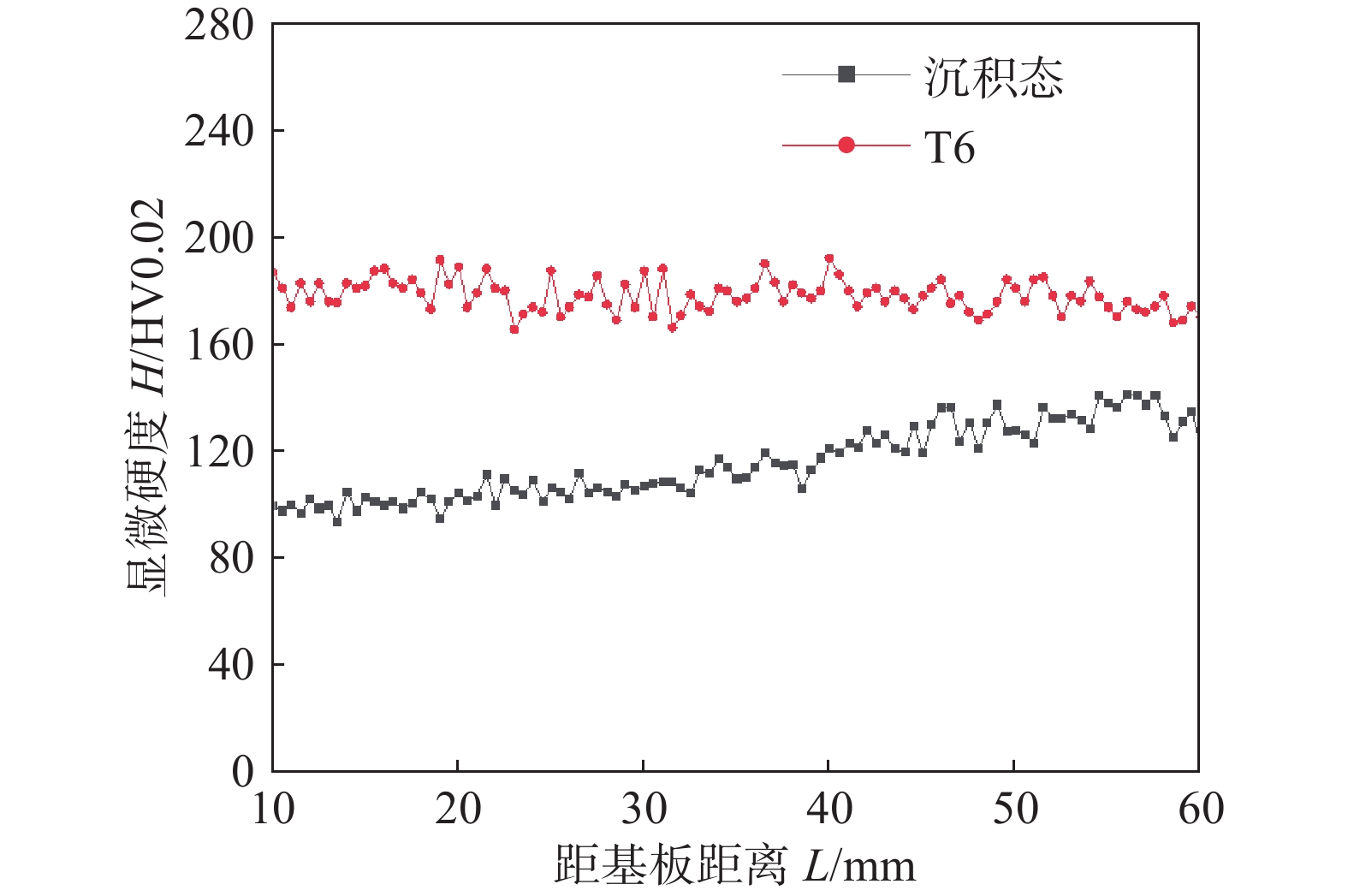
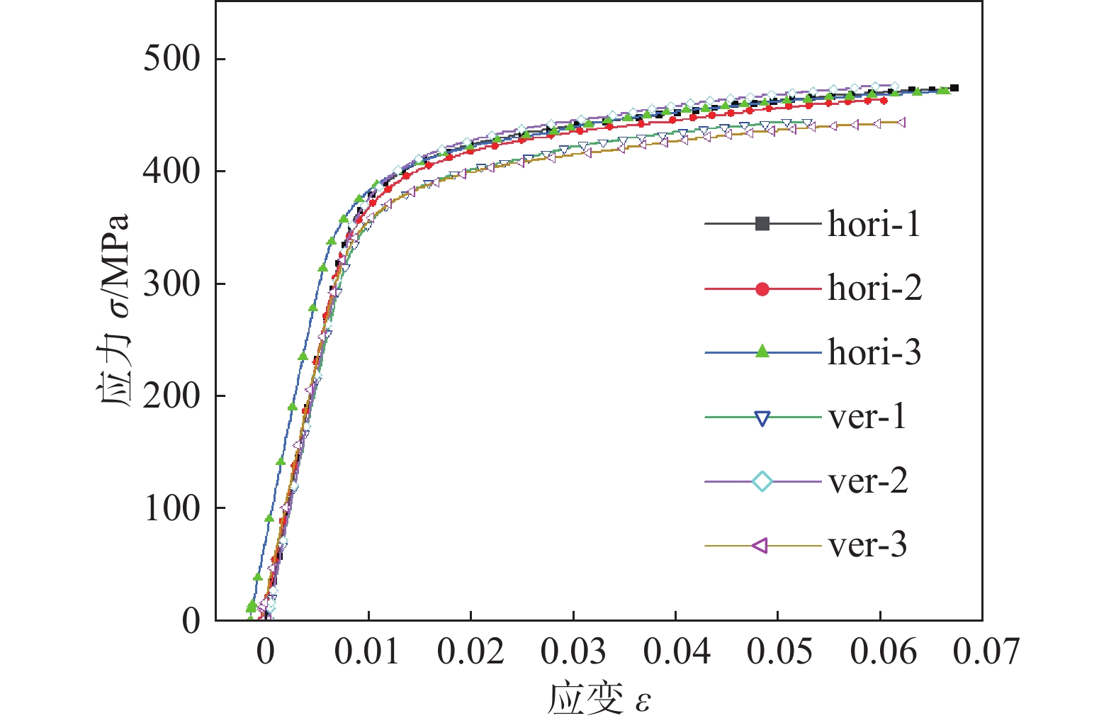
采用电弧熔丝增材制造技术(WAAM)对纳米改性Al-Zn-Mg-Cu 合金进行成形试验,分析了焊接电流、焊接速度、沉积路径、层间等待时间对成形性能的影响. 结果表明,在焊接电流190 A、焊接速度350 mm/min、往复沉积、层间等待时间为90 s时合金具有良好的成形性能. 对制备的直壁墙体进行了沉积后热处理,对不同状态合金的组织和性能进行了研究. 沉积态及热处理态合金显微组织均具有优异的各向同性,由细小的、无明显取向的等轴晶组成. T6处理显著提高了沉积态合金的硬度及力学性能,T6处理后平均硬度为178.3 HV,较沉积态提升61%,沿横向抗拉强度(Rm)、屈服强度(ReL)与断后伸长率(A)分别为469.7(±5.1) MPa,366.3(±1.4) MPa与6.4(±0.4)%,沿纵向抗拉强度(Rm)、屈服强度(ReL)与断后伸长率(A)分别为454.3(±18.8) MPa,364.7(±16.7) MPa与5.9(±0.5)%,具有良好的力学性能各向同性.
-
关键词:
- 电弧熔丝增材制造 /
- 纳米改性 /
- Al-Zn-Mg-Cu 合金 /
- 成形性能 /
- 组织和性能
Abstract:Wire arc additive manufacturing(WAAM) was utilized to fabricate the nano-treated Al-Zn-Mg-Cu alloy. Effects of fabrication parameters on WAAM formability are systematically investigated. The results show that the nano-treated Al-Zn-Mg-Cu alloy is well formed by alternative path under the following parameters: welding current 190 A, welding speed 350 mm/min, dwell time 90 s. Post-deposition heat treatment is employed to further modify the microstructure and the mechanical performance. The WAAMed Al-Zn-Mg-Cu alloys at both as-deposited and heat-treated states exhibit homogeneous microstructure composed of fine equiaxed grains without preferred orientation. T6 heat treatment significantly improves the microhardness and mechanical properties of the as-deposited alloy. The microhardness of the T6 treated alloy reaches 178.3 HV, which is 61% higher than that of the as-deposited sample. The ultimate tensile strength, yield strength, elongation of the T6 treated alloy along horizontal and vertical directions are 469.7(±5.1) MPa, 366.3(±1.4) MPa, 6.4 (±0.4) % and 454.3(±18.8) MPa, 364.7(±16.7) MPa, 5.9 (±0.5)% respectively, demonstrating that the WAAMed nano-treated Al-Zn-Mg-Cu alloy has excellent mechanical isotropy.
-
0. 序言
CMT Cycle Step焊接工艺是通过控制每个焊点的熔滴数,以及焊点与焊点之间的间隔时间,来获得焊缝表面特征纹路呈鱼鳞纹状的焊缝,既继承了CMT焊接工艺低热输入、无飞溅[1-3]等特点,又能够进一步控制热输入,在点焊、热敏感材料焊接、电弧增材制造等领域具有广阔的应用前景.
众所周知,焊接工艺参数对焊缝成形的影响较大,同时成形又会影响焊缝质量[4]. 目前关于CMT焊接工艺对焊缝成形影响的研究报道较多,Kannan等人[5]研究了CMT工艺下弧长修正对AISI316L焊缝成形及性能的影响,结果表明,随着弧长修正的增大,熔宽逐渐增大,当弧长校正在0% ~ 20%的正范围内时,焊接接头的抗拉强度增加. 张栋等人[6]研究了高速CMT焊接条件下,焊接工艺参数对焊缝成形的影响,结果发现三个控制因素对焊缝成形的主次顺序为:峰值送丝速度,峰值持续时间,峰值电流. 刘志森等人[7]采用正交试验研究了CMT焊接工艺下送丝速度、焊接速度和层间温度对焊缝成形尺寸的影响规律,结果表明通过改变焊接速度可以引起熔宽和余高的显著变化,层间温度对余高和第2层增高影响较小. Yin等人[8]研究了双丝CMT焊接工艺参数对5083铝合金焊缝成形尺寸的影响,并拟合出能够预测焊缝成形的回归方程.
与普通CMT焊接工艺相比,CMT Cycle Step新增了熔滴数量、间隔时间和焊点数量等工艺参数,且表面呈“鱼鳞纹状”特征. 而目前针对CMT Cycle Step工艺对焊缝成形影响的研究未见报道. 为系统研究CMT Cycle Step工艺参数对焊缝成形的影响,文中通过正交试验法,探究了CMT Cycle Step工艺参数对焊缝表面特征纹路的影响规律,并建立多元工艺参数与焊缝成形尺寸的回归方程,为预测焊缝形貌以及优化焊接工艺提供理论依据.
1. 试验方法
图1为CMT Cycle Step焊接工艺原理示意图,可以看出,CMT Cycle Step焊接工艺参数主要包括送丝速度(wire speed)、熔滴数量(CMT cycles)、间隔时间(pause time interval)和焊点数量(interval cycles). CMT Cycle Step工艺下连续焊缝的表面由两两相邻的焊点搭接形成鱼鳞纹特征纹路,相邻鱼鳞纹的间距为鱼鳞纹步长S,搭接处的高度差即为鱼鳞纹高度差Δh.
![]() 图 1 CMT Cycle Step工艺原理示意图Figure 1. Schematic diagram of CMT cycle step process principle
图 1 CMT Cycle Step工艺原理示意图Figure 1. Schematic diagram of CMT cycle step process principle熔滴数量用于设置每个焊点的熔滴个数,取值越大焊点越大,熔滴数量可调节范围为50 ~ 2 000. 间隔时间用于设置焊点之间的间隔时间,间隔时间越长,焊点之间间距越大,间隔时间调节范围为0.01 ~ 2 s. 为获得成形良好的连续焊缝,熔滴数量一般取50 ~ 250,间隔时间一般取0.1 ~ 0.5 s. 焊点数量用于设置焊点总个数,决定焊缝长度,对焊缝成形影响极小,文中不做研究. 另外,焊接速度对焊缝成形影响较大[9-10],综合考虑,主要研究送丝速度、焊接速度、熔滴数量和间隔时间四个参数对焊缝熔宽B、堆焊层厚度h、鱼鳞纹步长S以及鱼鳞纹高度差Δh的影响.
试验采用ABB IRB 2600机器人,集成Fronius全数字化TPS500i焊机,采用一元化控制调节焊接电流、电压与送丝速度,其各参数间的关系如图2所示. 采用直径1.0 mm的ER316L不锈钢焊丝,试板材料为316L不锈钢,保护气采用20 L/min的氩气.
![]() 图 2 送丝速度与焊接电流、焊接电压的关系Figure 2. Relationship between wire feeding speed and welding current and voltage
图 2 送丝速度与焊接电流、焊接电压的关系Figure 2. Relationship between wire feeding speed and welding current and voltage采用正交试验法进行CMT Cycle Step平板堆焊试验,考察送丝速度、焊接速度、熔滴数量和间隔时间对焊缝成形的影响,4个因素分别选取5个等距的水平,具体见表1,采用L25正交表设计试验.
表 1 正交试验表Table 1. Orthogonal test table水平 送丝速度X1/(m∙min−1) 焊接速度X2/(mm∙s−1) 熔滴数量X3 间隔时间X4/s 1 7.0 2 50 0.1 2 8.5 3 100 0.2 3 10.0 4 150 0.3 4 11.5 5 200 0.4 5 13.0 6 250 0.5 2. 试验结果与讨论
2.1 试验结果
CMT Cycle Step工艺下焊缝成形如图3所示,鱼鳞纹步长S、鱼鳞纹高度差Δh、熔宽B、堆焊层厚度h测量结果见表2,正交试验结果的分析见表3. 从表3各参数极差可以看出,焊接速度对焊缝鱼鳞纹步长S的影响最大,其次是熔滴数量 、间隔时间和送丝速度;间隔时间对鱼鳞纹高度差Δh的影响最大,其次是焊接速度、送丝速度和熔滴数量;送丝速度对焊缝熔宽B的影响最大,其次是焊接速度、熔滴数量和间隔时间;焊接速度对堆焊层厚度h的影响最大,其次是熔滴数量、送丝速度和间隔时间.
表 2 正交试验测量结果Table 2. Results of the orthogonal experiments序号 因素X1
水平因素X2
水平因素X3
水平因素X4
水平鱼鳞纹步长
S/mm鱼鳞纹高度差
Δh/mm熔宽
B/mm堆焊层厚度
h/mm1 1 1 1 1 1.07 0.01 6.80 5.61 2 1 2 2 2 3.52 0.12 6.20 4.84 3 1 3 3 3 4.82 0.24 6.29 4.02 4 1 4 4 4 9.44 0.46 6.05 3.54 5 1 5 5 5 14.52 1.12 5.70 3.04 6 2 1 2 3 2.55 0.10 8.62 5.85 7 2 2 3 4 5.53 0.44 7.86 4.80 8 2 3 4 5 9.12 0.51 7.89 4.41 9 2 4 5 1 9.55 0.06 7.65 4.16 10 2 5 1 2 4.36 0.34 5.72 3.13 11 3 1 3 5 4.02 0.20 10.50 5.74 12 3 2 4 1 5.13 0.06 10.84 5.44 13 3 3 5 2 9.81 0.16 9.76 5.10 14 3 4 1 3 3.47 0.32 6.54 3.78 15 3 5 2 4 8.06 0.42 6.96 3.24 16 4 1 4 2 3.93 0.04 13.14 6.50 17 4 2 5 3 7.32 0.24 12.32 5.58 18 4 3 1 4 3.54 0.22 8.12 3.72 19 4 4 2 5 7.08 0.43 8.98 3.73 20 4 5 3 1 8.30 0.16 9.07 3.94 21 5 1 5 4 3.90 0.11 14.00 6.72 22 5 2 1 5 3.35 0.22 8.60 4.38 23 5 3 2 1 3.87 0.10 11.58 4.81 24 5 4 3 2 6.91 0.24 10.89 4.30 25 5 5 4 3 11.50 0.36 9.84 3.90 表 3 正交试验结果分析Table 3. Analysis of the orthogonal experiments分析指标 分析值 X1 X2 X3 X4 因素主次 S k1 6.67 3.09 3.15 5.58 X2 X3 X4 X1 k2 6.22 4.97 5.01 5.70 k3 6.09 6.23 5.91 5.93 k4 6.03 7.29 7.82 6.09 k5 5.90 9.34 9.02 7.61 极差R 0.77 6.25 5.87 2.03 Δh k1 0.39 0.09 0.22 0.07 X4 X2 X1 X3 k2 0.29 0.21 0.23 0.18 k3 0.23 0.24 0.25 0.25 k4 0.21 0.30 0.28 0.33 k5 0.20 0.48 0.33 0.49 极差R 0.19 0.39 0.11 0.42 B k1 6.20 10.61 7.15 9.18 X1 X2 X3 X4 k2 7.54 9.16 8.46 9.14 k3 8.92 8.72 8.92 8.72 k4 10.32 8.02 9.55 8.59 k5 10.98 7.45 9.88 8.33 极差R 4.78 3.16 2.73 0.85 h k1 4.21 6.08 4.12 4.79 X2 X3 X1 X4 k2 4.47 5.01 4.49 4.77 k3 4.66 4.41 4.56 4.62 k4 4.69 3.90 4.75 4.40 k5 4.82 3.45 4.92 4.26 极差R 0.61 2.63 0.80 0.53 2.2 工艺参数对焊缝表面特征纹路的影响
CMT Cycle Step工艺参数对焊缝表面特征纹路的影响如图4所示. 图4a给出了焊缝表面特征纹路—鱼鳞纹步长S随各参数的变化曲线,可以看出,随着熔滴数量和焊接速度的增加,焊缝表面鱼鳞纹步长S越长,是因为随着熔滴数量的增加,单个焊点持续焊接时间越长,焊点之间的间距越大;焊接速度增加时,也会使焊点之间间距增大,所以鱼鳞纹步长S随之增加. 随着间隔时间的增加,鱼鳞纹步长S逐渐增大,是因为间隔时间越长,焊点之间间距越大,也会使得鱼鳞纹步长S增加. 送丝速度对鱼鳞纹步长S的影响较小,主要是因为送丝速度的变化不会导致焊点之间的间距发生明显改变.
![]() 图 4 工艺参数对焊缝表面特征纹路的影响Figure 4. Influence of process parameters on characteristic lines of weld surface. (a) Influence of process parameters on S; (b) Influence of process parameters on Δh
图 4 工艺参数对焊缝表面特征纹路的影响Figure 4. Influence of process parameters on characteristic lines of weld surface. (a) Influence of process parameters on S; (b) Influence of process parameters on Δh图4b给出了鱼鳞纹高度差Δh随各参数的变化曲线. 采用CMT Cycle Step工艺连续焊接时,焊缝表面鱼鳞纹高度差Δh是由相邻焊点搭接形成的,前一焊点收弧形成弧坑,后一焊点在弧坑处起弧,搭接处高度难以与中间平稳段一致,因此会存在一定高度差. 由图4b可以看出,焊接速度和间隔时间增加,鱼鳞纹高度差Δh呈逐渐增大的趋势,是因为焊接速度和间隔时间增加时,后一焊点与前一焊点的搭接量减小,导致鱼鳞纹高度差Δh增大.
由此可见,适当减小焊接速度和间隔时间,可有效提高焊缝表面平整度. 送丝速度、熔滴数量与单个焊点内填充金属量相关,对焊点之间搭接量影响很小,因此对鱼鳞纹高度差Δh基本没有影响.
为进一步量化工艺参数对焊缝表面特征纹路的影响,采用回归模型对数据进行拟合,由图4b可以看出鱼鳞纹高度差Δh随工艺参数变化的范围很小,因此只进一步探究各因素与鱼鳞纹步长S之间的关系. 对正交试验数据进行回归分析,发现鱼鳞纹步长S与焊点间隔距离相关,熔滴数量决定单个焊点持续焊接时间,焊点间隔距离与焊接速度和单个焊点持续焊接时间的乘积相关,鱼鳞纹步长S与熔滴数量和焊接速度的乘积相关,所以采用二次回归模型进行拟合,即
$$ S = a + \sum\limits_{i = 1}^4 {{b_i}{x_i}} + \sum\limits_{i = 1}^4 {\sum\limits_{j = 1}^4 {{b_i}_j{x_i}} } {x_j} + \sum\limits_{i = 1}^4 {{b_i}_i{x_i}^2} $$ (1) 式中:a为常数项系数,bi为一次项系数,bij为交叉项系数,bii为二次项系数[11]. 为保证回归数学模型的可靠性,利用F检验法检验回归模型及其包括的各个因素的显著性,对影响力较弱的因素予以简化[12]. 经简化后,最终得到焊缝鱼鳞纹步长S与送丝速度、焊接速度、熔滴数量和间隔时间之间的回归方程,即
$$ \begin{split} & S = - 0.208 + 0.042{X_1} + 0.069{X_2} - 0.000\;5{X_3} + \\&\qquad 0.384{X_4} + 0.007{X_2}{X_3} + 1.02{X_2}{X_4} \end{split} $$ (2) 图5为回归模型计算与试验测量焊缝表面鱼鳞纹特征尺寸对比图,通过对比计算值和试验测量值来验证回归方程拟合准确性,各点距离图5对角线越近,说明计算值与试验测量值偏差越小,方程拟合程度越高,观察发现各试验点均在对角线附近,可见,回归模型计算值与试验测试结果具有较好的对应关系.
![]() 图 5 回归模型计算值与鱼鳞纹步长S测量值对比图Figure 5. Comparison between calculated value of regression model and measured value of fish scale step S
图 5 回归模型计算值与鱼鳞纹步长S测量值对比图Figure 5. Comparison between calculated value of regression model and measured value of fish scale step S2.3 工艺参数对焊缝成形尺寸的影响
图6为工艺参数对焊缝成形尺寸的影响规律图. 由图6a、6b可以看出,随着送丝速度的增加,焊缝熔宽B、堆焊层厚度h逐渐增大;随着焊接速度的增大,焊缝熔宽B、堆焊层厚度h逐渐减小. 与MIG等其他传统焊接方法规律一致,与文献[7]结果一致. 随着熔滴数量的增大,焊缝熔宽B、堆焊层厚度h逐渐增大,这是由于熔滴数量越大,单个焊点内熔滴个数越多,燃弧持续时间越长,因此焊缝熔宽B、堆焊层厚度h越大. 随着间隔时间的增大,焊缝熔宽B、堆焊层厚度h基本不变,这是由于间隔时间只会影响各焊点之间的间距,对焊缝成形尺寸影响较小.
![]() 图 6 工艺参数对焊缝成形尺寸的影响Figure 6. Effect of the welding parameters on bead forming dimension. (a) influence of process parameters on B; (b) influence of process parameters on h
图 6 工艺参数对焊缝成形尺寸的影响Figure 6. Effect of the welding parameters on bead forming dimension. (a) influence of process parameters on B; (b) influence of process parameters on h为进一步考察送丝速度、焊接速度、熔滴数量和间隔时间四个参数对焊缝成形尺寸熔宽B和堆焊层厚度h的影响,采用多元线性回归方法对正交试验数据进行拟合分析,得到熔宽B、堆焊层厚度h的回归方程,即
$$ B = 2.272 - 0.822{X_1} - 0.745{X_2} + 0.013{X_3} - 2.252{X_4} $$ (3) $$ h = 6.03 + 0.096{X_1} - 0.637{X_2} + 0.004{X_3} - 1.434{X_4} $$ (4) 图7为利用回归模型计算的焊缝成形尺寸计算值与试验测量获得的焊缝成形尺寸实测值的对比图,可以看出,回归模型计算数值与试验测试结果具有较好的对应关系,由此可以说明回归方程能够一定程度上反映送丝速度、焊接速度、熔滴数量和间隔时间4个工艺参数与焊缝熔宽B、堆焊层厚度h之间的关系.
![]() 图 7 回归模型计算与焊缝成形实测值对比图Figure 7. Comparison between regression model calculation and measured value of weld formation. (a) comparison between calculated and experimental values of weld width; (b) comparison between calculated and experimental values of weld overlay thickness
图 7 回归模型计算与焊缝成形实测值对比图Figure 7. Comparison between regression model calculation and measured value of weld formation. (a) comparison between calculated and experimental values of weld width; (b) comparison between calculated and experimental values of weld overlay thickness3. 结论
(1) 随着焊接速度、熔滴数量和间隔时间的增大,鱼鳞纹步长S逐渐增大;随着焊接速度和间隔时间的增大,鱼鳞纹高度差Δh呈逐渐增大的趋势. 适当减小焊接速度和间隔时间,可有效减小鱼鳞纹高度差Δh.
(2) 随着送丝速度的增加,焊缝熔宽B、堆焊层厚度h逐渐增大;随着焊接速度的增大,焊缝熔宽B、堆焊层厚度h逐渐减小. 随着熔滴数量的增大,焊缝熔宽B、堆焊层厚度h逐渐增大. 间隔时间对焊缝成形尺寸影响较小.
(3) 通过建立送丝速度、焊接速度、熔滴数量和间隔时间与焊缝表面鱼鳞纹步长S和焊缝成形尺寸之间的回归方程,并对比试验值和预测值,验证了方程的准确性.
-
![]()
图 1 增材过程示意图及试样尺寸(mm)
Figure 1. Schematic of printing process and sample cutting. (a) printing process and samples position; (b) dimensional drawing of tensile specimen
![]()
图 2 不同焊接方向单道多层增材试样宏观形貌
Figure 2. Macro forming morphology of single pass multi-layer additive samples under different welding directions. (a) single direction; (b) reciprocating direction
![]()
图 3 不同层间等待时间单道多层增材试样宏观形貌
Figure 3. Macro forming diagram of single pass multi-layer additive samples with different dwell time. (a) dwell time 30 s;(b) dwell time 60 s;(c) dwell time 90 s;(d) dwell time 120 s
![]()
图 4 试样上部、中部和下部区域的微观组织
Figure 4. Optical microstructure of the top, middle and bottom regions
![]()
图 5 沉积态试样中部SEM形貌
Figure 5. SEM image of the middle part of the as-deposited sample. (a) SEM image at low magnification; (b) SEM image of area 2; (c) SEM image of area 1; (d) SEM image of area 3
![]()
图 6 沉积态EDS能谱图
Figure 6. EDS energy spectrum of as-deposited sample. (a) EDS map of area 2 in Fig.5; (b) EDS map of area 1 in Fig.5
![]()
图 7 试样中部EBSD结果
Figure 7. EBSD characterization of the Middle part of the as-deposited sample. (a) EDSD results of position 1; (b) EDSD results of position 2
![]()
图 8 增材试样T6态金相组织
Figure 8. Metallographic structure of additive samples after T6 heat treatment. (a) low magnification; (b) high magnification
![]()
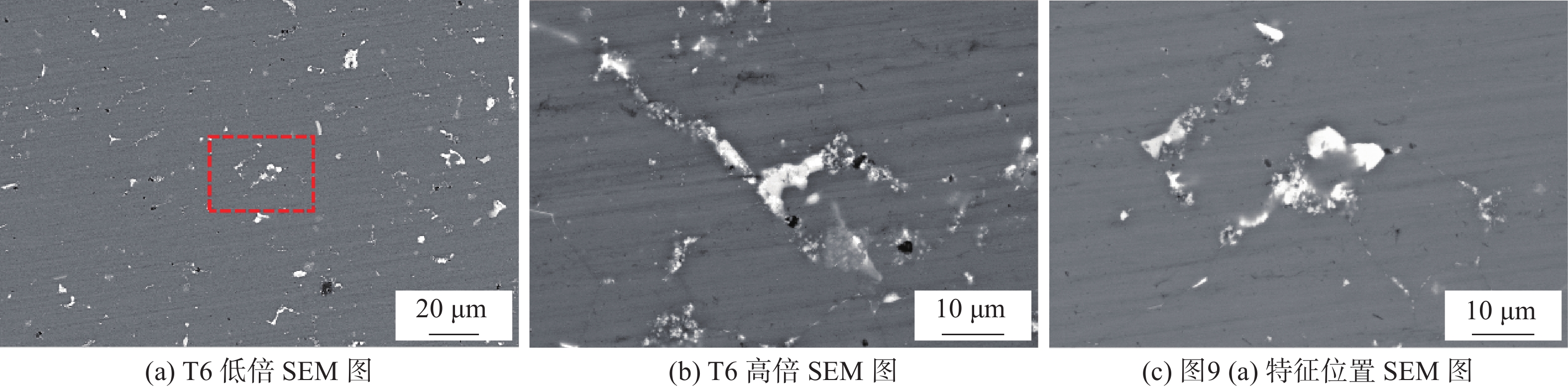
图 9 T6试样中部SEM形貌
Figure 9. SEM image of the middle part of T6 sample. (a) low magnification SEM image of T6 state sample; (b) high magnification SEM image of T6 state sample; (c) SEM image of the dashed rectangular zone in Fig.9(a)
![]()
图 11 T6试样析出相点扫描结果
Figure 11. Spot Scanning Results of precipitation along grain boundaries in T6 Sample. (a) SEM images of grain boundaries precipitates in T6 state sample; (b) EDS results of grain boundaries precipitates
![]()
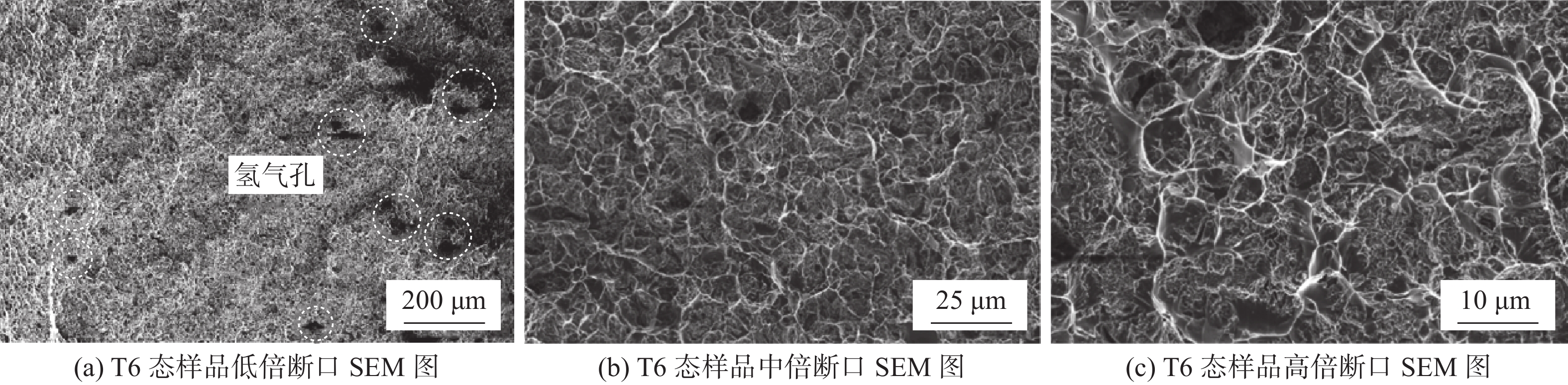
图 14 T6态拉伸断口SEM图
Figure 14. SEM image of T6 state tensile fracture surface. (a) fracture surface SEM images of T6 state sample at low magnification; (b) fracture surface SEM images of T6 state sample at medium magnification; (c) fracture surface SEM images of T6 state sample at high magnification
表 1 焊丝化学成分(质量分数,%)
Table 1 Chemical composition of welding wire
Zn Mg Ti Cu Al 8.6 3.2 1.8 1.8 余量  下载: 导出CSV
表 2 7075铝合金基板化学成分(质量分数,%)
Table 2 Chemical composition of 7075 aluminum alloy substrate
Si Fe Cu Mn Mg Cr Ti Zn Al 0.06 0.16 1.5 0.06 2.62 0.22 0.05 5.59 余量
下载: 导出CSV
表 3 不同焊接电流单道单层焊接试样宏观形貌和截面形貌
Table 3 Macromorphology and cross-sectional morphology of single pass single-layer welding specimens with different welding currents
电流I/A 宏观形貌 截面形貌 熔宽W/mm 余高H/mm 余高系数γ 150 

7.60 4.44 0.58 170 

9.98 3.52 0.35 190 

12.42 3.50 0.28 210 

12.7 3.74 0.29
下载: 导出CSV
表 4 不同焊接速度单道单层焊接试样宏观形貌和截面形貌
Table 4 Macromorphology and cross-sectional morphology of single pass single-layer welding specimens with different welding speeds
焊接速度v/(mm·min−1) 宏观形貌 截面形貌 熔宽W/mm 余高H/mm 余高系数γ 250 

11.26 4.54 0.40 350 

11.90 3.54 0.30 450 

9.72 3.10 0.31 550 

7.85 2.92 0.37
下载: 导出CSV
表 5 增材试样化学成分(质量分数,%)
Table 5 Chemical composition of additive samples
Zn Mg Ti Cu Al 5.22 1.91 1.26 1.98 余量
下载: 导出CSV
表 6 T6态拉伸结果
Table 6 Tensile strength of T6 state samples
方向 抗拉强度
Rm /MPa屈服强度
ReL /MPa断后伸长率
A(%)横向 469.7±5.1 366.3±1.4 6.4±0.4 纵向 454.3±18.8 364.7±16.7 5.9±0.5
下载: 导出CSV
-
[1] 张铭洋, 蒋熠鸣, 王春明, 等. 后热处理对激光焊接7075铝合金显微组织与力学性能影响[J]. 焊接学报, 2022, 43(8): 13 − 18. Zhang Mingyang, Jiang Yiming, Wang Chunming, et al. Effect of post-weld heat treatment on microstructure and mechanical properties of laser welded 7075Al alloy[J]. Transactions of the China Weiding Institution, 2022, 43(8): 13 − 18.
[2] Georgantzia E, Gkantou M, Kamaris G S, et al. Aluminium alloys as structural material: A review of research[J]. Engineering Structures, 2021, 227: 111372 doi: 10.1016/j.engstruct.2020.111372
[3] 林三宝, 夏云浩, 董博伦, 等. 双丝电弧增材制备Al-Mg-Zn-Cu-Sc铝合金工艺与组织性能[J]. 焊接学报, 2022, 43(11): 36 − 42. Lin Sanbao, Xia Yunhao, Dong Bolun, et al. Microstructure and properties of dual-wire arc additive manufacturing of Al-Mg-Zn-Cu-Sc alloy[J]. Transactions of the China Weiding Institution, 2022, 43(11): 36 − 42.
[4] Kanishka K, Acherjee B. Revolutionizing manufacturing: A comprehensive overview of additive manufacturing processes, materials, developments, and challenges[J]. Journal of Manufacturing Processes, 2023, 107: 574 − 619. doi: 10.1016/j.jmapro.2023.10.024
[5] Norrish J, Polden J, Richardson I, et al. A review of wire arc additive manufacturing: development, principles, process physics, implementation and current status[J]. Journal of Physics D: Applied Physics, 2021, 54(47): 473001. doi: 10.1088/1361-6463/ac1e4a
[6] Ramazani H, Kami A, Metal FDM, et al. A new extrusion-based additive manufacturing technology for manufacturing of metallic parts: a review[J]. Progress in Additive Manufacturing, 2022, 7(4): 609 − 626. doi: 10.1007/s40964-021-00250-x
[7] Langelandsvik G, Akselsen O M, Furu T, et al. Review of aluminum alloy development for wire arc additive manufacturing[J]. Materials, 2021, 14(18): 5370. doi: 10.3390/ma14185370
[8] Weman K. Welding processes handbook [M]. Cambridge: Woodhead Publishing Limited, 2011.
[9] Dong B, Cai X, Lin S, et al. Wire arc additive manufacturing of Al-Zn-Mg-Cu alloy: microstructures and mechanical properties[J]. Additive Manufacturing, 2020, 36: 101447. doi: 10.1016/j.addma.2020.101447
[10] Doumenc G, Couturier L, Courant B, et al. Investigation of microstructure, hardness and residual stresses of wire and arc additive manufactured 6061 aluminium alloy[J]. Materialia, 2022, 25: 101520. doi: 10.1016/j.mtla.2022.101520
[11] Hauser T, Reisch R T, Breese P P, et al. Porosity in wire arc additive manufacturing of aluminium alloys[J]. Additive manufacturing, 2021, 41: 101993. doi: 10.1016/j.addma.2021.101993
[12] Ryan E, Sabin T, Watts J, et al. The influence of build parameters and wire batch on porosity of wire and arc additive manufactured aluminium alloy 2319[J]. Journal of Materials Processing Technology, 2018, 262: 577 − 584. doi: 10.1016/j.jmatprotec.2018.07.030
[13] Morais P J, Gomes B, Santos P, et al. Characterisation of a high-performance Al–Zn–Mg–Cu alloy designed for wire arc additive manufacturing[J]. Materials, 2020, 13(7): 1610. doi: 10.3390/ma13071610
[14] Ma C, Chen L, Cao C, et al. Nanoparticle-induced unusual melting and solidification behaviours of metals[J]. Nature Communications, 2017, 8(1): 14178. doi: 10.1038/ncomms14178
[15] Martin J H, Yahata B D, Hundley J M, et al. 3D printing of high-strength aluminium alloys[J]. Nature, 2017, 549(7672): 365 − 369. doi: 10.1038/nature23894
[16] Yuan T, Ren X, Chen S, et al. Al–Zn–Mg–Cu alloy with both high strength and high plasticity fabricated with wire arc additive manufacturing[J]. Science and Technology of Welding and Joining, 2023, 28(1): 81 − 88. doi: 10.1080/13621718.2022.2117532
[17] Xiao F, Wang S, Wang Y, et al. Niobium nanoparticle-enabled grain refinement of a crack-free high strength Al-Zn-Mg-Cu alloy manufactured by selective laser melting[J]. Journal of Alloys and Compounds, 2022, 900: 163427. doi: 10.1016/j.jallcom.2021.163427
[18] Yuan L, Pan Z, Ding D, et al. Fabrication of metallic parts with overhanging structures using the robotic wire arc additive manufacturing[J]. Journal of Manufacturing Processes, 2021, 63: 24 − 34. doi: 10.1016/j.jmapro.2020.03.018
[19] Wu B, Pan Z, Ding D, et al. Effects of heat accumulation on microstructure and mechanical properties of Ti6Al4V alloy deposited by wire arc additive manufacturing[J]. Additive Manufacturing, 2018, 23: 151 − 160. doi: 10.1016/j.addma.2018.08.004
[20] Gupta R, Chaudhari G, Daniel B, et al. Strengthening mechanisms in ultrasonically processed aluminium matrix composite with in-situ Al3Ti by salt addition[J]. Composites Part B: Engineering, 2018, 140: 27 − 34. doi: 10.1016/j.compositesb.2017.12.005
[21] Zhao Kai, T Gao ong, Yang Huabing, et al. Enhanced grain refinement and mechanical properties of a high strength Al-Zn-Mg-Cu-Zr alloy induced by TiC nano-particles[J]. Materials Science and Engineering A, 2021(806): 140852.
[22] 李彩琼, 夏琳, 王明刚, 等. 固溶工艺对Al-Zn-Mg-Cu合金组织与性能的影响[J]. 材料热处理学报, 2023, 44(11): 52 − 61. Li Caiqiong, Xia Lin, Wang Minggang, et al. Effect of solution process on microstructure and properties of Al-Zn-Mg-Cu alloy[J]. Transactions of the China Weiding Institution, 2023, 44(11): 52 − 61.
[23] Chen S, Xu M, Yuan T, et al. Thermal–microstructural analysis of the mechanism of liquation cracks in wire-arc additive manufacturing of Al–Zn–Mg–Cu alloy[J]. Journal of Materials Research and Technology, 2022, 16: 1260 − 1271. doi: 10.1016/j.jmrt.2021.12.016
[24] Tillová E, PanuŠková M. Effect of solution treatment on intermetallic phases morphology in AlSi9Cu3 cast alloy[J]. Metalurgija, 2008, 47(3): 207 − 210.
[25] Ren X, Jiang X, Yuan T, et al. Microstructure and properties research of Al-Zn-Mg-Cu alloy with high strength and high elongation fabricated by wire arc additive manufacturing[J]. Journal of Materials Processing Technology, 2022, 307: 117665. doi: 10.1016/j.jmatprotec.2022.117665
[26] Gu J, Ding J, Williams S W, et al. The effect of inter-layer cold working and post-deposition heat treatment on porosity in additively manufactured aluminum alloys[J]. Journal of Materials Processing Technology, 2016, 230: 26 − 34. doi: 10.1016/j.jmatprotec.2015.11.006
-
期刊类型引用(6)
1. 冯消冰,王建军,王永科,陈苏云,刘爱平. 面向大型结构件爬行机器人智能焊接技术. 清华大学学报(自然科学版). 2023(10): 1608-1625 .  百度学术
百度学术
2. 詹剑良,金浩哲. 六工位焊接电器盒系统设计. 机械制造文摘(焊接分册). 2022(02): 41-44 . 百度学术
3. 李建宇,倪川皓,江亚平,贾小磊. 高强钢小角度坡口深熔焊工艺. 机械制造文摘(焊接分册). 2022(05): 26-30 . 百度学术
4. 周利平,朵丛,韩永刚. 常见焊接接头的机器人焊接工艺设计. 科技视界. 2022(29): 101-103 . 百度学术
5. 刘云鸾,敖三三,罗震,相茜. 焊接与智能制造(下)——第25届北京·埃森焊接与切割展览会焊接国际论坛综述. 焊接技术. 2021(08): 1-3 . 百度学术
6. 洪妍,樊星. 北京·埃森焊接展之焊接智能化. 焊接技术. 2021(S1): 78-82 . 百度学术
其他类型引用(3)


计量
- 文章访问数: 102
- HTML全文浏览量: 33
- PDF下载量: 36
- 被引次数: 9
