
Effect of ultrasonic spinning with welding on the microstructure and mechanical properties of 7075 aluminum alloy welded joints
-
摘要:
随焊超声旋压法是一种机械力场和超声能场相结合,随焊控制薄壁件焊接变形的新方法焊接过程中,在熔池后方的特定塑形恢复温度区间施加超声旋压,一方面试件发生高频超声振动,另一方面通过聚能器的高速旋转使高温金属产生塑性变形. 通过超声振动和旋转挤压的复合作用,延展凝固金属的收缩变形,细化晶粒尺寸,达到控制焊接变形,改善焊接接头微观组织,提升力学性能的作用. 设计搭建随焊超声旋压焊接平台,开展7075铝合金的相关焊接试验,获得变形控制效果与焊枪—聚能器间距关系,对焊接接头进行显微组织和力学性能分析. 电子背散色衍射技术(electron back scatter diffraction,EBSD)结果表明,7075铝合金焊缝区晶粒明显得到细化,平均晶粒尺寸由60减小至46.8 μm,柱状晶数目减少,等轴晶数目增加,焊接接头硬度和抗拉强度均得到提升,焊缝区平均硬度由109.7提高到128 HV,抗拉强度由294.71提高到324.64 MPa.
Abstract:The ultrasonic spinning with welding method is a novel approach combining mechanical force field and ultrasonic energy field to control welding deformation of thin-walled components during welding. Its core lies in applying ultrasonic spinning within the specific plastic recovery temperature range behind the molten pool during the welding process, which generates high-frequency ultrasonic vibration in the workpiece while inducing plastic deformation of high-temperature metal through high-speed rotation of the concentrator. Through the combined action of ultrasonic vibration and rotational compression, this method extends the shrinkage deformation of solidified metal, refines grain size, achieving control of welding deformation, improvement of welded joint microstructure, and enhancement of mechanical properties. An ultrasonic spinning with welding platform was designed and constructed, and relevant welding experiments were conducted on 7075 aluminum alloy. The relationship between deformation control effectiveness and torch-concentrator distance was obtained, while microstructural and mechanical property analyses were performed on the welded joints. Electron back scatter diffraction (EBSD) results demonstrate that the weld zone of 7075 aluminum alloy processed by this method exhibits significant grain refinement, with average grain size decreasing from 60 μm to 46.8 μm, accompanied by reduced columnar crystal quantity and increased equiaxed crystal quantity. The welded joints obtained through this method show improved hardness and tensile strength, with average weld zone hardness increasing from 109.7 HV to 128 HV, and tensile strength rising from 294.71 MPa to 324.64 MPa.
-
0. 序言
随着工业的不断发展,工具在使用过程中难以避免发生磨损,在交变载荷下长期运行也会使工件亚表层萌生裂纹. 例如振动筛、耐磨板、破碎机、平地机刮板等地面接合工具,都是在严重磨损的工况下应用的工具[1]. 应用堆焊修复工艺,有效恢复零部件的尺寸并使得零部件表面获得良好的耐腐蚀、耐磨、耐高温等性能,显著提高服役寿命[2-3]. 近年来,通过向Fe-C-Mo系堆焊合金加入钒(V)元素生成硬度高的团球状VC,提高材料阻挡磨粒的显微切削作用,在复杂的冲击工况下满足较好的耐磨性[4-5]. 目前Fe-C-Mo-V合金系耐磨性的研究主要集中在合金成分调控,缺乏在特定磨损条件下耐磨性能的研究[6-7].
利用熔化极气体保护焊技术(GMAW)制备Fe-C-Mo-V堆焊合金,采用基于GB/T 2611—1992规范下的动载冲击三体磨粒磨损系统,在不同法向冲击能量(1 ~ 7 J)条件下,进行Fe-C-Mo-V堆焊合金的动载冲击磨损试验,研究Fe-C-Mo-V堆焊合金在动载冲击环境下的三体磨粒磨损行为.
1. 试验材料及方法
1.1 试样制备
焊丝选用郑州机械研究所有限公司自制的Fe-C-Mo-V气体保护药芯焊丝,直径ϕ1.6 mm,堆焊母材为Q235钢板,尺寸为220 mm × 160 mm × 25 mm. 堆焊前将母材表面用砂轮打磨出金属光泽,采用熔化极气体保护焊制备熔敷金属,保护气体为95% Ar + 5% CO2. 焊接工艺参数如表1所示,在焊接过程中,采用连续焊三层,每层五道,搭接量为1/3 ~ 1/4,焊前不预热,焊后用玻璃棉包裹缓冷. 堆焊完成后进行熔覆金属的化学成分检测,结果如表2所示.
表 1 焊接工艺参数Table 1. Welding parameter of hardfacing alloys焊接电压 U/V 焊接电流 I/A 焊枪行进速度 v1/(mm·s−1) 气体流量 q/(L·min−1) 单道焊缝宽度 H1/mm 焊缝总厚度S /mm 30 ~ 32 280 ~ 320 3.3 ~ 4.5 15 ~ 17 25 ~ 30 8 ~ 12 表 2 熔敷金属主要化学成分(质量分数,%)Table 2. Chemical composition of deposited metalsC Si Mn Ni Mo V Fe 1.0 ~ 2.5 1.5 ~ 2.0 1.72 ~ 2.0 0.1 ~ 0.5 15.0 ~ 20.0 5.0 ~ 10.0 余量 1.2 试验方法
采用MLD-10型的动载冲击三体磨损试验机进行磨粒磨损试验,磨损试验参数如表3所示,磨粒采用铸造石英砂. 试验过程中冲锤可上移至固定的最大高度后自由落体,使方形上试样冲击旋转的环形下试样,造成冲击磨损,同时在冲锤被提升之前还要发生一段时间的滑动磨损. 冲击能量Ak(J)是通过计算冲锤重量P(N)与冲锤自由落体高度H(mm)的乘积得到. 冲锤重量为100 N时,适用于1 ~ 5 J冲击能量,冲锤重量为160 N时,适用于6 ~ 7 J冲击能量. 试验所需磨损试样用电火花切割技术在堆焊试板上切取规格为30 mm × 10 mm × 10 mm的方形试样,表面粗糙度Ra < 1.6 μm. 下试样为购置的具有良好耐磨性能,受冲击变形量小的NM450钢板,加工成外径ϕ50 mm,内径ϕ30 mm的圆环,一个上试样对应一个下试样. 调整冲锤下落高度实现冲击能量1 ~ 7 J的变化,磨损试验前后,使用AL204型分析天平计算熔敷金属的磨损失重,精确至0.000 1 g,每个冲击能量下重复5次试验,计算失重的平均值.
表 3 磨损试验参数Table 3. Parameters of abrasive wear test磨粒直径D/μm 磨粒流速v2/(g·min−1) 冲锤重量P/N 冲锤下落高度H2/mm 冲击次数T(次) 下试样轴转速n/(r·min−1) 冲击能量Ak/J 460 ~ 540 186 ~ 213 100/160 0 ~ 50 6 000 200 1 ~ 7 熔敷金属的物相组成使用Uitima IV型X射线衍射仪进行检测,参数:Cu-Kα靶,扫描速度5°/min,扫描范围30° ~ 100°. 熔敷金属的显微组织、磨痕微观形貌及磨痕亚表面形貌使用Phenom Pro XL型台式扫描电子显微镜进行观察与分析,使用OLYMPUS LEXT OLS4100型激光共聚焦显微镜配合LEXT分析软件测量磨痕深度(磨损最充分的面与原始表面高度差)以及磨痕面粗糙度. 在未磨损的熔敷金属的预磨面及磨损后的磨痕表面通过Wolpert 401 MVD数显维氏硬度计进行硬度检测,控制载荷1.96 N,保荷15 s.
2. 试验结果及分析
2.1 熔敷金属显微组织及硬度分析
图1为Fe-C-Mo-V堆焊合金的X射线衍射分析结果,可检测到的物相有γ-Fe,α-Fe,马氏体,VC,M2C (M = Fe,Mo)以及M3C (M = Fe,Mo)型碳化物.图2为熔敷金属光学显微镜下的金相组织形貌. 由图2可知,熔敷金属的显微组织主要由三部分构成,奥氏体基体、密集分布在基体上的层片状共晶组织,以及在层片状组织和基体上弥散分布的团块状VC (2 615.43 HV0.2)硬质相. 其中基体中存在合金元素的固溶强化,硬度可达885.5 HV0.2,层片状共晶组织主要为M3C (M = Fe,Mo),Mo2C等的复合物,硬度可达1 240.31 HV0.2.
试验测得堆焊合金熔敷金属的显微硬度为840 ~ 920 HV0.2,尽管密集分布的高硬度团块状VC以及层片状复合碳化物能对基体形成保护,不易产生应力集中,在石英砂冲击磨损环境下能较好抵抗磨粒的侵蚀[8],但奥氏体基体的硬度仍低于石英砂的硬度1 000 ~ 1 200 HV0.2,能够造成充分磨损[9].
2.2 熔敷金属磨损损失结果
不同冲击能量条件下熔敷金属磨损后试样的宏观形貌如图3所示. 由图3可以看到,当冲击能量较小(1 ~ 3 J)时,宏观磨痕整体上呈较明显的圆弧凹形. 当冲击能量较大(4 ~ 7 J)时,宏观磨痕较为平坦,几乎观察不到圆弧凹形.
不同冲击能量条件下熔敷金属磨损损失检测结果如图4所示. 由图4a可以看到,随冲击能量不断增大,熔敷金属磨损失重先显著减小,然后趋于保持较低的水平. 根据磨痕深度测试结果(图4b),可以看到,随冲击能量不断增大,熔敷金属磨痕深度不断下降,说明磨损量减少,磨痕表面平坦. 再结合图4c磨痕表面的粗糙度测量可以看出,随着冲击能量增大,磨痕微观面粗糙度逐渐下降,说明磨损无法进一步剧烈进行.
![]() 图 4 熔敷金属在不同冲击能量下的磨损变化情况Figure 4. Variation trend of wear scar in various normal impact energy of deposited metals. (a) wear loss; (b) wear scar depth; (c) wear roughness
图 4 熔敷金属在不同冲击能量下的磨损变化情况Figure 4. Variation trend of wear scar in various normal impact energy of deposited metals. (a) wear loss; (b) wear scar depth; (c) wear roughness根据能量守恒,在冲击过程中能量存在快速转换,冲击动能可以转变为塑性变形消耗的能量、弹性波动消耗的能量、磨粒破碎所能消耗的能量、摩擦产生的热能以及声能等[10]. 当冲击能量较小(1 ~ 3 J)时,方形上试样沿着圆形下环形试样均匀磨损,接触区域的应力主要是圆形下试样最高点与上块状试样之间的压应力,并随着冲击过程的深入,压应力值迅速上升,最终在试样接触表面形成冲击凹坑[8]. 当冲击能量较大(4 ~ 7 J)时,由于磨粒破碎并散乱分布在上下试样之间,导致在滑动磨损时上下试样接触面积增大,且在反复磨损过程中,磨粒一直把材料推向两边又不断把堆积的材料压平,最终在试样磨损接触表面出现较为平坦的磨损面[9-11]. 因此可以认为,随冲击能量不断增大,堆焊合金的磨损程度逐渐减小,磨粒对合金均匀磨损逐渐减弱.
2.3 磨痕微观形貌检测
取1 和7 J两个典型冲击能量条件下熔敷金属磨痕形貌的微观变化SEM分析结果,如图5所示,其中,图中局部放大如图中右上角所示. 可以看到,在低倍下的熔敷金属磨痕上具有显著的黑色区域,随冲击能量增大,黑色区域面积提高.
![]() 图 5 不同冲击能量下熔敷金属的磨痕的SEM形貌Figure 5. SEM images of wear scars in various normal impact energy of deposited metals.(a) 1 J; (b) 7 J
图 5 不同冲击能量下熔敷金属的磨痕的SEM形貌Figure 5. SEM images of wear scars in various normal impact energy of deposited metals.(a) 1 J; (b) 7 J图5a中的局部放大可以看到,当冲击能量较低(1 J)时,基体组织上即发生较大幅度的塑性变形,磨痕存在大量长而宽的犁沟,犁沟方向复杂,这是由于磨粒受挤压存在流动的不均匀性. 通过图6所示的EDS分析结果可以看到黑色区域有夹杂的石英砂以及破碎的VC硬质相,白色区域主要为基体组织及网状复合碳化物,存在大量塑性变形,引起材料流动形成犁沟. 根据图5b中的局部放大可以看到,当冲击能量较高(7 J)时,黑色区域面积增加. 对图5b放大图中点A,B进行EDS分析,结果如图7所示,点A处黑色区域主要为含Al杂质的SiO2石英砂磨粒,点B处的剥落坑不仅存在石英砂磨粒,还存在破碎的VC硬质相.
在垂直于试样表面的正应力作用下,基体组织发生磨损,导致VC硬质相发生破碎和断裂导致脱落,切向滑动分应力对奥氏体基体组织进行切削,形成犁沟[12]. 随冲击能量增大,磨粒挤压进入剥落坑的作用增强,粘附严重且密集,粘附磨粒的形态由条状转变为大片团絮状,磨粒填充局部磨损位置,减小磨痕粗糙度,同时网状结构碳化物可以钉扎基体及碳化钒的剥落,有利于减弱进一步磨损[13-14].
2.4 磨痕硬度及磨痕亚表面形貌变化
对磨痕表面进行维氏硬度的测量,结果如图8所示,可以看到,磨损后不同冲击能量下的磨痕表面的硬度皆高于磨损前材料表面的硬度. 冲击磨粒磨损为高应力磨损,金属表面随着磨损的进行表面层会发生如加工硬化、表面晶粒细化等一系列的物理和力学性质的变化以及组织变化,使得基体材料的硬度有大幅度的提高[14-15].
取磨损后的试样进行X射线衍射分析,进行磨损前后XRD分析结果对比,结果如图9所示,可以看到奥氏体基体经冲击磨损后转变为马氏体组织,从而提高了熔敷金属的硬度.
![]() 图 9 熔敷金属磨损前后XRD分析Figure 9. X-ray diffraction patterns of pre-wear and wear scar of deposited metals
图 9 熔敷金属磨损前后XRD分析Figure 9. X-ray diffraction patterns of pre-wear and wear scar of deposited metals取1和7 J两个典型冲击能量条件下磨痕亚表面形貌SEM分析结果,如图10所示,可以看到,磨痕亚表面最顶端组织存在方向性,晶粒细化并且存在塑性变形,产生明显的加工硬化现象,出现形变马氏体组织,使得基体的硬度提高. 细小弥散分布的团块状VC,能够抵抗高应力的作用,再与层片状共晶组织协同作用,使得熔敷金属抵抗磨粒侵蚀的强度提高,因此宏观上表现出磨损失重随冲击能量增加而略微下降的现象.
![]() 图 10 熔敷金属磨痕亚表面形貌Figure 10. Wear scar of subsurface structure of deposited metals. (a) unworn; (b) 1 J; (c) 7 J
图 10 熔敷金属磨痕亚表面形貌Figure 10. Wear scar of subsurface structure of deposited metals. (a) unworn; (b) 1 J; (c) 7 J3. 结论
(1) Fe-C-Mo-V堆焊合金熔敷金属的显微组织主要由奥氏体基体,层片状共晶组织(M3C和Mo2C复合物)以及团块状的VC硬质相构成,熔敷金属显微硬度为840 ~ 920 HV0.2.
(2) 随冲击能量增加,磨损失重,磨痕粗糙度,磨痕深度均减小. 滚动接触导致在小的冲击能量范围内,磨痕具有弧形轮廓,而在高冲击能量范围内,由于磨痕硬化显著,磨损减弱,磨痕较为平整.
(3) Fe-C-Mo-V堆焊合金熔敷金属在受冲击磨损条件下产生加工硬化现象,奥氏体转变成马氏体组织,提高了基体硬度,团块状VC与层片状共晶组织协同保护,使得熔敷金属耐磨性提高,最终导致熔敷金属的磨损失重随冲击能量的增加而减小.
-
![]()
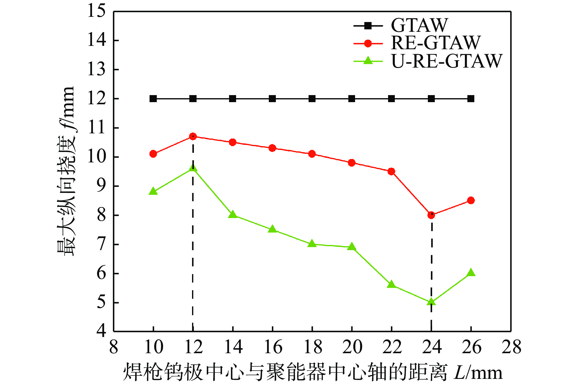
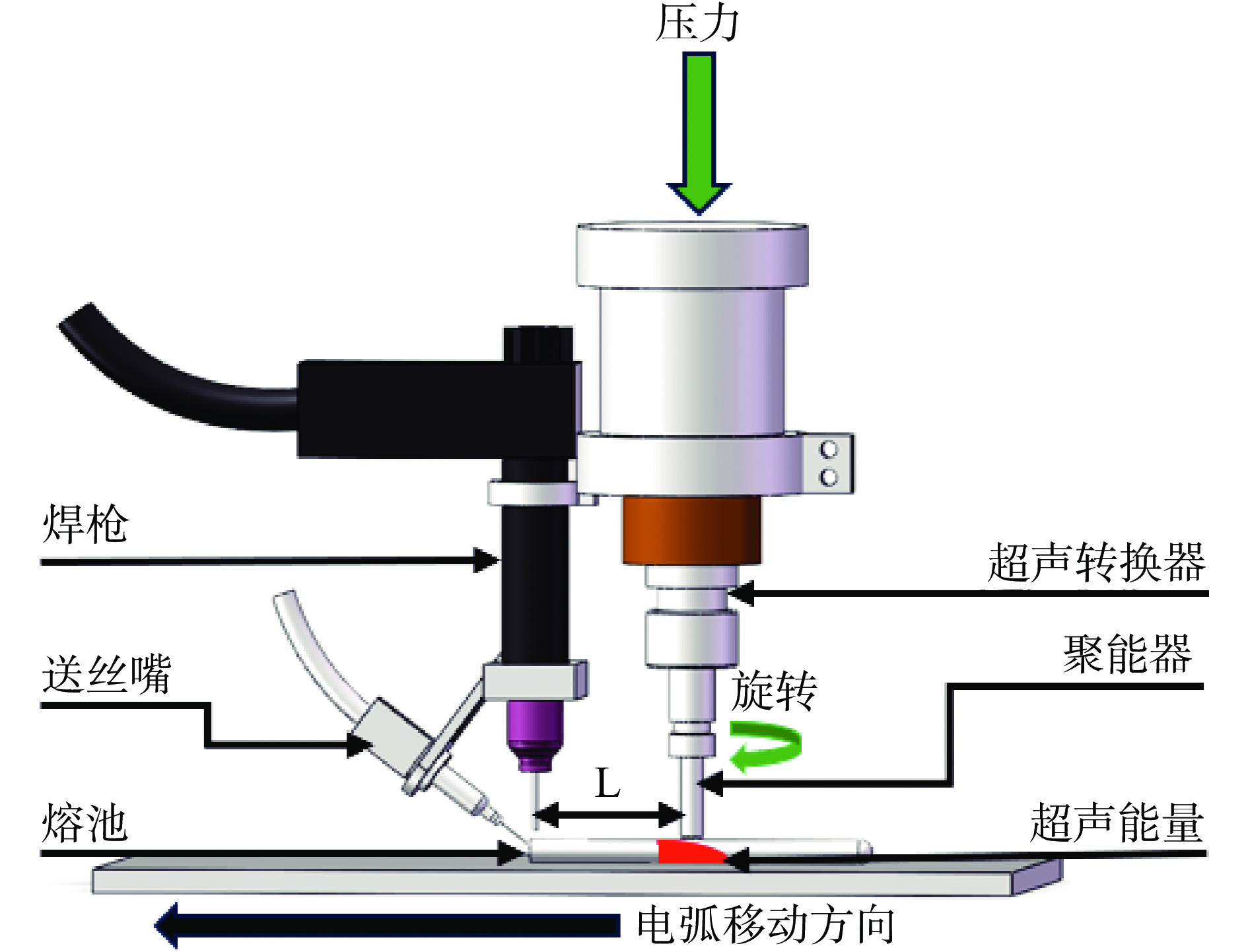
图 2 聚能器焊枪间距与焊接变形控制关系
Figure 2. Influence of the distance between the concentrator and the welding gun on the control of welding deformation
![]()
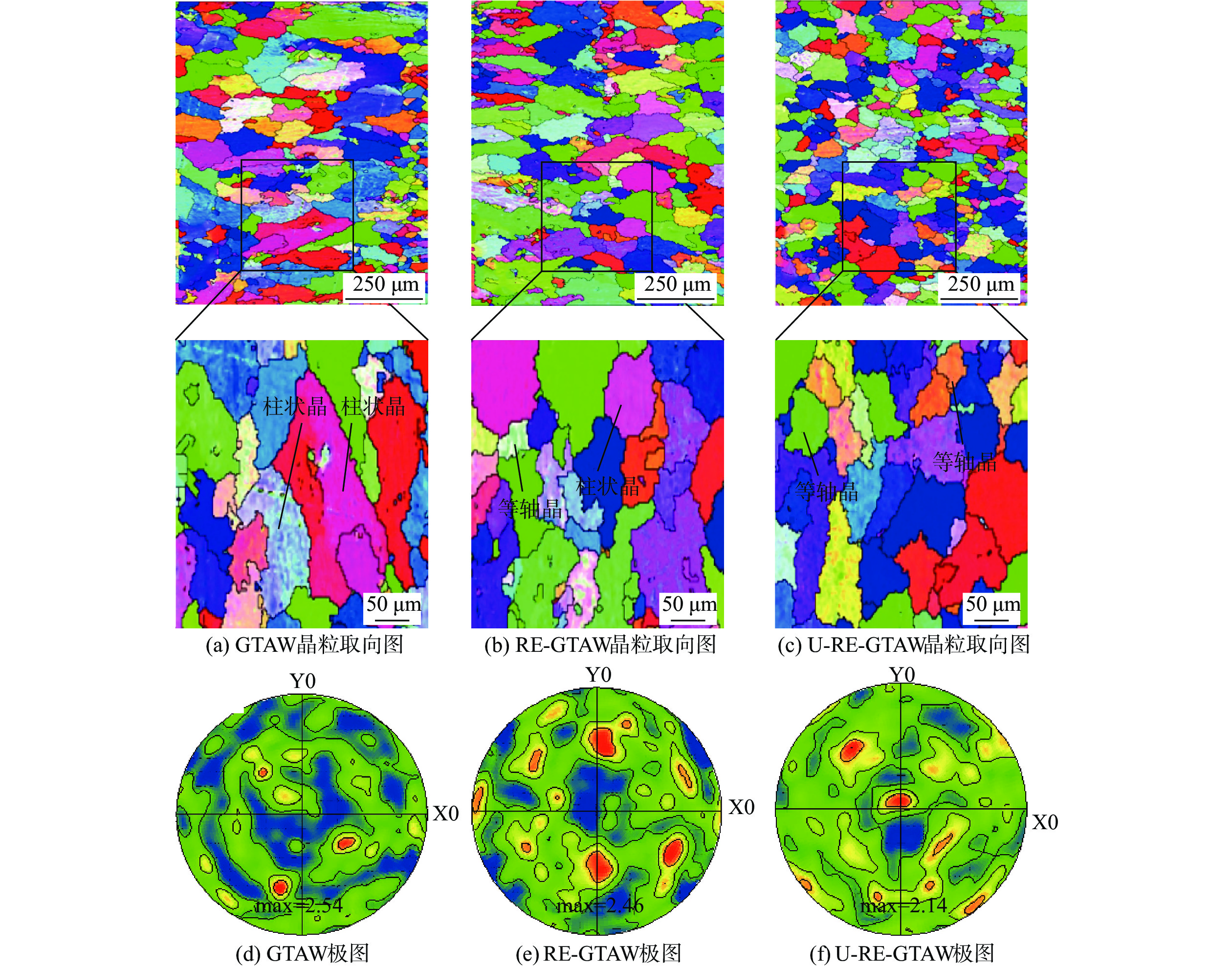
图 4 焊缝区晶粒IPF着色图、极图
Figure 4. Grain IPF and pole figure in the weld seam area. (a) grain orientation map of GTAW; (b) grain orientation map of RE-GTAW; (c) grain orientation map of U-RE-GTAW; (d) pole figure of GTAW; (e) pole figure of RE-GTAW; (f) pole figure of U-RE-GTAW
![]()
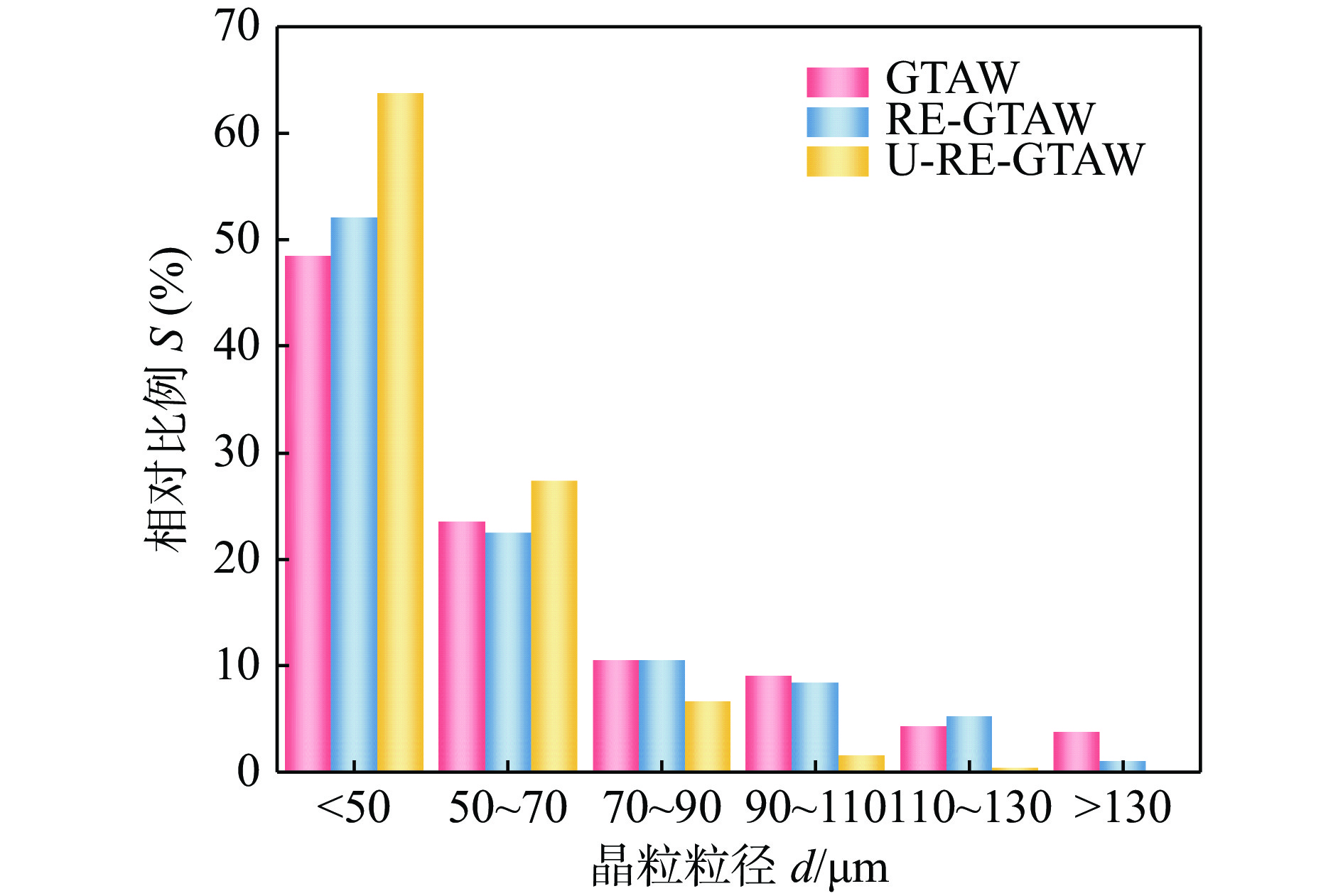
图 5 焊缝中心晶粒特征统计
Figure 5. Statistical analysis of grain characteristics at the center of the weld bead
![]()
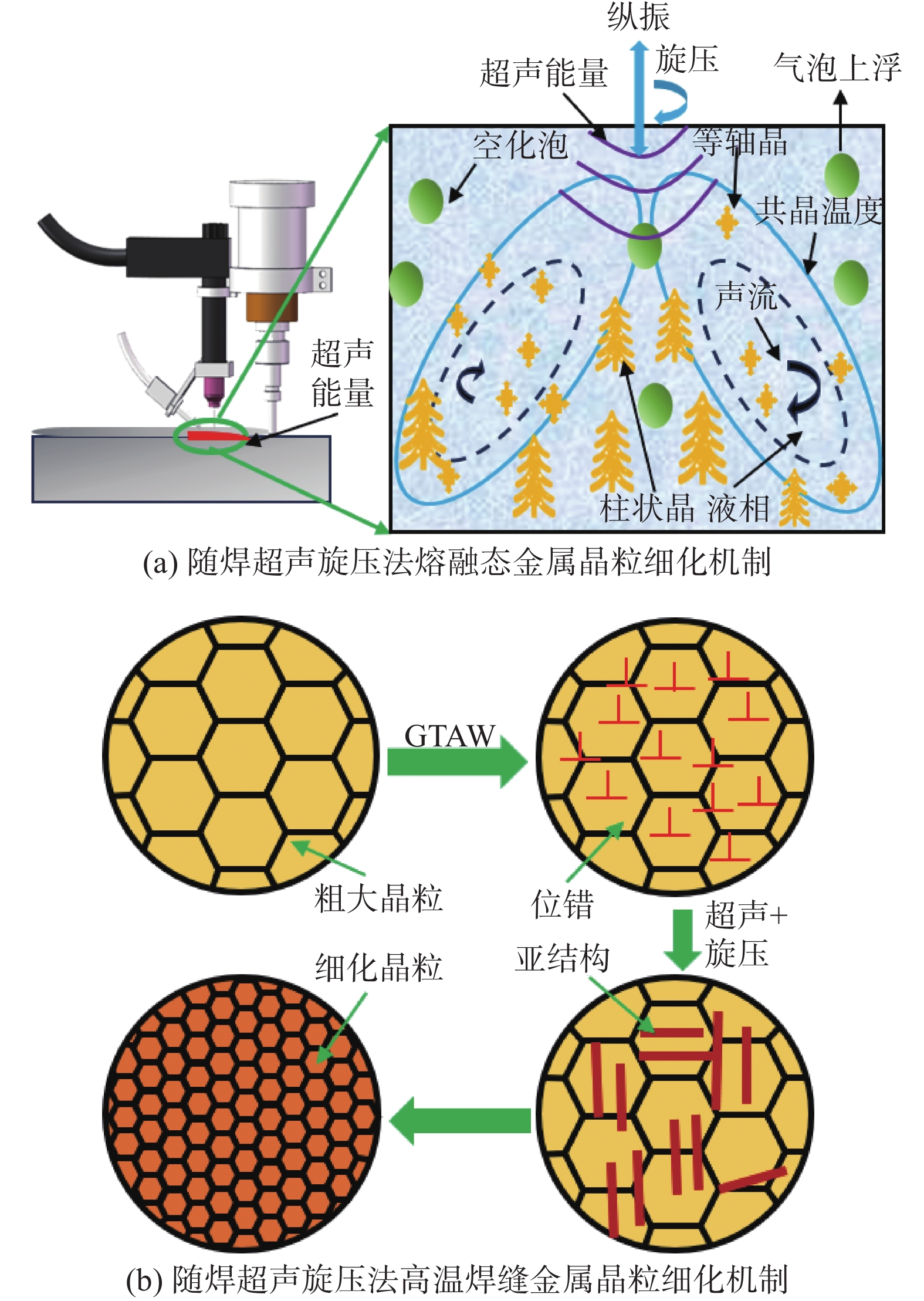
图 6 晶粒细化机制示意图
Figure 6. Schematic diagram of grain refinement mechanisms. (a) grain refinement mechanism of molten metal by welding with trailing ultrasonic rotating extrusion; (b) grain refinement mechanism of high-temperature weld metal by welding with trailing ultrasonic rotating extrusion
![]()
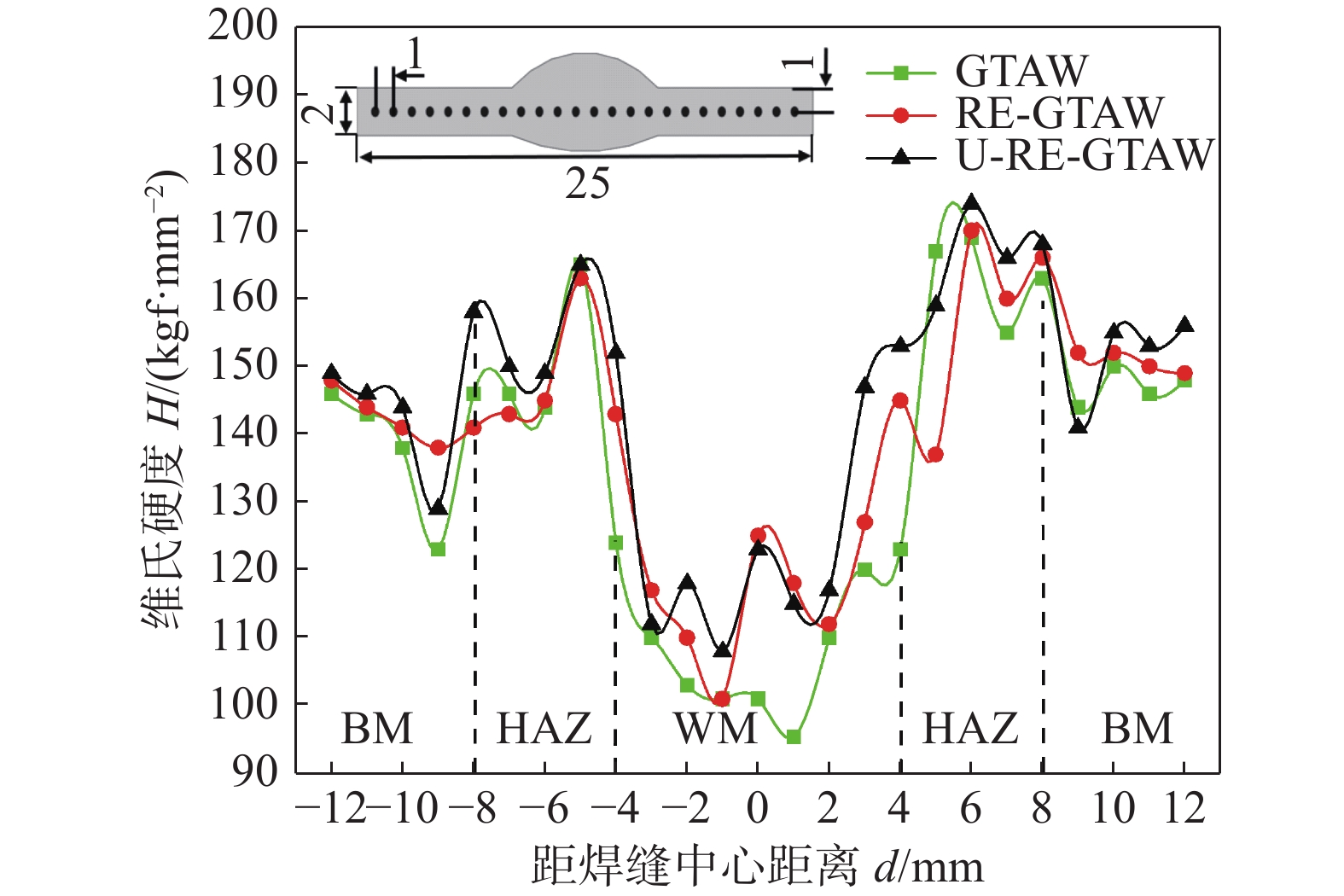
图 7 不同焊接工艺下焊接接头显微硬度(mm)
Figure 7. Welding joint microhardness under different welding processes
![]()
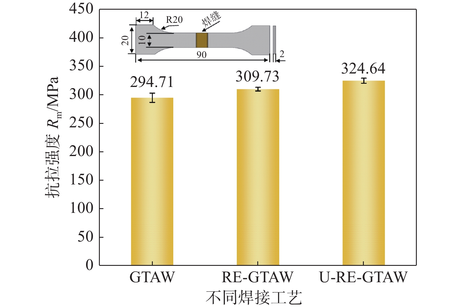
图 8 不同焊接工艺下焊接接头抗拉强度(mm)
Figure 8. Tensile strength of the welded joint under different welding processes
表 1 7075铝合金和ER5356焊丝化学成分(质量分数,%)
Table 1 Chemical compositions of 7075 aluminium and ER5356 welding wire
材料 Si Fe Cu Mn Mg Cr Zn Ti Al 7075-T6 ≤0.40 ≤0.50 1.50 ≤0.30 2.60 0.21 5.60 ≤0.20 余量 ER5356 0.25 0.40 0.10 0.10 5.00 0.10 0.10 0.15 余量  下载: 导出CSV
表 2 7075铝合金和ER5356焊丝力学性能
Table 2 Mechanical properties of 7075 aluminum alloy and ER5356 welding wire
材料 抗拉强度
Rm/MPa屈服强度
Rel/MPa断后伸长率
A(%)7075-T6 ≥540 ≥470 ≥7 ER5356 ≥250 ≥120 ≥10
下载: 导出CSV
表 3 焊接工艺参数
Table 3 Welding experiment parameters
焊接电流
I/A焊接速度
v/(mm·min−1)送丝速度
vs/(cm·min−1)气体流量
q/(L·min−1)聚能器直径
ϕ/mm聚能器旋转速度
vf/(r·min−1)超声振幅
AB/μm80 120 50 17 10 3 000 6
下载: 导出CSV
-
[1] Yan F, Wang X, Chai F, et al. Improvement of microstructure and performance for steel/Al welds produced by magnetic field assisted laser welding[J]. Optics and Laser Technology, 2019, 113: 164 − 170.
[2] Azarniya A, Taheri A K, Taheri K K. Recent advances in ageing of 7xxx series aluminum alloys: A physical metallur-gy perspective[J]. Journal of Alloys and Compounds, 2019, 781: 945 − 983.
[3] Sun Z, Zheng L, Yang H. Softening mechanism and micros tructure evolution of as extruded 7075 aluminum alloy during hot deformation[J]. Materials Characterization, 2014, 90: 71 − 80.
[4] Oropeza D, Hofmann D C, Williams K, et al. Welding and additive manufacturing with nanoparticle-enhanced aluminum 7075 wire[J]. Journal of Alloys and Compounds, 2020, 834: 154987.
[5] Dai W L. Effects of high intensity ultrasonic wave emission on the weldability of aluminum alloy 7075-T6[J]. Materials Letters, 2003, 57(16-17): 2447 − 2454.
[6] Li Z M, Zhu Y L, Du X K, et al. Microstructures and mechanical properties of 2024 aluminum alloy welded joint after ultrasonic peening treatment[J]. Rare Metal Materials and Engineering, 2012, 41: 307 − 311. doi: 10.1016/S1875-5372(12)60020-4
[7] Li J, Yang J G, Yan D J, et al. Rotating extrusion technique and its effect on quality of aluminum alloy thinplate weldments[J]. Transactions of Nonferrous Metals Society of China, 2010, 20(2): 183 − 188.
[8] 王鹏博. 7075铝合金超声辅助TIG焊接工艺及机理研究[D]. 沈阳:沈阳工业大学, 2019. Wang Pengbo. Research on ultrasonic assisted TIG welding process and mechanism of 7075 aluminum alloy [D]. Shenyang: Shenyang University of Technology, 2019.
[9] 李锐峰, 陈芙蓉. 超声功率对7075铝合金CMT焊接接头的组织与性能的影响[J]. 稀有金属材料与工程, 2023, 52(1): 274 − 282. doi: 10.12442/j.issn.1002-185X.20211105 Li Ruifeng, Chen Furong. The Influence of ultrasonic power on the microstructure and properties of 7075 aluminum alloy CMT welded joints[J]. Rare Metal Materials and Engineering, 2023, 52(1): 274 − 282. doi: 10.12442/j.issn.1002-185X.20211105
[10] Chen Q, Lin S, Yang C, et al. Effect of ultrasonic impact on the microstructure of welded joint of 2195 Al-Li alloy[J]. Acta Metallurgica Sinica English Letters, 2016, 29(4): 367 − 372.
[11] Chen Q, Ge H, Yang C, et al. Study on poresin ultrasonic-assisted TIG weld of aluminum alloy[J]. Metals, 2017, 7(2): 53.
[12] 李军, 杨建国, 翁路露, 等. 用旋转挤压方法控制薄板的焊接变形[J]. 焊接学报, 2008, 29(11): 25 − 28. doi: 10.3321/j.issn:0253-360X.2008.11.007 Li Jun, Yang Jianguo, Weng Lulu, et al. Control of welding deformation of thin plate by rotary compression method[J]. Transactionsof the China Welding Institution, 2008, 29(11): 25 − 28. doi: 10.3321/j.issn:0253-360X.2008.11.007
[13] 杨建国, 范成磊, 方洪渊. 随焊冲击碾压控制焊接应力变形新方法[J]. 机械工程学报, 2004(8): 87 − 90. Yang Jianguo, Fan Chenglei, Fang Hongyuan. A new method of controlling welding stress and deformation by welding impact Rolling[J]. Journal of Mechanical Engineering, 2004(8): 87 − 90.
[14] 刘雪松, 徐文立, 方洪渊. 钛合金薄板焊接应力的随焊锤击控制[J]. 焊接学报, 2004, 25(2): 84 − 86. Liu Xuesong, Xu Wenli, Fang Hongyuan. Control of welding stress in thin titanium alloy plates by welding hammer impact[J]. Transactionsof the China Welding Institution, 2004, 25(2): 84 − 86.
[15] Ma M, Lai R, Qin J, et al. Effect of weld reinforcement on tensile and fatigue properties of 5083 aluminum metal inert gas (MIG) welded joint: Experiments and numerical simulations[J]. International Journal of Fatigue, 2021, 144: 106046.
[16] Wang G, Li Q, Li Y, et al. Effects of weld reinforcement on tensile behavior and mechanical properties of 2219-T87 aluminum alloy TIG welded joints[J]. Transactions of Nonferrous Metals Society of China, 2017, 27(1): 10 − 16.
[17] Komarov S, Yamamoto T, Sun J. Fabrication of Al-Bi frozen emulsion alloys due to high intense ultrasound irradiation[J]. Journal of Alloys and Compounds, 2021, 859: 1582311.
[18] Liu X, Osawa Y, Takamori S, et al. Grain refinement of A-Z91 alloy by introducing ultrasonic vibration during solidifi-cation[J]. Materials Letters, 2008, 62(17): 2872 − 2875.
[19] Cai X, Lin S, Wang X, et al. Characteristics of periodic ult-rasonic assisted TIG welding for 2219 aluminum alloys[J]. Materials, 2019, 12(24): 11.
[20] Balasubramani N, Wang G, Stjohn D H, et al. Current understanding of the origin of equiaxed grains inpuremetals duri-ng ultrasonic solidification and a comparison of grain formation processes with low frequency vibration, pulsed magnetic and electric current pulse techniques[J]. Journal of Materi-als Science & Technology, 2021, 65: 38 − 53.
[21] Jamshidi R, Rossi D, Saffari N, et al. Investigation of the effect of ultrasound parameters on continuous sonocrystallization in a millifluidic device[J]. Crystal Growth & Design, 2016, 16(8): 4607 − 4619.
[22] Ashiri R, Niroumand B, Karimzadeh F. Physical, mechanical and dry sliding wear properties of an Al-Si-Mg-Ni-Cu allo-y under different processing conditions[J]. Journal of Alloys and Compounds, 2014, 582: 213 − 222.
[23] Wang J T, Chen J W, Zhang Y K, et al. Influence of ultra sonic impact treatment on stress corrosion of 7075 aluminum alloy and its welded joints[J]. Engineering Failure Analysis, 2023, 144: 106908.


计量
- 文章访问数: 40
- HTML全文浏览量: 3
- PDF下载量: 21
