
Effects of Si element on the weld formation and microstructure of titanium/steel dissimilar joints
-
摘要:
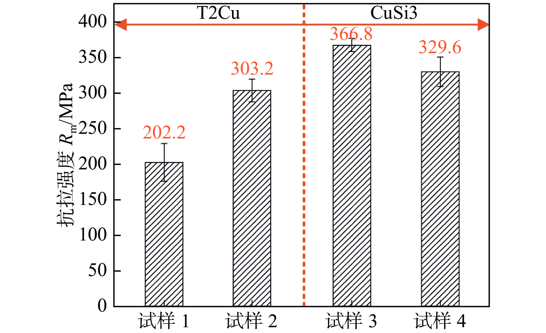
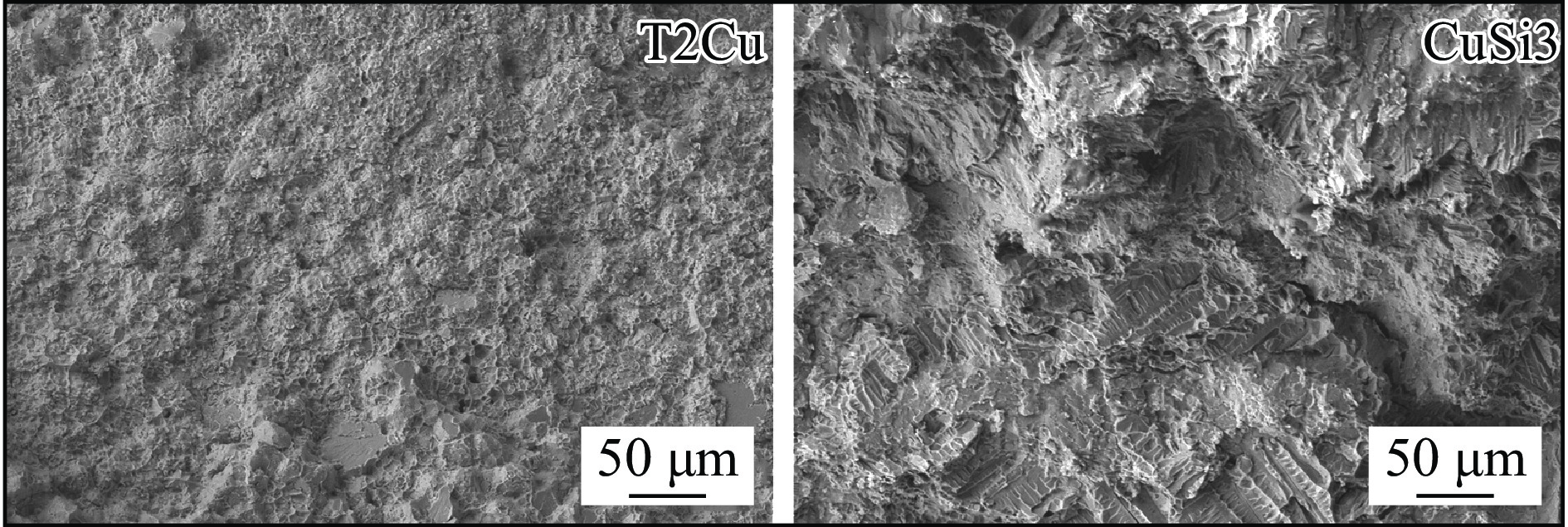
采用T2Cu和CuSi3焊丝在相同工艺参数下对厚度为1 mm的TC4钛合金及304不锈钢进行焊接,并借助光学显微镜(optical microscopy, OM)和扫描电镜(scanning electron microscopy, SEM)研究了两种焊丝下的TC4/304异种金属焊接熔池冶金行为. 对比分析了不同焊丝成分,尤其是Si元素的加入对TC4/304异种金属接头宏观成形、界面微观组织和力学性能的影响. 结果表明,Si元素的加入使液态熔池流动性显著增强,消除了凹陷和孔洞等缺陷,解决了焊缝背部熔合不良问题,焊缝宏观成形显著改善. 两种焊丝均有效阻隔了Ti,Fe原子,钛/铜界面未生成Ti-Fe化合物,但在焊缝中心以及铜/钢界面处生成了少量Ti-Fe相. CuSi3焊丝中充足的Si元素不仅使Ti5Si3相形核生长的更加充分,在熔池流动的作用下均匀分布于焊缝中,对接头起到弥散强化作用. 与T2Cu焊丝相比,CuSi3焊丝所得接头的抗拉强度提升了81.4%,最高达到366.8 MPa.
Abstract:Welding of 1mm thick TC4 titanium alloy and 304 stainless steel was performed using T2Cu and CuSi3 welding wires under the same process parameters. The metallurgical behavior of the TC4/304 dissimilar metal weld pool was studied using optical microscopy(OM) and scanning electron microscopy(SEM). A comparative analysis was conducted on the effects of different wire compositions, particularly the addition of silicon (Si), on the macro formation of the TC4/304 dissimilar metal joints, the microstructure at the interface, and the mechanical properties. The results showed that the addition of Si significantly enhanced the fluidity of the liquid weld pool, eliminated defects such as depressions and pores, and addressed issues of poor fusion at the back of the weld, leading to substantial improvements in macro formation of the welds. Both types of welding wires effectively hindered the diffusion of Ti and Fe atoms, preventing the formation of Ti-Fe compounds at the Ti/Cu interface, although a small amount of Ti-Fe phase was present at the center of the weld and at the Cu/Fe interface. The sufficient Si content in CuSi3 welding wire not only promoted more effective nucleation and growth of the Ti5Si3 phase but also allowed for its uniform distribution throughout the weld due to the flow of the weld pool, providing a dispersion strengthening effect for the joint. Compared to T2Cu welding wire, the joints obtained with CuSi3 welding wire exhibited a tensile strength increase of 81.4%, reaching a maximum of 366.8 MPa.
-
0. 序言
近年来,丝材电弧增材制造(wire arc additive manufacturing,WAAM)由于具有低成本、高效率和灵活性的优势正在成为制造大型金属部件的主流工艺[1-2]. 镍铝青铜 (nickel aluminum bronze,NAB) 合金具有低密度、高强度、高耐腐蚀性和高耐磨性,已经被广泛应用于船舶与海洋工程(如海水阀、泵和螺旋桨等)[3-4]. 25号钢是具有一定强度、硬度、塑性和韧性的优质碳素结构[5]. NAB/25号钢的双金属零件可以充分发挥两种金属的优点,被广泛应用于船体结构(如舵杆制动环)[6]. 然而,由于NAB和钢的热力学性能存在显著差异,增材制造NAB/钢具有一定的挑战性.
增材制造为多材料或混合零件的制造提供了一个新的可能[7]. 但是,使用电弧增材制造镍铝青铜/钢复合结构需要考虑以下问题. 首先,铜钢界面的凝固裂纹问题. 文献[8-9]表明,铜可以导致钢凝固过程中产生热裂纹,通过控制稀释率以确保熔合区的铜浓度大于52%时可以避免热裂纹的产生. 然而,稀释率在局部快速熔化和凝固的电弧增材制造过程中很难精确控制. 其次,铜和钢热膨胀系数的巨大差异会在界面处引入高残余应力,会导致界面开裂和分层[10]. 此外,残余应力会降低部件的疲劳寿命并导致几何精度下降[11-12].
为解决上述问题,将旁路分流熔化极惰性气体保护焊(bypass current metal inert gas welding,BC-MIG焊)应用在25号钢表面沉积镍铝青铜. 旁路耦合电弧可以降低电流密度,从而降低钢母材的热输入和稀释率,从而避免焊接裂纹. 此外,低的电弧热输入也可以降低接头内部的残余应力和变形. 在水中进行焊接提高冷却速率,这不仅可以减少层间冷却时间,提高焊接效率,而且可以避免在WAAM过程中由严重的热积累导致的成形质量差、尺寸精度低等问题.
为了探究一种可行的方法去制造可实际应用的NAB/钢复合结构件,提出了BC-MIG丝材电弧增材制造方法,同时整个过程在水冷条件下进行。在组件制备完成后,对组件进行了去热应力热处理,分析了热处理前后复合结构的焊缝成形、微观组织和力学性能.
1. 试验方法
试验所用板材为25号钢,尺寸为320 mm × 170 mm × 25 mm,直径为1.2 mm的镍铝青铜焊丝用于WAAM工艺,其化学成分如表1所示. 试验前先对25号钢板表面进行砂纸打磨,随后用酒精清洗板材表面. 焊接工艺参数如表2所示. 图1为BC-MIG电弧增材制造NAB/钢复合结构示意图. 为保证沉积表面平整性,采用往复沉积模式,沉积重叠率为50%. 采用BC-MIG焊来减少母材的热输入和稀释率,从而有效降低铜钢界面裂纹产生倾向和残余应力. MIG焊焊枪与基体成60º,TIG焊枪与基体成30º,并与MIG焊焊枪垂直,这有助于将旁路电弧热用于熔化焊丝而不是钢母材. 焊接过程中,流经焊丝的电流为MIG焊电流和TIG焊电流之和. 在水中进行焊接,为保证在钢表面全覆盖沉积,未用夹具压制,水面和沉积层表面高度差保持在2 mm,由于水冷速率较高,可以连续沉积.
表 1 25号钢和镍铝青铜焊丝的化学成分(质量分数,%)Table 1. Chemical compositions of 25 steel and NAB wire材料 C Si Mn Cr Ni Cu Al Zn Fe 25号钢 0. 25 0. 8 0. 3 0. 05 0. 05 0. 15 0. 1 0. 05 余量 NAB焊丝 — 0. 04 1. 0 — 4. 0 余量 8. 5 0. 003 3. 0 表 2 焊接工艺参数Table 2. Welding process parameters总电流
I/AMIG焊电流
Im /AMIG焊电压
U/V旁路TIG焊电流
It /A焊接速度
v/(m·min−1)气体流量Q/(L·min−1) MIG焊喷嘴高度
h/mm钨极高度
h2/mmMIG焊 TIG焊 200 160 21 40 0.7 15 5 8 5 ![]() 图 1 BC-MIG电弧增材制造NAB/钢复合结构示意图Figure 1. Schematic diagram of NAB/steel composite structures by BC-MIG WAAM
图 1 BC-MIG电弧增材制造NAB/钢复合结构示意图Figure 1. Schematic diagram of NAB/steel composite structures by BC-MIG WAAM在通过 WAAM 制造 NAB/钢复合结构后,对试样进行了去应力退火,退火工艺为在860 ℃保温3 h,随后炉冷至400 ℃,然后出炉空冷. 使用线切割垂直于界面和焊接方向对复合结构样品进行切割. 取焊缝中心的样品进行残余应力检测,通过Bruker D8 Discover型 X射线衍射仪(X-ray diffraction, XRD)测量了热处理前后试样相同位置的残余应力变化,测量参数见表3,测量位置如图2所示,铜侧和钢侧的测量点都在距NAB/钢界面1 mm处,相邻点间距为3 mm. 使用标准金相方法对横截面进行打磨和抛光,先用2%硝酸酒精溶液对25号钢腐蚀,然后用凯乐试剂对NAB侧腐蚀,腐蚀后通过Olympus DSX510型 3D超景深光学显微镜(optical microscope, OM)观察微观组织. 使用配备能量色散光谱仪(energy dispersive spectrometer,EDS)的Zeiss-Merlin Compact型扫描电子显微镜(scanning electron microscope,SEM)表征界面的微观结构和元素分布. 使用HMAS-D1000Z型维氏硬度测试仪对NAB/钢复合结构的界面硬度进行测量. 通过线切割制取了结构的水平和竖直方向的拉伸试样,试样尺寸如图2所示. 通过Instron 5967型万能试验机对NAB/钢复合结构力学性能进行测试.
表 3 残余应力测试参数Table 3. Residual stress test parameters测量方法 衍射晶面 辐射 X光管电压
U0 /kVX光管电流
Ix /mA扫描步
距α/(°)XRD Cu (311),
Fe (211)Crkα 20.0 5.0 0.1 ![]() 图 2 NAB/钢复合结构检测示意图 (mm)Figure 2. Schematic diagram of NAB/steel composite structure test. (a) horizontal tensile test; (b) vertical tensile test; (c) residual stress test
图 2 NAB/钢复合结构检测示意图 (mm)Figure 2. Schematic diagram of NAB/steel composite structure test. (a) horizontal tensile test; (b) vertical tensile test; (c) residual stress test2. 试验结果与分析
2.1 NAB/钢宏观形貌
图3为NAB/钢复合结构宏观形貌. 从图3a可以看出,沉积层表面平整没有发现明显的缺陷. 在整个沉积过程中,钢板在没有强制固定的情况下的自由变形较小,这归因于BC-MIG焊的低热输入,同时水冷降低了沉积过程的热积累. 图3c为NAB/钢在低倍显微镜下观察到的界面形貌,NAB/钢界面平整、连续、完好,没有气孔或裂纹等熔合缺陷.
![]() 图 3 NAB/钢复合结构宏观形貌Figure 3. Macroscopic morphology of NAB/steel composite structure. (a) frontal morphology; (b) side morphology; (c) interface morphology
图 3 NAB/钢复合结构宏观形貌Figure 3. Macroscopic morphology of NAB/steel composite structure. (a) frontal morphology; (b) side morphology; (c) interface morphology2.2 微观组织
图4为热处理前后的NAB微观组织形貌,可以看出富铜基体和基体内析出相的存在. 图4a为未热处理的NAB结构微观组织,铜基体周围分布了大量细小的κ相. 根据κ相凝固过程中形成的顺序(κI:1040 ℃,κII:930 ℃,κIII :820 ℃,κIV在进一步冷却期间)可知,这4个κ相的形态和分布不同,即它们的沉淀位置不同. 优先成核的玫瑰花状沉淀物(尺寸约为 5 ~ 10 µm)为κI,大小为 1 ~ 5 µm 的球状沉淀物被归类为κII,κIII呈层状形态,是β相在枝晶间区域共析分解的产物(α + κIII). 冷却过程中枝晶间区合金元素的偏析是形成κI,κII和κIII的主要原因. 此外,均匀沉淀的且非常细小(尺寸小于10 nm)的球状κIV沉淀物只有在高分辨率TEM检查中才能显示出来,在图4所示的光学显微照片中看不到. 图4b为热处理后的WAAM-NAB结构微观组织. 从图4b可以看出,热处理后析出相部分溶解,进入到富铜基体中形成固溶体. 此外,还有部分析出相在热处理过程中粗化,尺寸明显增大.
![]() 图 4 热处理前后的NAB微观组织Figure 4. Microstructure of NAB before and after heat treatment. (a) without heat treatment; (b) after heat treatment
图 4 热处理前后的NAB微观组织Figure 4. Microstructure of NAB before and after heat treatment. (a) without heat treatment; (b) after heat treatment图5为热处理前后的NAB/钢界面微观组织. 从图5a可以看出,NAB/钢界面没有发现明显的扩散层,这是由于水冷提高了NAB/钢的冷却速率,阻止了元素的相互扩散. 界面上方的NAB结构的析出相主要为κI,界面下侧的钢在高冷却速度下形成了针状马氏体. 从图5b可以看到明显的扩散层在NAB/钢界面,界面上方NAB结构的相主要为κI和κII,界面下侧的钢的晶粒尺寸增大,组织为白色的铁素体和灰黑色的片状珠光体.
![]() 图 5 热处理前后的NAB/钢界面微观组织Figure 5. Microstructure of NAB/steel interface before and after heat treatment. (a) without heat treatment; (b) after heat treatment
图 5 热处理前后的NAB/钢界面微观组织Figure 5. Microstructure of NAB/steel interface before and after heat treatment. (a) without heat treatment; (b) after heat treatment图6和图7分别为热处理前后NAB/钢界面的SEM形貌及EDS扫描结果,以进一步观察界面的冶金结合和相互扩散特性. 从图6a和图7a可以明显看到Cu,Fe,Al元素的相互扩散,Ni元素在界面的含量较低. Al元素偏聚在界面附近,但由于铝含量较低,界面没有明显的Fe-Al金属间化合物层,元素扩散层厚度约4 μm,主要为富铜相和富铁相. 从图6b和图7b可知,在热处理过程中,Fe,Al,Cu元素进一步相互扩散,导致扩散层明显变厚,接近17 μm.
![]() 图 6 热处理前后的NAB/钢界面SEM形貌Figure 6. SEM morphology of NAB/steel interface before and after heat treatment. (a) without heat treatment; (b) after heat treatment
图 6 热处理前后的NAB/钢界面SEM形貌Figure 6. SEM morphology of NAB/steel interface before and after heat treatment. (a) without heat treatment; (b) after heat treatment![]() 图 7 热处理前后的NAB/钢界面EDS扫描结果Figure 7. EDS scanning results of NAB/steel interface before and after heat treatment. (a) without heat treatment; (b) after heat treatment
图 7 热处理前后的NAB/钢界面EDS扫描结果Figure 7. EDS scanning results of NAB/steel interface before and after heat treatment. (a) without heat treatment; (b) after heat treatment为分析NAB在界面附近的元素分布和可能的相组成,观察了NAB的SEM形貌(在图5b界面上方50 μm处),如图8所示,并对图8进行了EDS面扫描和点扫描分析,其分析结果分别如图9和表4所示. 白色基体主要为Cu元素,也有Al和Fe固溶在Cu基体中形成固溶体,灰色相主要为Fe元素和Al元素,Ni含量较低且没有发现明显的偏聚. 通过对不同位置的灰色相进行元素含量分析可知,A,B,C,D点的Fe和Al原子摩尔比都接近3∶1,所以该处可能为Fe3Al相. E点主要为Cu元素,且Al元素含量较低,因此该处为富铜相.
位置 Cu Fe Al Ni 可能的相 A 7.71 70.17 18.17 2.15 Fe3Al B 12.36 63.08 21.09 2.01 Fe3Al C 12.68 62.68 20.43 2.44 Fe3Al D 8.24 68.35 18.50 2.29 Fe3Al E 79.55 4.01 14.03 1.75 富铜相 2.3 力学性能
2.3.1 残余应力
图10为热处理前后NAB/钢界面水平和竖直方向的残余应力. 钢水平和竖直方向的残余应力在−350 ~ −250 MPa之间,表现为压应力. 热处理后钢水平方向残余应力由压应力转为拉应力,且残余应力值降低到80 MPa以下. 钢竖直方向残余应力在热处理后方向未发生变化,但残余应力值降低到60 MPa以下. NAB侧残余应力分布差异较大,水平方向残余应力在−450 ~ −120 MPa之间,竖直方向残余应力在−550 ~ 90 MPa之间,这是由于在WAAM过程中NAB受到周期性、非稳态的热循环,同时冷却速率较高,导致结构件存在较大且分布不均匀的残余应力. 热处理后残余应力分布均匀,且明显下降至120 MPa以下. 在热处理过程中,试样的晶粒尺寸增大,大尺寸的晶粒和少量的晶界导致位错更容易滑移和攀升,从而降低位错密度. 使用Zener-Wert-Avrami 函数定义残余应力松弛过程[13].
![]() 图 10 NAB/钢复合结构在水平和竖直方向的残余应力Figure 10. Residual stresses in the horizontal and vertical directions of the NAB/steel composite structure. (a) horizontal direction of steel; (b) vertical direction of steel; (c) horizontal direction of NAB; (d) vertical direction of NAB
图 10 NAB/钢复合结构在水平和竖直方向的残余应力Figure 10. Residual stresses in the horizontal and vertical directions of the NAB/steel composite structure. (a) horizontal direction of steel; (b) vertical direction of steel; (c) horizontal direction of NAB; (d) vertical direction of NAB$$ \frac{{\sigma }^{{\rm{RS}}}}{{\sigma }_{0}^{{\rm{RS}}}}=\exp[-\left(A{t}_{0}{)}^{m}\right] $$ (1) $$ A=B\exp\left[-\frac{\Delta H}{k{T}_{0}}\right] $$ (2) 式中:
$ {\sigma }_{0}^{{\rm{RS}}} $ 为初始残余应力;$ {\sigma }^{{\rm{RS}}} $ 为在热处理后的残余应力;$ {t}_{0} $ 为热处理时间;m为反应应力松弛的数值参数;B为常数;k为玻尔兹曼常数;T0为热处理温度;$ \Delta H $ 为应力松弛过程的活化焓.$ {\sigma }_{0}^{{\rm{RS}}} $ 和$ {t}_{0} $ 均为固定值. 因此,热处理后的残余应力$ {\sigma }^{{\rm{RS}}} $ 主要与$ {T}_{0} $ 有关,即$ {\sigma }^{{\rm{RS}}} $ 随着热处理温度的升高而降低直到$ {T}_{0} $ 达到阈值. 材料中残余应力的消除或松弛可以改善材料强度和抗疲劳等力学行为,从而延长使用寿命.2.3.2 抗拉强度
沿不同方向拉伸时,热处理前后NAB/钢结构拉伸性能的影响如图11所示,热处理前NAB/钢水平方向的抗拉强度和断后伸长率分别为450 MPa和40.0%,竖直方向的抗拉强度分别为424 MPa和45.0%. 热处理后,NAB/钢结构水平方向的抗拉强度为430 MPa,但断后伸长率为60.0%,竖直方向的抗拉强度为415 MPa,但断后伸长率为55.0%. 强度略微降低是由于热处理降低了结构的位错密度.
![]() 图 11 热处理前后NAB/钢结构的拉伸性能Figure 11. Tensile property of NAB/steel structure before and after heat treatment. (a) horizontal direction; (b) vertical direction
图 11 热处理前后NAB/钢结构的拉伸性能Figure 11. Tensile property of NAB/steel structure before and after heat treatment. (a) horizontal direction; (b) vertical direction2.3.3 硬度
使用加载载荷1.96 N对热处理前后的NAB/钢界面进行显微硬度测量,每个点间距200 μm,界面附近点间距100 μm,界面的显微硬度分布如图12 所示. 从图12可以看出,钢在界面附近的硬度较高,在第一层沉积过程中钢经历了电弧的高热输入和水冷的高冷却速率,相当于进行了一次淬火,而后续沉积层的热输入对在水中的钢影响较小,导致钢在界面附近硬度略微提高. 而在下一层NAB沉积过程中的热输入相当于对前一层NAB进行了一次热处理,因此界面附近NAB硬度没有明显提高. 扩散层的硬度在钢和NAB之间,表明堆焊期间未生成金属间化合物层,主要是富铁相和富铝相. 这也表明扩散层的延展性大于不锈钢,主要是由铜的渗透和分解进入扩散层所致(图5).
3. 结论
(1) 使用BC-MIG丝材电弧增材制造技术实现了NAB和25号钢的良好冶金结合. 由于旁路分流和水冷降低了沉积过程的热输入和热积累,结构自由变形较小,且混合界面没有任何熔合缺陷和裂纹.
(2) 水冷条件下,NAB/钢界面元素扩散层仅为4 μm,热处理后扩散厚度变为17 μm. 热处理前后的界面都没有明显的金属间化合物层.
(3) 水冷条件下,界面附近钢侧的残余应力变化较小,而铜侧残余应力分布差异较大. 热处理后残余应力明显下降,结构的抗拉强度和断后伸长率明显提高,而硬度略微下降,主要归因于位错密度降低由于位错在高温下的滑移和攀升.
-
![]()
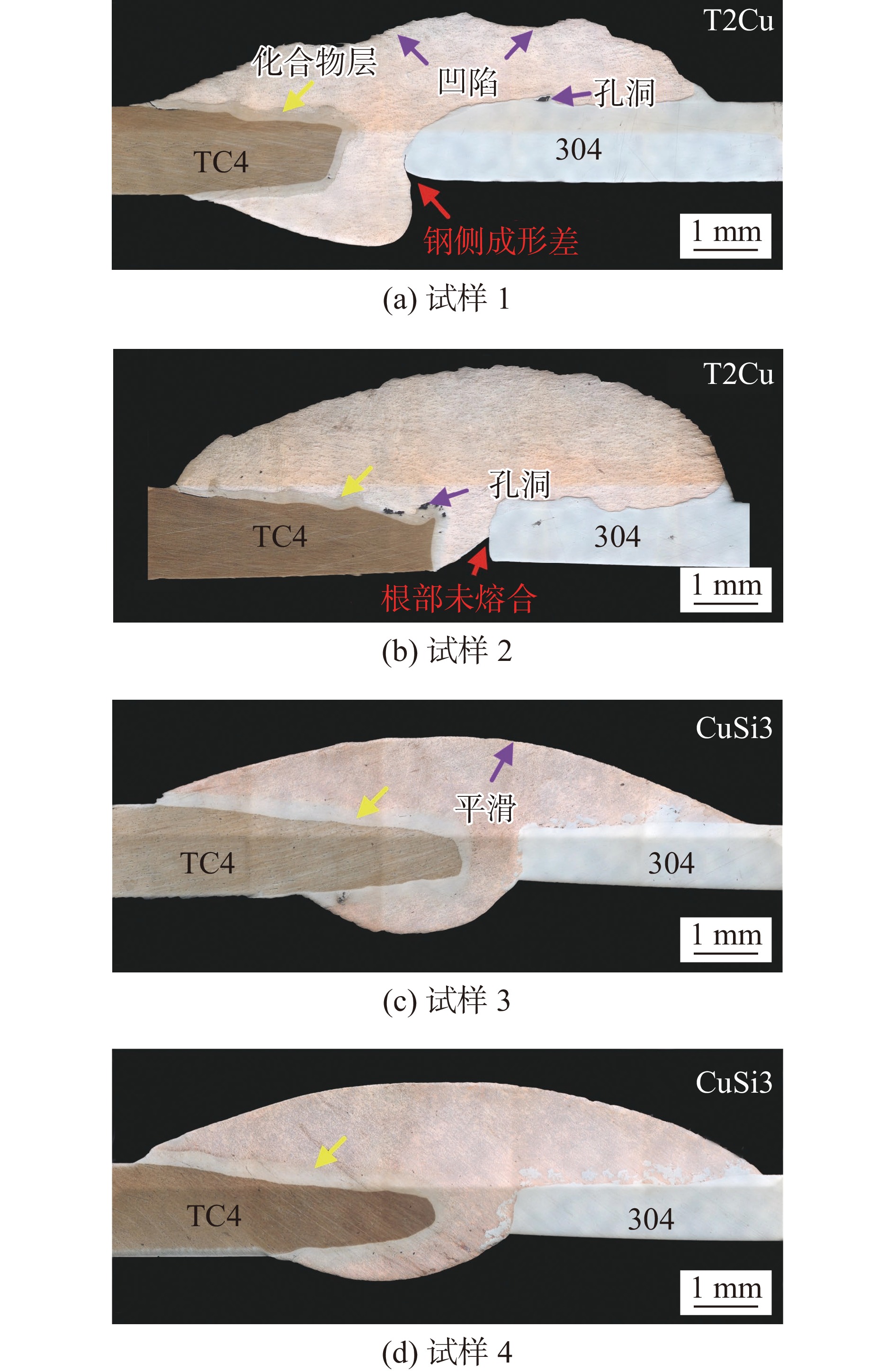
图 2 不同填充焊丝下焊缝宏观截面成形
Figure 2. Cross-sectional morphologies of weld joints obtained by different filler wires. (a) specimen 1; (b) specimen 2; (c) specimen 3; (d) specimen 4
![]()
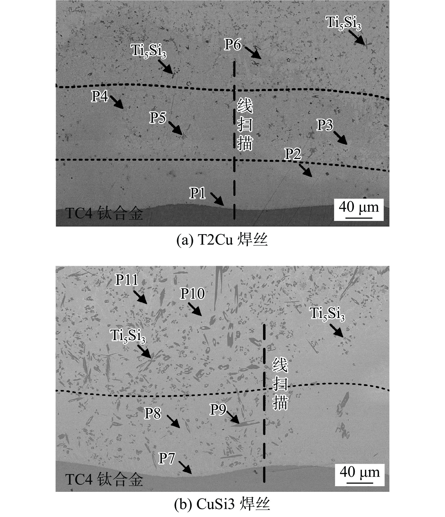
图 3 不同填充焊丝下的钛/铜界面微观结构
Figure 3. Microstructure of Ti/Cu interface for different filler wires. (a) T2Cu welding wire; (b) CuSi3 welding wire
![]()
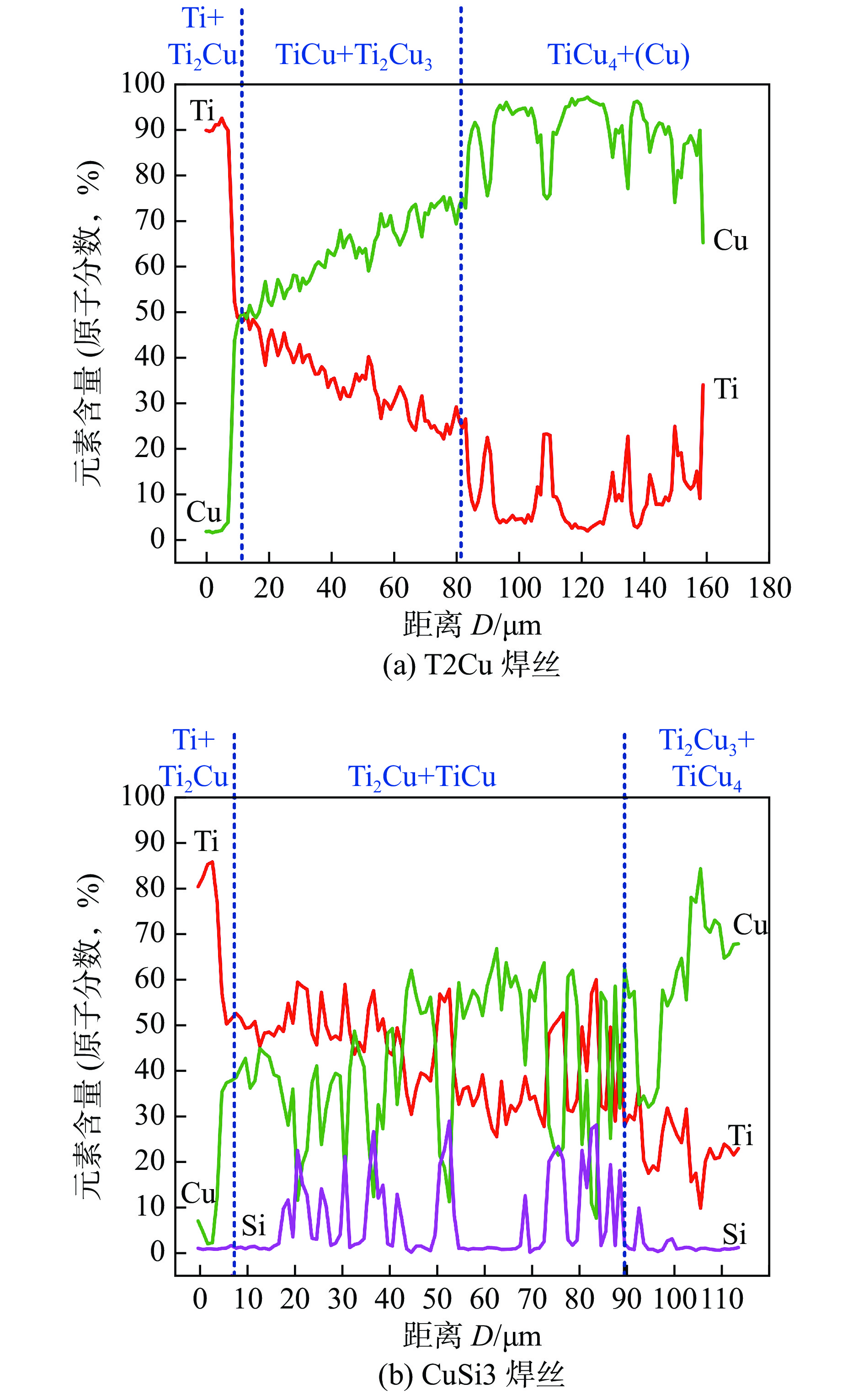
图 4 不同填充焊丝下的钛/铜界面线扫描分布结果
Figure 4. EDS line scanning results of Ti/Cu interface for different filler wires. (a) T2Cu welding wire; (b) CuSi3 welding wire
![]()
图 5 不同填充焊丝下的焊缝中心微观结构
Figure 5. Microstructure of weld seam for different filler wires. (a) T2Cu welding wire; (b) CuSi3 welding wire
![]()
图 6 铜/钢界面结构以及能谱面扫描结果
Figure 6. Microstructure and EDS mapping results of Cu/steel interface. (a) T2Cu welding wire; (b) CuSi3 welding wire
表 1 母材的元素成分 (质量分数,%)
Table 1 Base material compositions
材料 Cr Ni Al V Cu Si Fe Ti TC4 — — 5.6 ~ 5.8 3.5 ~ 4.5 0.3 — — 余量 304 18 ~ 20 8 ~ 11 — — 0.15 0.1 余量 0.15  下载: 导出CSV
表 2 焊丝的元素成分 (质量分数,%)
Table 2 Welding wire compositions
材料 Fe Al Si Cu T2Cu — — 0.3 余量 CuSi3 0.3 0.01 2.8 ~ 4.0 余量
下载: 导出CSV
表 3 焊接过程工艺参数
Table 3 Parameters and details of welding process
试样 焊接电流
I/A焊接电压
U/V焊接速度
v/(mm·s−1)热输入
H/(J·mm−1)送丝速度
vw/(m·min−1)焊丝 1 65 9.6 8 66.3 3.2 T2Cu 2 65 9.6 6 88.4 3.2 T2Cu 3 65 9.6 8 66.3 3.2 CuSi3 4 65 9.6 6 88.4 3.2 CuSi3
下载: 导出CSV
表 4 钛侧界面点扫描分析结果
Table 4 EDS spots results of Ti/Cu interfaces
位置 元素含量(原子分数,%) 可能的相 Ti Cu Fe Al Si P1 82.09 10.65 1.31 5.94 — Ti + Ti2Cu P2 38.79 50.68 1.97 8.56 — TiCu P3 15.23 79.21 2.31 3.22 — TiCu4 P4 28.02 66.17 1.00 4.80 — Ti2Cu3 + TiCu4 P5 50.39 9.59 — 1.02 34.89 Ti5Si3 P6 17.58 80.37 — 2.05 — TiCu4 P7 52.24 35.77 4.07 7.91 — TiCu + Ti2Cu P8 41.73 49.11 3.90 5.26 — TiCu P9 54.02 9.42 — — 36.56 Ti5Si3 P10 20.10 79.90 — — — TiCu4 P11 12.13 87.87 — — — TiCu4 + (Cu)
下载: 导出CSV
表 5 焊缝中心及铜/钢界面点扫描分析结果
Table 5 EDS spots results of weld seams and Cu/steel interfaces
位置 元素(原子分数,%) 可能的相 Ti Cu Fe Cr Si P1 37.20 49.30 6.70 — 5.10 Ti2Cu3 P2 30.53 10.43 41.44 — 17.60 TiFe2 + Ti5Si3 P3 54.02 — — — 36.56 Ti5Si3 P4 33.61 10.61 26.83 — 23.76 TiFe2 + Ti5Si3
下载: 导出CSV
表 6 铜/钢界面点扫描分析结果
Table 6 EDS spots results of Cu/steel interfaces
位置 元素(原子分数,%) 可能的相 Ti Cu Fe Cr Si P5 25.09 4.30 51.49 11.51 7.58 TiFe2 + (Fe) P6 25.71 4.13 51.20 11.70 7.30 TiFe2 + (Fe) P7 3.75 4.22 67.88 19.54 — (Fe)
下载: 导出CSV
-
[1] 毕志雄, 李雪交, 吴勇, 等. 钛箔/钢爆炸焊接的界面结合性能[J]. 焊接学报, 2022, 43(4): 81 − 85. doi: 10.12073/j.hjxb.20211105002 Bi Zhixiong, Li Xuejiao, Wu Yong, et al. Interfacial bonding properties of titanium foil/steel explosive welding[J]. Transactions of the China Welding Institution, 2022, 43(4): 81 − 85. doi: 10.12073/j.hjxb.20211105002
[2] Shi C G, Sun Z R, Fang Z H, et al. Design and test of a protective structure for the double vertical explosive welding of large titanium/steel plate[J]. China Welding, 2019, 28(3): 7 − 14.
[3] 胡奉雅, 许国敬, 陈伟, 等. 钛/钢复合板焊接技术研究现状及发展趋势[J]. 焊接学报, 2021, 42(6): 30 − 43. Hu Fengya, Xu Guojing, Chen Wei, et al. Research status and development trend of titanium/steel bimetallic composite plates of welding[J]. Transactions of the China Welding Institution, 2021, 42(6): 30 − 43.
[4] Chu Q L, Tong X W, Xu S, et al. The formation of intermetallics in Ti/steel dissimilar joints welded by Cu-Nb composite filler[J]. Journal of Alloys and Compounds, 2020, 828: 154389. doi: 10.1016/j.jallcom.2020.154389
[5] Ren G Z, Zhang Y, Zhou J P, et al. Titanium/steel composites were prepared by composite interlayer and two pass laser welding[J]. Journal of Materials Research and Technology, 2023, 27: 6367 − 6375. doi: 10.1016/j.jmrt.2023.11.118
[6] Hao X H, Wei X L, Li S H, et al. Joining mechanism evolution of fusion welded TC4 titanium alloy/304 stainless steel dissimilar joint by GTAW[J]. Science and Technology of Welding and Joining, 2023, 28(9): 1031 − 1040. doi: 10.1080/13621718.2023.2264572
[7] Zhang Y, Chen Y K, Zhou J P, et al. Experimental and numerical study on microstructure and mechanical properties for laser welding-brazing of TC4 titanium alloy and 304 stainless steel with Cu-base filler metal[J]. Journal of Materials Research and Technology, 2020, 9(1): 465 − 477. doi: 10.1016/j.jmrt.2019.10.075
[8] Li J Z, Liu Y B, Zhen Z Y, et al. Weld formation mechanism and microstructural evolution of TC4/304 stainless steel joint with Cu-based filler wire and preheating[J]. Materials, 2019, 12(19): 3071. doi: 10.3390/ma12193071
[9] Jin P, Liu Y B, Sun Q J, et al. Wetting mechanism and microstructure evolution of TC4/304 stainless steel joined by CMT with an assisted hybrid magnetic field[J]. Journal of Alloys and Compounds, 2020, 819: 152951. doi: 10.1016/j.jallcom.2019.152951
[10] Chang J H, Cao R, Yan Y J. The joining behavior of titanium and Q235 steel joined by cold metal transfer joining technology[J]. Materials, 2019, 12(15): 2413. doi: 10.3390/ma12152413
[11] Mou G, Hua X M, Wang M, et al. Effect of axial magnetic field on cold metal transfer arc-brazing of Ti6Al4V to 304L steel[J]. Journal of Materials Processing Technology, 2020, 275: 116322. doi: 10.1016/j.jmatprotec.2019.116322
[12] Cheng Z, Huang J H, Ye Z, et al. Butt brazing of titanium alloys/stainless steel plates by MIG-TIG double-sided arc welding process with copper filler metal[J]. Journal of Materials Research and Technology, 2019, 8(1): 1566 − 1570. doi: 10.1016/j.jmrt.2018.06.009
[13] Hao X H, Dong H G, Li P, et al. Dissimilar joining of TC4 alloy to ST16 steel by GTAW[J]. Journal of Manufacturing Processes, 2019, 37: 413 − 417. doi: 10.1016/j.jmapro.2018.12.016
[14] 陈夏明, 王晓南, 董其鹏, 等. 焊丝Si含量对铝合金激光-CMT复合焊接头组织性能的影响[J]. 中国激光, 2021, 48(22): 30 − 38. Chen Xiaming, Wang Xiaonan, Dong Qipeng, et al. Effect of filling material with different Si content on microstructure and properties of laser-CMT aluminum alloy joints[J]. Chinese Journal of Lasers, 2021, 48(22): 30 − 38.
[15] Hu Y, Shi Y H, Sun K, et al. Effect of filler Si content on the microstructure and properties of underwater hyperbaric welded duplex stainless steel[J]. Journal of Materials Processing Technology, 2020, 279: 116548.
-
期刊类型引用(2)
1. 刘缙,王克鸿,徐程,刘晨雨,彭勇. 电弧增材镍铝青铜的组织与性能. 焊接学报. 2024(08): 103-109 .  本站查看
本站查看
2. 马景平,曹睿,周鑫. 高强钢焊接接头疲劳寿命的提高方法进展. 焊接学报. 2024(10): 115-128 . 本站查看
其他类型引用(0)


计量
- 文章访问数: 185
- HTML全文浏览量: 40
- PDF下载量: 45
- 被引次数: 2
