
Laser filling welding repair process for U-shaped groove of S32101 duplex stainless steel
-
摘要:
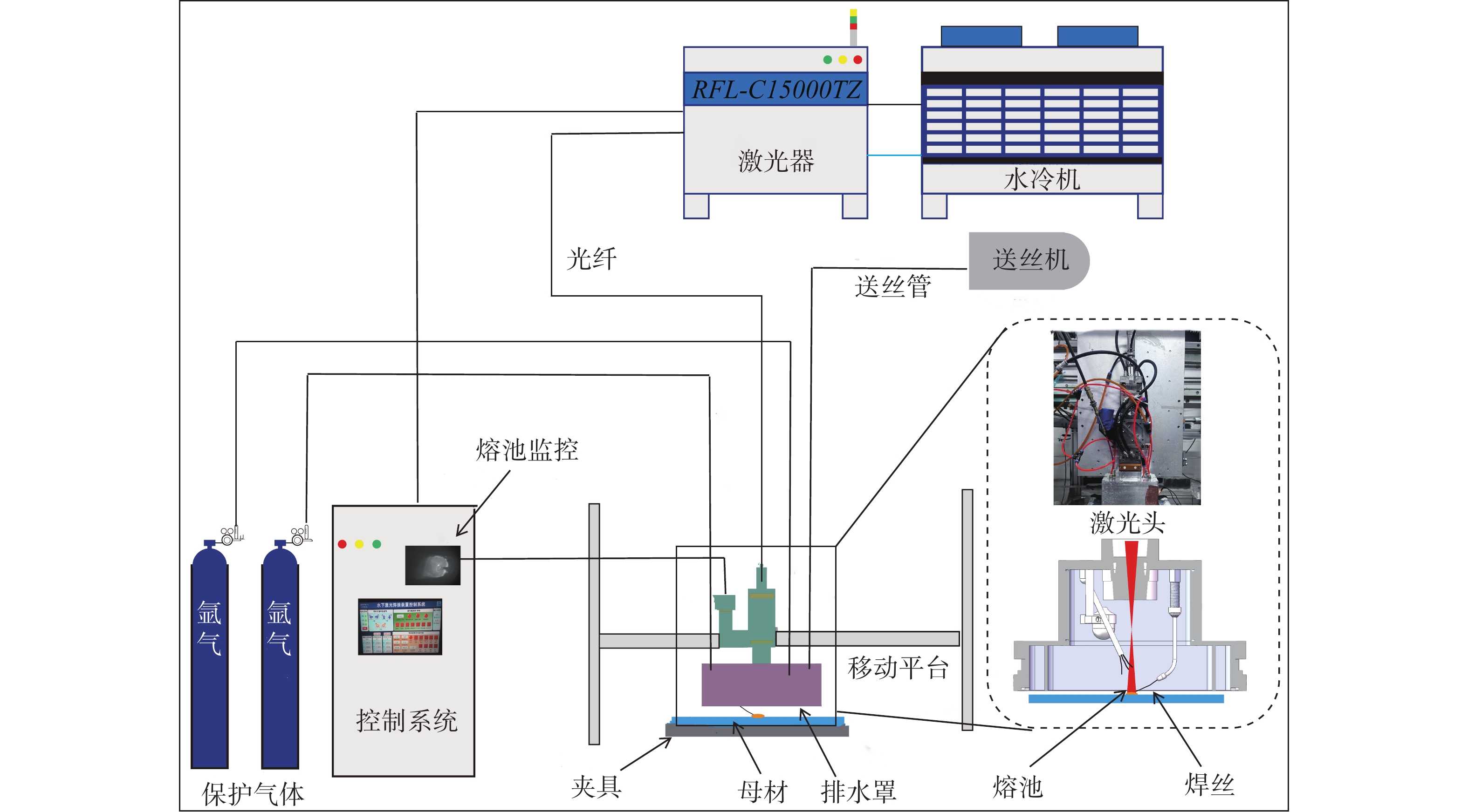
文中采用开设坡口的方式去除裂纹、通过坡口填充焊接修复的方式进行维修,在空气环境中开展了S32101双相不锈钢激光填丝焊接修复工艺试验研究,焊接工艺及相关参数可以作为水下焊接研究的参考依据. 为避免过高激光功率输入损坏焊接辅助装置,在
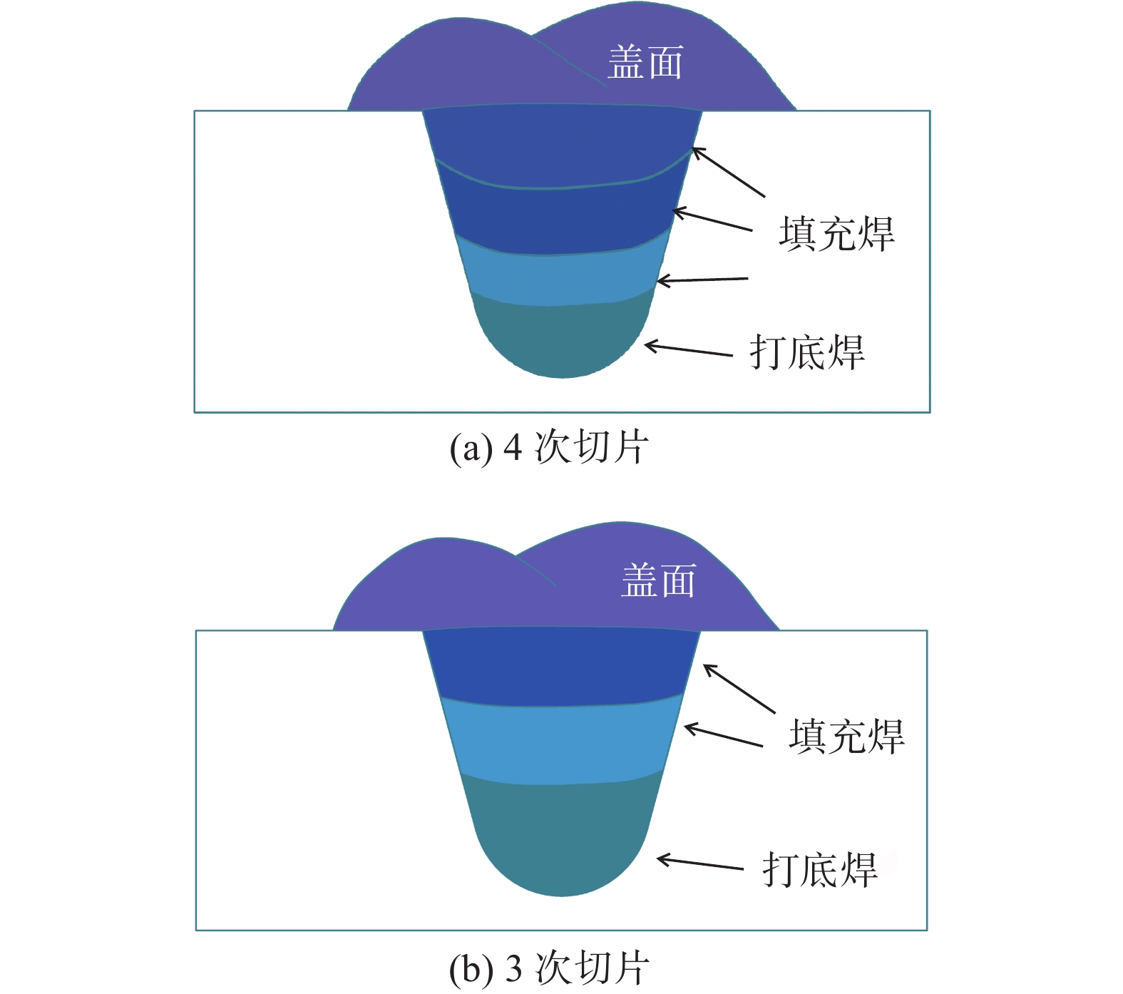
5000 ~6000 W激光功率的工艺窗口下,对开设的坡口进行了3次填充修复及4次填充修复,对焊缝截面、显微组织、力学性能以及耐腐蚀性能分别进行了研究. 在试验过程中,采用了光学显微镜和扫描电镜等,分析了焊接过程中热输入对微观组织转变的影响. 同时通过对比不同激光功率下焊缝的拉伸性能和显微硬度,进一步揭示了工艺参数对焊缝力学性能和耐腐蚀性能的具体影响,从而优化了修复工艺的稳定性和可靠性. 结果表明,3次填充修复后的焊缝存在气孔以及冶金熔合不良等问题,4次填充修复后的焊缝截面未见气孔缺陷,拉伸试件断在母材位置. 层间焊道的预热和再热促使焊缝中奥氏体析出,焊缝中奥氏体含量略高于铁素体含量,平均硬度略低于母材. 焊缝中较高含量的Ni元素和Mo元素使得焊缝的耐腐蚀性能优于母材,4次填充修复得到的焊缝满足空气环境中修复质量标准要求.-
关键词:
- 激光焊接 /
- S32101双相不锈钢 /
- 微观组织 /
- 耐腐蚀性能 /
- 显微硬度
Abstract:In this paper, cracks were removed by beveling, and repairs were performed using groove-filling welding techniques. An experimental investigation of laser wire-filling welding repair of S32101 duplex stainless steel in an air environment was conducted. The welding procedure and related parameters may serve as a reference for underwater welding studies. To prevent damage to the welding auxiliary equipment caused by excessive laser power input, comparative experiments were performed with three filling repairs and four filling repairs under a process window of
5000 ~6000 W laser power. The cross-sections, microstructure, mechanical properties, and corrosion resistance of the welds were thoroughly analyzed. During the experiments, optical microscopy and scanning electron microscopy were used to examine the effects of heat input during welding on microstructural transformations. Additionally, by comparing the tensile properties and microhardness of welds at different laser power levels, the specific influence of process parameters on the mechanical properties and corrosion resistance of the welds was further elucidated, thereby optimizing the stability and reliability of the repair process. The results showed that the welds repaired with three filling repairs exhibited issues such as porosity and poor metallurgical fusion, whereas the cross-sections of the welds repaired with four filling repairs showed no porosity defects, and the tensile specimens fractured at the base metal. Preheating and reheating of the interpass welding promoted the precipitation of austenite in the welds, and the austenite content was slightly higher than that of ferrite, with the average hardness being slightly lower than that of the base metal. The higher Ni and Mo content in the welds contributed to superior corrosion resistance compared to the base metal. The welds repaired with four filling repairs met the quality standards for repairs conducted in an air environment. -
0. 序言
随着航空制造业的发展,大型整体结构件逐渐替代了部分螺栓连接或铆接的装配件. 该类结构一般为主要承力构件,对力学性能要求较高,构件的整体化可以大幅度降低装配工作量,减重10%~30%,同时具有较好的密封性,成为近年来航空零件设计的发展趋势[1-3].
工业中制造这类构件主要有整体加工、增材制造和分段组合等3种方法[4-5],整体加工需要先通过锻造或轧制加工出整体毛坯,再机械加工成最终零件,其毛坯锻造质量控制和复杂的加工变形问题已经成为研制与生产的障碍[6-9]. 同时该方法成本高,加工周期长;采用增材制造方法制备的零件力学性能控制技术难度大,存在“热应力”控制问题[4],目前国内只有少数几家单位突破了大型整体主承力构件的激光增材制造技术,同时成本较高;采用分段组合方法,周期短、成本低[5],但是常用的熔焊拼接方法存在一些问题,比如潜弧焊存在合格率低、变形大、尺寸控制难等问题[10]. 线性摩擦焊方法进行组合连接具有力学性能优异,焊接变形小等明显优势.
目前的线性摩擦焊通常进行对接焊接,受设备限制,要求振动侧不能超重、超长. 文中提出了一种将线性摩擦焊用于长形构件分段焊接组合的方法[11],先分段制造长形构件的几个部分,在两个分段的待连接处,加工成相对的斜坡,与楔块的角度相同,振动楔块体积、重量小,可实现超长形构件的任意位置焊接. 楔形的接头形式可以较好的承受焊接过程中的摩擦压力,无需从两端施加轴向压力,从而在目前的通用设备上实现了长形构件的拼接. 线性摩擦焊接头具有优异的力学性能、接头热输入量和变形量小等优势,但是采用楔块焊接其焊缝不再是通常的平面,而是V形形式,焊缝界面与焊接压力之间的夹角不再是通常情况下的90°,由此带来了特有的金属流动规律与焊接缺陷产生. 文中研究嵌入式线性摩擦焊过程金属流动规律及其影响因素,分析焊接缺陷产生原因和控制方法,为长形钛合金承力结构件的线性摩擦焊提供技术基础.
1. 试验方法
选用的TC17钛合金为α-β型钛合金,广泛用于制造发动机叶盘及飞机结构中的梁、接头等主要承力构件. 试验所用焊接试样尺寸和形貌如图1所示,振动侧试样为楔块,楔块为边长29 mm的等边三角形,顶锻侧为两件相对的带30°斜角的试板,顶锻侧试件与楔块角度相配合,试板厚14 mm,宽60 mm,焊后试件总长度80 mm,采用经过优化后的工艺参数进行线性摩擦焊接,焊接工艺参数见表1.
![]() 图 1 焊接试样示意图与切除焊缝飞边后接头形貌Figure 1. Specimen of experiment & the joint morphology after removing the flash. (a) diagram of welding sample; (b) joint after cutting off weld flash表 1 焊接工艺参数Table 1. Processing parameters of LFW
图 1 焊接试样示意图与切除焊缝飞边后接头形貌Figure 1. Specimen of experiment & the joint morphology after removing the flash. (a) diagram of welding sample; (b) joint after cutting off weld flash表 1 焊接工艺参数Table 1. Processing parameters of LFW频率
f/Hz振幅
A/mm摩擦压力
P1/kN顶锻压力
P2/kN摩擦时间
t/s30 3 60 80 1.5 去飞边后焊接试样如图1b所示,焊后经去应力热处理,取焊缝金相试样,采用Leica DM6000M光学显微镜和Quanta 250 FEG扫描电子显微镜分析显微组织形貌. 以焊缝为中心取拉伸与疲劳试样,按照国家标准加工拉伸及高周疲劳试样,室温拉伸试验采用Z100数字拉伸试验机测量,室温高周拉压疲劳试验使用QBG100高频疲劳试验机测量.
2. 试验结果及分析
2.1 接头形貌
2.1.1 接头宏观形貌
观察接头截面形貌如图2所示,在腐蚀液腐蚀后,目视下焊缝区与母材有明显的区别,焊缝呈V形,楔块尖端挤出的塑性金属量较多,而从楔块两侧挤出的飞边金属量较少,厚度较薄,仅约0.26 mm. 楔块尖端焊缝较宽,达到了8 mm,从下往上,焊缝宽度逐渐变窄.
图2中实线三角形为焊接初始时刻楔块所在位置示意,整个焊接过程顶锻侧试件因受约束不发生移动,楔块向顶锻侧试件的径向移动距离为8.5 mm,虚线三角形为焊接结束时刻楔块所在理论位置,楔块理论位置与两顶锻侧试件均有一个高为4.25 mm的平行四边形重合区C1和C2,下方存在一个小三角形D,重合区面积加小三角形面积(SC1 + SC2 + SD)的大小代表了焊接过程被挤出焊缝的金属量,一般情况下两个等截面相同材料试件的线性摩擦焊过程,焊缝位于重合区的中心位置,但是在嵌入式线性摩擦焊中两道焊缝位置并不在重合区中心,而是发生了偏移,焊接结束时刻两条焊缝的夹角约为86°.
分析原因是由于焊接过程楔块逐渐向顶锻侧两试件内部进入,摩擦界面上的高温塑性金属受楔块的移动而被粘着携带流向尖端,另一方面楔块前端部分直到被挤出焊缝形成飞边前一直参与摩擦焊接,温度较高,而后进入的部分尚未参与摩擦过程,温度较低,因此焊缝上部母材对焊缝的挤压力大于焊缝下部,根据塑性成形中的最小阻力定律,塑性变形体内有可能沿不同方向流动的质点只选择阻力最小方向流动,因此塑性金属倾向于向下方高温区域流动,两方面因素的作用下,两条焊缝的夹角逐渐增大,同时尖端焊缝宽度较宽,越往上焊缝越窄.最后进入接头焊缝的楔块温度低,推断边角区域容易产生未焊合缺陷,对边角区域放大观察如图3所示,在焊缝上部,顶锻侧试件在焊接过程中持续参与摩擦. 产生塑性金属被挤出形成薄飞边,而边角楔块侧金属未发生明显变形与组织变化,在该焊接条件下焊缝上部存在深度约500 μm的未焊合缺陷区域. 工艺优化可降低未焊合尺寸,但难以完全消除,在零件上应用时应留有少量焊后加工余量.
![]() 图 3 接头典型缺陷形貌Figure 3. Typical defect of the joint. (a) macrostructure of joint section; (b) amplified morphology of corner area
图 3 接头典型缺陷形貌Figure 3. Typical defect of the joint. (a) macrostructure of joint section; (b) amplified morphology of corner area2.1.2 接头微观组织
通过拼接得到焊缝金相组织如图4所示,观察焊缝与热力影响区形貌,发现顶锻侧试件热力影响区存在明显的向飞边挤出方向的拉伸变形,而楔块一侧的热力影响区拉伸变形趋势较小. 普通的线性摩擦焊对接接头显微组织显示中部热力影响区晶粒的变形较小,而焊缝两侧热力影响区的金属沿着受力方向被拉长趋势明显[12]. 经分析,认为热力影响区存在较大变形的热力学条件是该变形区存在较大的流动速度差和较小的速度变化梯度. 由于焊缝中心线是接头中金属流动速度最快的区域,往两侧越靠近母材,金属流动速度越趋近于零,在普通对接接头中,两端变形区比中部宽,速度变化梯度小,因此拉伸变形明显. 在嵌入式线性摩擦焊接头中由于顶锻侧从始至终处于静止状态,顶锻侧界面上塑性金属被楔块粘结后随楔块向下移动,而楔块上的金属流动方向与楔块移动方向一致,相对滑动较小,因此热力影响区变形较小. 楔块两侧的焊缝在底部发生交汇,两道焊缝的热力影响区重合,但是底部热力影响区宽度大于各自之和,分析与焊接过程“热回流”现象有关,由于焊接过程中在尖部聚集了大量的高温飞边金属,焊接过程和结束后尖部高温金属的热传导加宽了底部热力影响区宽度.
分析接头各个区域显微组织,结合金相照片可见TC17钛合金母材为粗大的原始β晶粒内析出大量板条α相,原始β晶粒尺寸在0.5 ~ 1.5 mm之间,高倍金相下显示为网篮组织. 如图5所示,由初生板条α相 + 次生α析出 + β转变组织组成,初生α相的长度在5 ~ 40 μm,宽度则在1 μm上下. 在初生板条α相之间还析出大量的质点状α相,其长度不超过1 μm. 在原始β晶粒的晶界上存在α相聚集,其宽度大于晶粒内部的初生板条α相.
图6为顶锻侧和振动楔块的热力影响区近母材区域显微组织形貌,如图6a所示其初生板条α相发生了溶解,随着距离焊缝越来越近,初生板条α相溶解的越充分. 这是因为近焊缝区域在焊接过程中变形程度更大,峰值温度更高,超过1100 ℃,越靠近母材,峰值温度越低[13]. 如图6b所示,在近焊缝的热力影响区中初生板条α相已经完全溶解,残留部分晶界α相受到剧烈拉伸变形,已经发生破碎,宽度不足1 μm. 在位于振动端的楔块,其尖端存在一个较宽的热力影响区,对其中心部位组织进行观察,如图6c所示. 晶粒内部组织与近焊缝处的热力影响区相同,因为中心几乎没有发生拉伸变形,保留了原始β晶粒形貌,在晶界富集的α相保留了连续平直的形貌. 可以认为这部分金属基本只受热影响,而不同于传统的线性摩擦焊接头热力影响区同时受到“热”和“力”的影响.
![]() 图 6 热力影响区显微组织形貌Figure 6. Microstructure of heat mechanical affected zone. (a) heat affected zone near base metal; (b) heat affected zone of forging side near weld; (c) heat affected zone in the center of wedge tip
图 6 热力影响区显微组织形貌Figure 6. Microstructure of heat mechanical affected zone. (a) heat affected zone near base metal; (b) heat affected zone of forging side near weld; (c) heat affected zone in the center of wedge tip如图7所示,焊缝区金属已经无法观察到原始β晶粒形貌,这是因为金属在摩擦中发生变形、破碎、形核,发生了完全再结晶,焊接过程停止后再结晶晶粒长大形成晶粒尺寸在10 ~ 20 μm之间的等轴晶粒,晶粒内部析出羽毛状细小α相.
2.2 力学性能分析
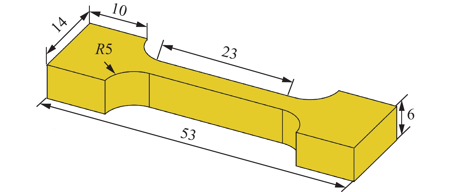
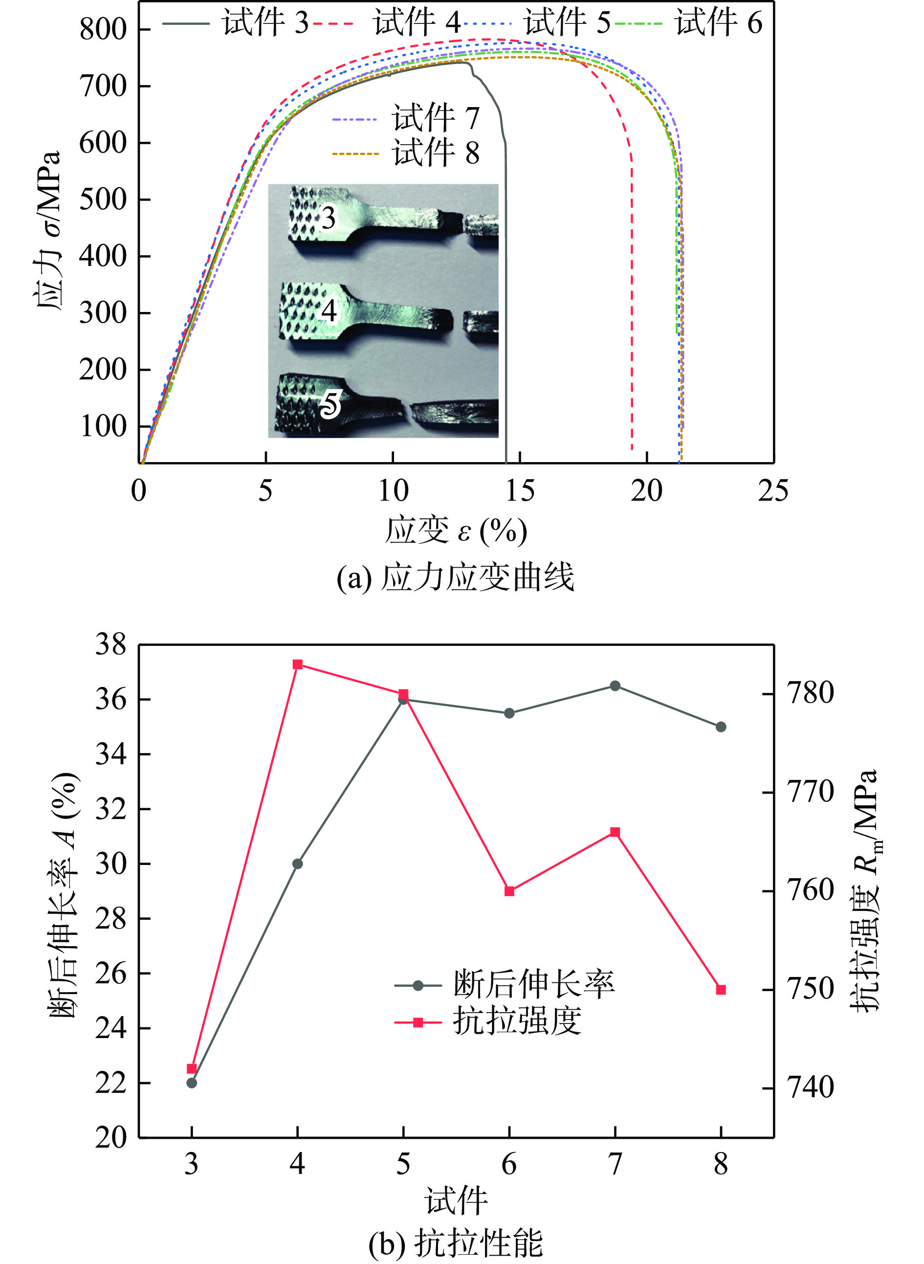
对焊后的焊接接头进行取样加工,按照GB/T 228.1—2010《金属材料拉伸试验 第1部分:室温试验方法》以及GB/T 3075—2008《金属材料 疲劳试验 轴向力控制方法》标准进行室温拉伸和疲劳性能测试. 母材和焊接接头的拉伸试样各4件,焊接接头试样均断在母材区,如图8所示.
对拉伸试样进一步观察可以发现,焊缝及其附近试样宽度大于母材位置,颈缩主要发生在试样上的母材区域. 由于试样上存在两道焊缝,呈现出特有的波浪形态,可知由于焊缝区晶粒尺寸小于母材,发生细晶强化,强度高于母材,滑移主要发生在母材区域.
测试的具体结果见表2,从表2中可以看出,母材的抗拉强度平均值为1153 MPa、断后伸长率为13.3%、断面收缩率为31%,嵌入式线性摩擦焊接头的抗拉强度均基本与母材等强,但是断后伸长率和断面收缩率低于母材. 母材和接头疲劳试样均为15件,得到母材在应力集中系数Kt = 1 (光滑试样),应力比R = −1,循环周次Nf = 1 × 10⁷条件的高周疲劳极限值为521 MPa,接头高周疲劳强度值略高于母材,分析可能是位于圆弧形疲劳试样中心的焊缝区组织细化导致.
表 2 接头性能Table 2. Mechanical properties of joints位置 抗拉强度Rm/MPa 断后伸长率A(%) 断面收缩率Z(%) 高周疲劳强度σD/MPa 母材 1153 13.3 31 521 接头 1188.5 7.8 20.1 543 由此可见,嵌入式线性摩擦焊接头具有较好的拉伸和高周疲劳强度,可以达到与母材等强.
3. 结论
(1)嵌入式线性摩擦焊接头呈V形,由于楔块向顶锻侧试件内部进给的运动形式,焊缝宽度呈现上方窄,下方宽,顶锻侧热力影响区金属变形程度大于振动侧楔块侧. 由于大量飞边金属在接头底部聚集,底部存在一个仅受热影响区域,该区域内组织与传统线性摩擦焊接头中的热力影响区组织有所不同.
(2)采用该接头形式进行焊接,焊缝上部出现了深度在0.5 mm以内的未焊合缺陷,应优化工艺进行重点控制或在零件上该处留有一定加工余量.
(3)采用嵌入式线性摩擦焊的钛合金接头拉伸强度及高周疲劳强度均达到与母材等强,断裂位置都位于母材区域.
-
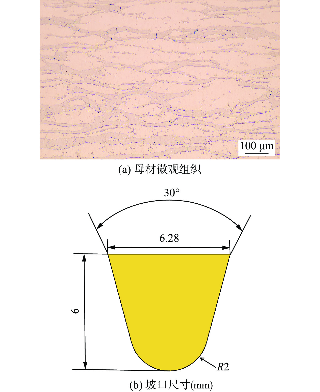
![]()
图 1 母材及U形坡口尺寸
Figure 1. Base material and U-groove size. (a) base material microstructure; (b) groove size (mm)
![]()
图 3 坡口填充焊接示意图
Figure 3. Schematic diagram of groove filler welding. (a) four slices; (b) three slices
![]()
图 6 拉伸试验结果
Figure 6. Tensile test results. (a) stress strain curve;(b) tensile properties
![]()
图 7 拉伸断口形貌
Figure 7. Tensile fracture profile. (a) specimen 3; (b) local enlargement of region A; (c) high magnification enlargement of region A; (d) specimen 4; (e) local enlargement of region B; (f) high magnification enlargement of region B; (g) specimen 5; (h) local enlargement of region C; (i) high magnification enlargement of region C
![]()
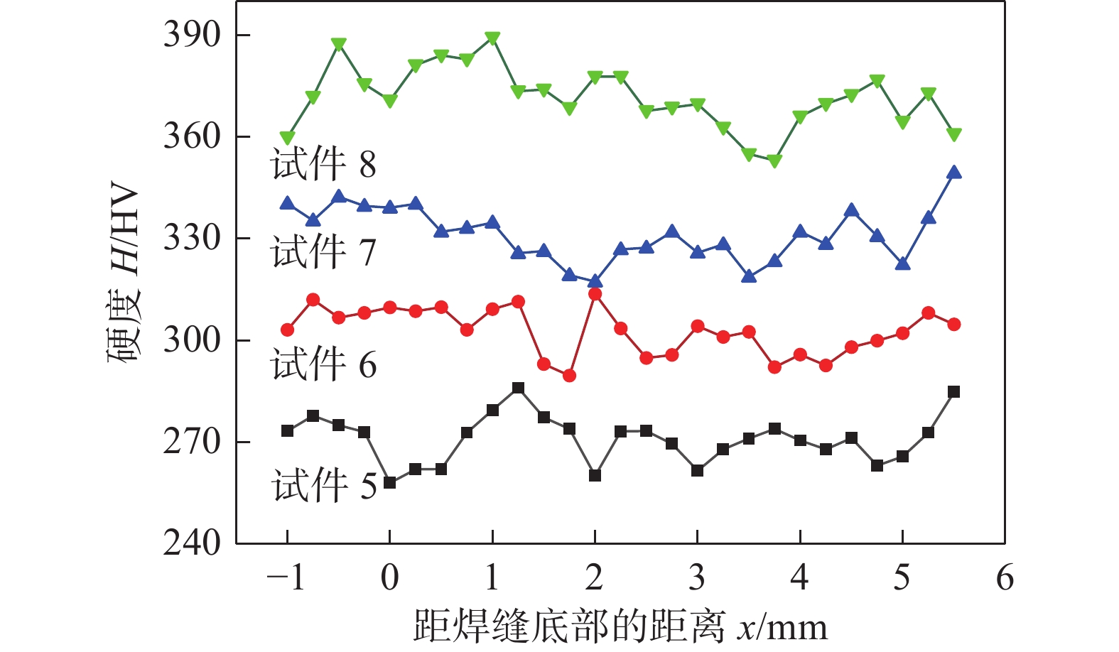
图 8 焊缝底部至顶部的显微硬度分布
Figure 8. Microhardness distribution from the bottom to the top of the weld
![]()
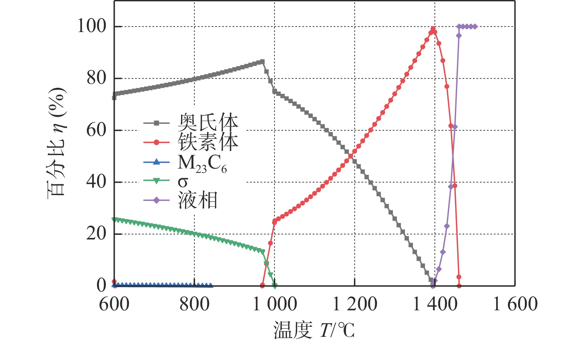
图 9 焊缝组织从
1500 ℃到600 ℃的析出相图Figure 9. Precipitation phase diagram of the weld tissue from
1500 ℃ to 600 ℃![]()
图 10 焊缝微观组织
Figure 10. Microstructure of the weld zone. (a) middle of cap weld; (b) cap weld fusion zone; (c) middle of weld; (d) reheat affected zone; (e) upper weld root region under rapid cooling; (f) lower weld root fusion boundary
表 1 焊丝及母材化学成分(质量分数,%)
Table 1 Welding wire and base material chemical compositions
材料 C Si Mn Cr Mo Ni Cu N Fe S32101 0.023 0.59 4.90 21.50 0.26 1.62 0.24 0.21 余量 ER- 2209 0.022 0.35 1.59 22.56 3.05 7.62 0.06 0.15 余量  下载: 导出CSV
表 2 焊接工艺参数
Table 2 Process parameters of welding
试件 激光功率
P/W送丝速度
vw/(cm·min−1)填充次数
n/次抬升高度
h/mm1 5000 462 3 2.0 2 5300 462 3 2.0 3 5600 462 3 2.0 4 6000 462 3 2.0 5 5000 346 4 1.5 6 5300 346 4 1.5 7 5600 346 4 1.5 8 6000 346 4 1.5
下载: 导出CSV
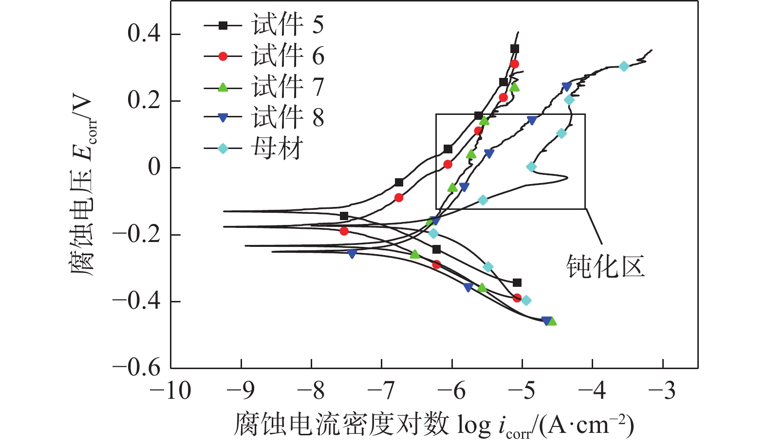
表 3 自腐蚀电位和自腐蚀电流
Table 3 Self-corrosion potential and self-corrosion current
位置 腐蚀电压
Ecorr /V电流密度
icorr /(10−8 A·cm−2)试件5 −0.106 5.08 试件6 −0.170 4.98 试件7 −0.234 28.30 试件8 −0.248 20.40 母材 −0.171 55.00
下载: 导出CSV
表 4 焊缝和母材化学元素含量(质量分数,%)
Table 4 Chemical element contents of the weld and base material
位置 C Si Mn Cr Mo Ni N Fe 试件5 0.015 1.00 2.06 23.67 2.36 6.03 0.24 余量 试件6 0.013 1.08 2.91 23.34 1.90 4.91 0.29 余量 试件7 0.012 1.38 2.30 23.23 2.23 5.71 0.27 余量 试件8 0.016 0.92 2.38 23.65 2.03 5.33 0.28 余量 母材 0.024 1.02 4.71 23.32 0.49 1.30 0.22 余量
下载: 导出CSV
表 5 铬当量和镍当量
Table 5 Chromium equivalent and nickel equivalent
位置 铬当量Creq(%) 镍当量Nieq(%) Creq/Nieq 试件 27.53 15.010 1.83 试件 26.86 15.845 1.69 试件 27.53 15.650 1.75 试件 27.06 15.610 1.73 母材 25.34 10.975 2.30
下载: 导出CSV
-
[1] Afzali N, Jabour G, Stranghoner N, et al. A comparative study into the fracture toughness properties of duplex stainless steels[J]. Journal of Constructional Steel Research, 2024, 212: 108283. doi: 10.1016/j.jcsr.2023.108283
[2] Sakata M, Kadoi K, Inoue H. Age-hardening behaviors of the weld metals of 22% Cr and 25% Cr duplex stainless steels at 400° C[J]. Journal of Nuclear Materials, 2023, 581: 154438. doi: 10.1016/j.jnucmat.2023.154438
[3] Yang Z N, Li Y, Xu Z G, et al. Characterization of σ-phase precipitation and effect on performance in duplex stainless steel S31803[J]. Engineering Failure Analysis, 2024, 157: 107836. doi: 10.1016/j.engfailanal.2023.107836
[4] Pan Y, Sun B Z, Chen H T, et al. Stress corrosion cracking behavior and mechanism of 2205 duplex stainless steel under applied polarization potentials[J]. Corrosion Science, 2024, 231: 111978. doi: 10.1016/j.corsci.2024.111978
[5] Ning J, Jie S Y, Guo C C, et al. Influence of environmental pressure on the energy coupling and droplet transition behavior in laser welding with filler wire[J]. Journal of Manufacturing Processes, 2024, 116: 109 − 119. doi: 10.1016/j.jmapro.2024.02.053
[6] Hu Y, Shi Y H, Wang K, et al. Effect of heat input on the microstructure and mechanical properties of local dry underwater welded duplex stainless steel[J]. Materials, 2023, 16(6): 2289. doi: 10.3390/ma16062289
[7] Ke W C, Liu Y, Biruke F T, et al. Numerical study on multiphase evolution and molten pool dynamics of underwater wet laser welding in shallow water environment[J]. International Journal of Heat and Mass Transfer, 2024, 220: 124976. doi: 10.1016/j.ijheatmasstransfer.2023.124976
[8] Sun G F, Wang Z D, Lu Y, et al. Underwater laser welding/cladding for high-performance repair of marine metal materials: a review[J]. Chinese Journal of Mechanical Engineering, 2022, 35(1): 42 − 60. doi: 10.1186/s10033-022-00722-3
[9] Sun J Q, Yang Y, Wang K, et al. A comparative study on the performance and microstructure of 304NG stainless steel in underwater and air laser welding[J]. Materials, 2024, 17(15): 3854. doi: 10.3390/ma17153854
[10] Liao H P, Wang Z M, Chi P, et al. Double pulsed current adopted in local dry underwater WAAM to simultaneously enhanced strength and ductility of 308 L multi-layer component[J]. Journal of Manufacturing Processes, 2024, 118: 389 − 406. doi: 10.1016/j.jmapro.2024.03.066
[11] Zhu Y H, Zhang Y J, Li C W, et al. Investigation of microstructure, oxides, cracks, and mechanical properties of Ti-4Al-2V joints prepared using underwater wet laser welding[J]. Materials, 2024, 17(8): 1778. doi: 10.3390/ma17081778
[12] Zhu X Y, Yu F, Wu D K, et al. Laser-induced damage of an anti-resonant hollow-core fiber for high-power laser delivery at 1 µm[J]. Optics Letters, 2022, 47(14): 3548 − 3551. doi: 10.1364/OL.457749
[13] Hu J, Guo L. Study of dynamic welding pool for AZ31B magnesium alloy with adjustable ring mode laser welding[J]. The International Journal of Advanced Manufacturing Technology, 2024, 132(7): 3313 − 3332.
[14] Li X, Liu C, Wang X Y, et al. Effect of microstructure on small fatigue crack initiation and early propagation behavior in super austenitic stainless steel 654SMO[J]. International Journal of Fatigue, 2024, 179: 108022. doi: 10.1016/j.ijfatigue.2023.108022
[15] Yang X, Wang S , Pan H P, et al. Microstructure transformation in laser additive manufactured NiTi alloy with quasi-in-situ compression[J]. Micromachines, 2022, 13(10): 1642.
[16] Karimi A, Karimipour A, Akbari M, et al. Investigating the mechanical properties and fusion zone microstructure of dissimilar laser weld joint of duplex 2205 stainless steel and A516 carbon steel[J]. Optics & Laser Technology, 2023, 158: 108875.
[17] Liu X C, Li W T, Zhou Y Q, et al. Multiple effects of forced cooling on joint quality in coolant-assisted friction stir welding[J]. Journal of Materials Research and Technology, 2023, 25: 4264 − 4276. doi: 10.1016/j.jmrt.2023.06.248
[18] Han Y D, Zhang Y K, Jing H Y, et al. Microstructure and corrosion studies on different zones of super duplex stainless steel UNS S32750 weldment[J]. Frontiers in Materials, 2020, 7: 251. doi: 10.3389/fmats.2020.00251
[19] Xie X F, Li J W, Jiang W C, et al. Nonhomogeneous microstructure formation and its role on tensile and fatigue performance of duplex stainless steel 2205 multi-pass weld joints[J]. Materials Science & Engineering A, 2020, 786: 139426.
[20] Shen S K, Hao L Y, Wen K K, et al. Improving mechanical properties of EP823 ferritic/martensitic steel via increasing silicon contents[J]. Journal of Materials Engineering and Performance, 2023: 1 − 15.
[21] Li M M, Zou D N, Li Y N, et al. Effect of cooling rate on pitting corrosion behavior of 904L austenitic stainless steel in a simulated flue gas desulfurization solution[J]. Metals and Materials International, 2023, 29(3): 730 − 747. doi: 10.1007/s12540-022-01255-z
[22] Tembhurkar C, Kataria R, Ambade S, et al. Effect of fillers and autogenous welding on dissimilar welded 316L austenitic and 430 ferritic stainless steels[J]. Journal of Materials Engineering and Performance, 2021, 30: 1444 − 1453. doi: 10.1007/s11665-020-05395-4
[23] Sun J L, Tang H J, Wang C L, et al. Effects of alloying elements and microstructure on stainless steel corrosion: a review[J]. Steel Research International, 2022, 93(5): 2100450. doi: 10.1002/srin.202100450
-
期刊类型引用(3)
1. Tiejun MA,Zhenguo GUO,Xiawei YANG,Junlong JIN,Xi CHEN,Jun TAO,Wenya LI,Achilles VAIRIS,Liukuan YU. Plastic flow and interfacial bonding behaviors of embedded linear friction welding process:Numerical simulation combined with thermophysical experiment. Chinese Journal of Aeronautics. 2025(01): 92-103 .  必应学术
必应学术
2. 李菊,刘川,常川川,季亚娟. TC17钛合金线性摩擦焊接头内部残余应力测试分析. 热加工工艺. 2024(09): 34-38+44 . 百度学术
3. 王浩,胡怡宁,王涛. 不同热处理工艺下增材制造TC17钛合金组织与摩擦学性能研究. 中国激光. 2024(12): 135-146 . 百度学术
其他类型引用(1)


计量
- 文章访问数: 105
- HTML全文浏览量: 14
- PDF下载量: 57
- 被引次数: 4
