
Analysis of dynamic stress-strain characteristics of AH36 steel welded joint
-
摘要:
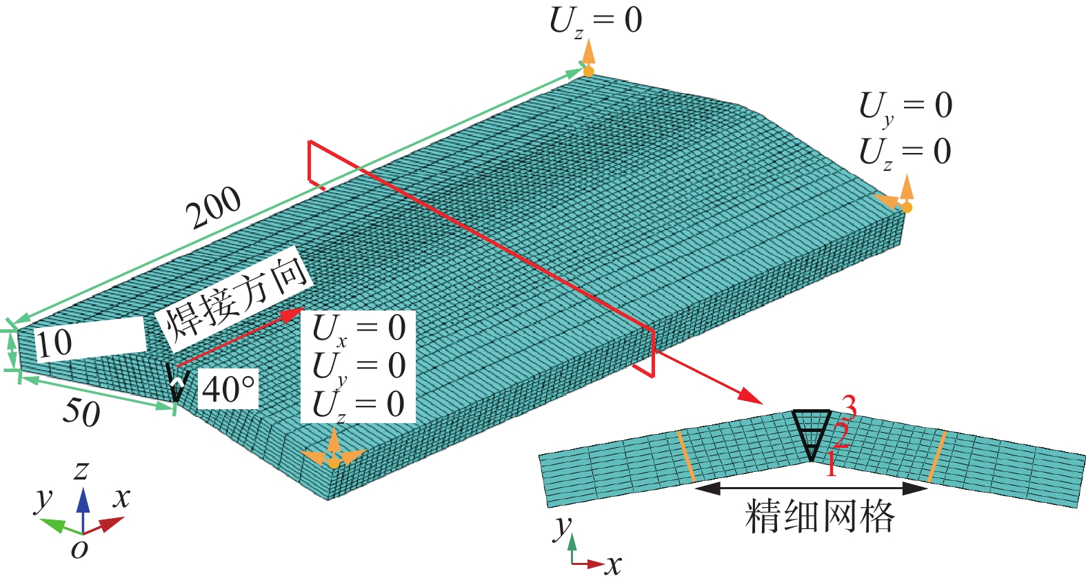
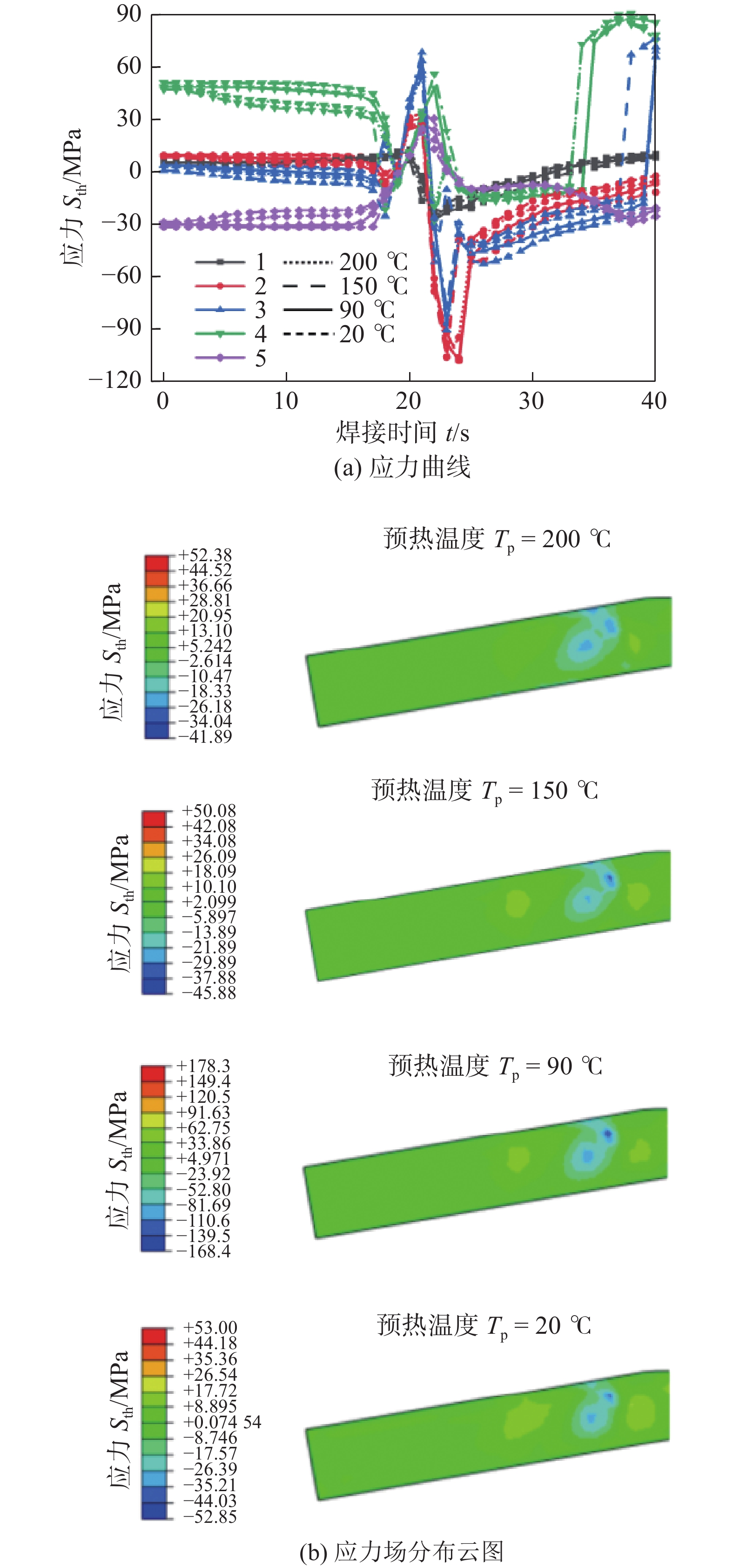
基于热弹塑性法研究了160°对接AH36钢焊接接头动态应力应变过程,同时制作试样,利用三维全场应变测量分析系统记录焊接应变的动态变化,验证了焊接有限元结果的准确性. 分析了预热温度和焊接速度对动态应力应变的影响. 研究结果表明,随着预热温度的增加,焊接变形逐渐减小. 预热温度为200 ℃时的平均焊接变形量比未预热时的平均焊接变形量降低了34.6%,同时改善了焊接应力场的分布情况,增加焊缝及热影响区的压应力分布区域,但应力幅值对预热温度的改变不敏感. 焊接变形随焊接速度增大而增大,当焊接速度大于5 mm/s时,增长趋势逐渐平缓,焊接变形场等势分布面积减小. 随着焊接速度的增加,焊接压应力场分布区域减小,焊接拉应力场分布区域增大,焊接速度的改变还会造成平板厚度方向中间层厚度处的应力出现波动.
Abstract:Based on the thermal elastic-plastic method, the dynamic stress-strain deformation process of AH36 steel welded joint with 160° butt joint was studied. At the same time, the sample was made, and the dynamic change of welding strain was recorded by three-dimensional full-field strain measurement and analysis system, which verified the accuracy of welding finite element results. The effects of preheating temperature and welding velocity on dynamic stress and strain were analyzed. The results show that with the increase of preheating temperature, the welding deformation decreases gradually. When the preheating temperature is 200 ℃, the average welding deformation is reduced by 34.6% compared with the average welding deformation without preheating. At the same time, the distribution of welding stress field is improved, and the compressive stress distribution area of weld and heat affected zone is increased, but the stress amplitude is not sensitive to the change of preheating temperature. The welding deformation increases with the increase of welding velocity. When the welding velocity is greater than 5 mm/s, the growth trend gradually slows down, and the equipotential distribution area of the welding deformation field decreases. With the increase of welding velocity, the distribution area of welding compressive stress field decreases, and the distribution area of welding tensile stress field increases. The change of welding velocity will also cause the stress of middle layer thickness to fluctuate.
-
0. 序言
高能同步辐射光源(high energy photon source, HEPS)是国家重大科技基础设施建设“十三五”规划确定建设的十个重大科技基础设施之一, 是基础科学和工程科学等领域原创性、突破性创新研究的重要支撑平台. 真空系统是高能同步辐射光源的基础工程,束流只有在真空环境中运行,才能保持足够的寿命,并且不断地被积累和加速,达到设计的能量和流强,并提供高亮度的同步辐射光.
HEPS采用316LN为储存环真空盒法兰以及部分真空盒的主要材料,Inconel625作为快校正磁铁内部薄壁真空盒材料,空间紧张区域两种材料合金管需要对焊[1-2]. HEPS正式运行时,储存环真空盒需要维持超高真空,超高真空的获得需要保证真空盒内表面较高的光洁度,同时,真空环境腔体内表面需要避免狭缝的出现,保证真空盒内表面较低的出气率,维持稳定的超高真空. 所以,真空盒管道对焊,要求焊缝区域需要焊透,且焊缝背面无焊渣出现;同时,由于大气压以及重力变形等要求,为保证真空盒的机械强度,316LN与Inconel625材料的焊接性能的研究极为重要.
国内外学者针对不同的工作要求开展了316LN与 Inconel625对焊焊接接头性能研究,对焊接后的焊缝进行了微观组织以及力学性能的研究[3-10],但是针对异种材料超高真空应用焊接的焊接工艺以及不同焊接方式下焊接参数对焊缝性能的影响研究较少[11-18]. 激光焊接作为高能束焊接的一种,束流的功率密度高、焊缝深宽比大、工件产生的变形小,非常适合Inconel625以及316LN这类高熔点金属薄壁管件的焊接.
文中对316LN以及Inconel625材料的合金管进行了激光对焊试验,采用光学显微镜与扫描电子显微镜观察并分析了各组试样的接头形貌、微观组织及化学成分,并对焊件进行力学性能分析,从而为HEPS加速器储存环真空盒异种材质合金管的焊接提供工艺指导以及理论依据.
1. 试验方法
采用的试验材料为外径24 mm、内径22 mm的316LN以及Inconel625圆形薄壁合金管件,其化学成分分别见表1和表2.
表 1 Inconel625化学成分(质量分数,%)Table 1. Chemical compositions of Inconel625C Si Mn Al Ti Ni Cr Fe Co Nb 0.01 0.50 0.50 0.40 0.40 58 ~ 68 20 ~ 30 5.0 1.0 3.1 ~ 4.1 表 2 316LN化学成分(质量分数,%)Table 2. Chemical compositions of 316LNC Si Mn P S Ni Cr Mo N C + N Fe ≤0.03 ≤0.75 ≤2.00 ≤0.03 ≤0.02 10.00 ~ 14.00 16.00 ~ 18.50 0.12 ~ 0.17 0.12 ~ 0.17 ≤0.15 余量 异种材料Inconel625&316LN进行激光管件对接试验前,需要对异种材料管件端口进行处理. 首先采用砂纸将管件焊接面的内壁与外壁打磨去除氧化膜,接着采用丙酮擦拭整个对接口去除油脂. 将准备好的对焊管件316LN管件与Inconel625管件分别装夹到夹具上,装夹时保证对焊管件的同心度. 焊接过程采用20 L/min流量的氩气进行保护以防止焊接过程焊缝高温氧化. 本试验所采用的焊接速度为870 mm/min,夹具转速为300 mm/min,且由于管件壁厚较薄,激光焊接时离焦量为 + 20 mm,激光偏移量为0 mm. 焊接时,首先采用0.4 s的时间和1 200 W的激光功率进行点焊,从而形成两点点固. 然后,分别采用1 000,1 100,1 200,1 300,1 400 W功率对Inconel625&316LN异种材料合金管进行环焊缝焊接.
将焊好的管件切割成尺寸为8 mm × 5 mm的金相试样,随后对镶嵌后的试样采用80 ~ 5 000目砂纸逐级打磨,然后用金刚石抛光剂进行机械抛光. 抛光直至试样成为无划痕、无污染、光滑的镜面后,将试样放置于腐蚀剂(FeCl3(3 g) + HCl(2 mL) + 乙醇(96 mL))中对观察面进行化学浸蚀,腐蚀时间约27 s. 使用光学显微镜观察不同激光功率下试样焊缝的横截面形貌,使用扫描电子显微镜(SEM)对焊缝横截面形貌较好的试样进行焊缝微观形貌观察,并采用X射线衍射仪(XRD)和能谱分析(EDS)进行接头界面物相的鉴定分析. 焊接试样接头的抗拉强度采用力学性能试验机在0.5 mm/min的加载速度下进行测试,并对断裂的试样进行SEM显微分析.
2. 试验结果及分析
2.1 激光对焊表面成形
Inconel625&316LN异种管件对接接头焊缝表面成形如图1所示.图1a ~ 1c为当激光功率为1 000 ~ 1 200 W时,焊缝的正面成形均匀美观,成形较好,背部也有一定的余高,适度熔透,随激光功率增大,可以看出焊缝的背部余高增加. 当激光功率为1 100 W时,正面焊缝成形均匀美观,且无表面飞溅,但是由于激光冲击使部分熔化金属下落,在管道内部形成飞溅残留. 背部的焊缝成形较好,呈现适度熔透状态,只有很小的背部余高. 当激光功率为1 000, 1 100 W时,焊缝背面均存在大量飞溅,而当功率增大至1 200 W时,此时焊缝背部无飞溅痕迹,成形美观,余高均匀. 3道焊缝均存在随焊接过程进行出现焊缝熔宽变化的现象,这主要由于热积累导致. 如图1d和图1e所示,当激光功率进一步增大到1 300, 1 400 W时,焊缝的成形出现了严重的不稳定现象,热积累效应十分明显,且焊穿现象严重,无法实现可靠焊接.
![]() 图 1 Inconel625&316LN异种管件焊缝成形Figure 1. Weld forming of Inconel625&316LN. (a) 1 000 W; (b) 1 100 W; (c) 1 200 W; (d) 1 300 W; (e) 1 400 W
图 1 Inconel625&316LN异种管件焊缝成形Figure 1. Weld forming of Inconel625&316LN. (a) 1 000 W; (b) 1 100 W; (c) 1 200 W; (d) 1 300 W; (e) 1 400 W2.2 激光对焊接头焊缝截面形貌
Inconel625&316LN激光焊接接头横截面形貌如图2所示. 可以看出,随着激光焊接功率的增加,316LN母材的熔化量增加,这使得焊缝中的316LN含量增加. 图2a ~ 2d分别为激光功率1 000,1 100,1 200,1 300 W时的焊缝截面形貌. 当激光功率小于1 300 W时,焊缝成形良好,除出现焊缝表面受熔池内部重力作用出现略微下塌现象外,无熔池内气孔、微裂纹等缺陷产生. 如图2e所示,当激光功率为1 400 W时,大量金属发生熔化,焊缝熔池体积增大,同时此时熔池过热,在全位置焊接过程中受热积累影响,熔池内部发生局部位置开裂现象,焊缝截面成形较差.
![]() 图 2 Inconel625&316LN管件焊缝横截面形貌Figure 2. Weld cross section morphology of Inconel625&316LN. (a) 1 000 W; (b) 1 100 W; (c) 1 200 W; (d) 1 300 W; (e) 1 400 W
图 2 Inconel625&316LN管件焊缝横截面形貌Figure 2. Weld cross section morphology of Inconel625&316LN. (a) 1 000 W; (b) 1 100 W; (c) 1 200 W; (d) 1 300 W; (e) 1 400 W2.3 激光对焊焊缝微观组织分析
对不同焊接参数下焊缝表面成形及截面形貌进行对比分析,1 200 W激光功率下激光焊接接头成形质量最好. 采用光学显微镜观察焊缝显微组织,图3为激光功率1 200 W下Inconel625&316LN薄壁合金管激光焊接接头显微形貌. 从图3可以看出,界面处熔合良好,无气孔、裂纹等缺陷产生,形成明显冶金结合. 熔化的镍与钢互溶形成焊缝,在钢与焊缝的连接界面处出现一层反应层,反应层过渡明显,厚度约30 μm,该区域的元素扩散现象将通过扫描电子显微镜配合EDS元素分析进一步确定. 由于激光对焊缝的热作用,在钢母材靠近焊缝处出现热影响区,如图3a和图3b,该区域晶粒与母材相比粗大,力学性能较差,实际应用中在外界载荷作用下会成为薄弱环节,影响焊接结构件的强度. 如图3c,焊缝中心部分组织主要以固溶体形式存在,具体固溶体中元素含量将采用EDS元素分析进一步确定. 图3d为镍侧靠近焊缝熔合线附近金相显微形貌,焊缝向镍母材过渡均匀,具体固溶体中元素含量将采用EDS元素分析进一步确定.
![]() 图 3 1 200 W激光功率下Inconel625&316LN焊缝微观组织Figure 3. Weld microstructure of Inconel625&316LN at 1 200 W laser power. (a) meld line of 316LN side; (b) metallographic morphology of base metal of 316LN side; (c) weld center; (d) meld line of Inconel625 side
图 3 1 200 W激光功率下Inconel625&316LN焊缝微观组织Figure 3. Weld microstructure of Inconel625&316LN at 1 200 W laser power. (a) meld line of 316LN side; (b) metallographic morphology of base metal of 316LN side; (c) weld center; (d) meld line of Inconel625 side依据光学显微分析发现,焊缝与镍、钢连接处出现一层元素扩散层,为进一步分析焊缝与母材连接界面处的元素分布,采用MERLIN场发射扫描电子显微镜对界面进行高倍形貌分析,并配合EDS元素分析对界面及焊缝内部局部位置进行元素成分鉴定,如图4所示. 焊缝与镍及钢母材连接界面过渡明显,如图4a和图4c所示. 依据EDS元素分布分析结果,Ni, Fe元素由焊缝到316LN母材过渡均匀,如图4b. 而由镍母材到焊缝方向的元素扩散相对均匀,Fe元素出现明显的元素含量升高现象,在焊缝内部Fe, Ni元素原子比接近相同,如图4d,表明在镍/钢管焊接时,镍一侧发生熔化,钢中Fe等元素向其中过渡,生成Ni∶Fe ≈ 1∶1的固溶体,保留在焊缝内.
![]() 图 4 Inconel625&316LN焊缝形貌以及元素分布Figure 4. Weld morphology and element distribution of Inconel625&316LN joint. (a) interface line scanning direction of 316LN side joint weld; (b) line scan analysis results of 316LN side joint weld; (c) interface line scanning direction of Inconel625 side joint weld; (b) line scan analysis results of Inconel625 side joint weld
图 4 Inconel625&316LN焊缝形貌以及元素分布Figure 4. Weld morphology and element distribution of Inconel625&316LN joint. (a) interface line scanning direction of 316LN side joint weld; (b) line scan analysis results of 316LN side joint weld; (c) interface line scanning direction of Inconel625 side joint weld; (b) line scan analysis results of Inconel625 side joint weld根据EDS线扫分析发现,由焊缝向钢、镍侧的元素扩散较为明显,同时在焊缝内部Fe, Ni元素含量接近,依据焊缝内部光学显微分析及Fe, Ni二元合金相图[19]发现,焊缝内部Fe, Ni互溶主要以固溶体形式存在,则采用EDS点扫对不同位置及形貌的固溶体进行元素分析,如图5及表3所示. 结果表明,不同形貌的固溶体内元素分布基本相同,均为Fe含量高,Fe, Ni原子比接近1∶1,这与EDS线扫预测结果相同,说明焊缝内部固溶体种类为原子比相同的Fe/Ni固溶体.
表 3 Inconel625&316LN能谱分析结果(原子分数,%)Table 3. Energy spectrum analysis of Inconel625&316LN分析点 Fe Ni Cr Mo Nb P1 35.29 36.61 22.02 1.82 4.26 P2 40.93 34.75 19.55 1.17 3.60 P3 38.01 32.49 21.00 1.40 7.10 2.4 激光对焊焊缝力学性能
2.4.1 抗拉强度
为探究激光功率对Inconel625&316LN激光焊接接头力学性能的影响,试验采用Instron 5967室温力学测试系统对不同激光功率下的接头进行抗拉强度测试,试验拉伸速度选取为1 mm/min,为保证数据准确性,每组焊接工艺拉伸3个试验样品. 图6为不同激光功率下Inconel625&316LN激光焊接接头抗拉强度,可发现不同激光功率下接头抗拉强度均可达505 MPa以上,与钢母材基体强度基本相同,当激光功率为1 200 W时,焊接接头强度最高为634 MPa,屈服强度366 MPa. 这可能是由于在焊接过程中,镍与钢内Fe, Ni元素互溶形成的固溶体分布较为均匀,使焊缝强度较高,且不低于母材强度,拉伸试验时在拉力作用下不会优先开裂. 随着热输入增加,焊缝内晶体尺寸逐渐增加,焊缝屈服强度逐渐降低.
2.4.2 断裂形式及断口形貌分析
图7为不同激光功率下Inconel625&316LN管激光焊接接头拉伸断裂情况,可以发现,除激光功率为1 300 W的拉伸试样外,断裂位置均为钢基体,而激光功率为1 300 W的焊接构件的拉伸断裂位置为靠近焊缝的钢热影响区位置,主要由于该区域晶粒尺寸在激光焊接过程中受热量作用增长粗大而形成焊接接头的薄弱环节所致. 图8为激光功率为1 300 W的Inconel625&316LN管激光焊接接头拉伸断口的SEM形貌,可发现其断口内存在大量韧性断裂的韧窝形貌.
![]() 图 8 Inconel625&316LN管激光焊接接头拉伸断口形貌Figure 8. SEM morphology of tensile fracture of laser welded Inconel625&316LN joint
图 8 Inconel625&316LN管激光焊接接头拉伸断口形貌Figure 8. SEM morphology of tensile fracture of laser welded Inconel625&316LN joint3. 结论
(1) 采用激光可实现Inconel625&316LN管的全位置焊接,当激光功率过高时会出现焊缝局部受热开裂现象,合适的焊接工艺参数使焊缝成形良好,内部缺陷较少.
(2) Inconel625&316LN焊缝与母材连接界面元素过渡明显,由于Fe, Ni互溶,Fe, Ni在焊缝中均匀分布.
(3) Inconel625&316LN管激光焊接接头抗拉强度较高,由于焊缝内Fe/Ni固溶体分布均匀,焊接试样连接强度较高,断裂形式以母材韧性断裂为主.
-
![]()
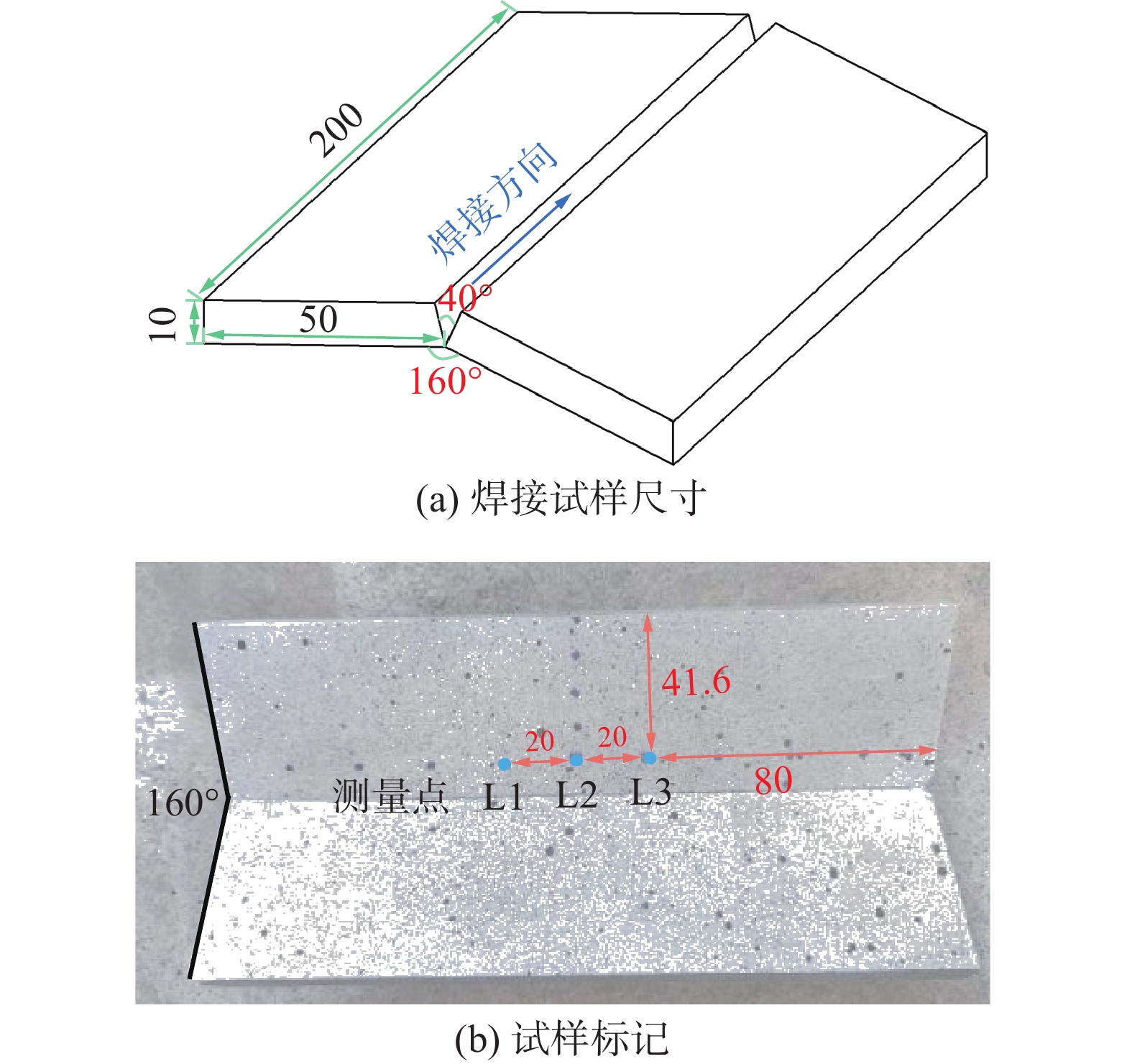
图 1 焊接试样(mm)
Figure 1. Welding specimen. (a) size of welding specimen; (b) specimen marking
![]()
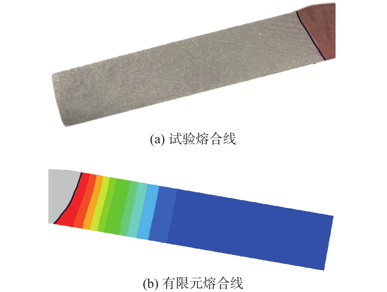
图 5 DIC与有限元结果对比
Figure 5. Comparison of contour of displacement field between DIC and FE
![]()
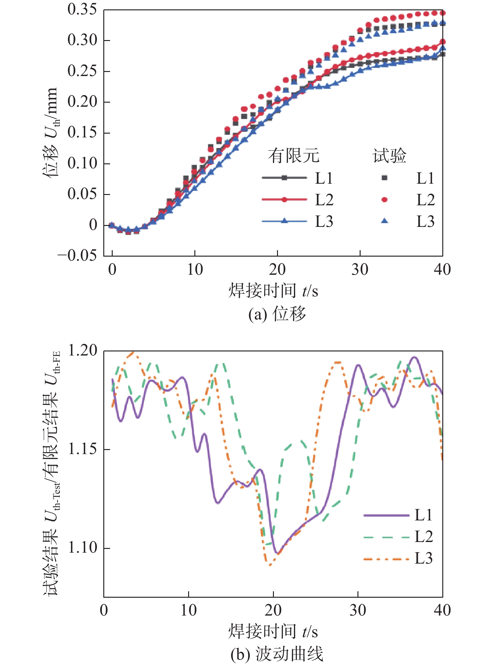
图 6 厚度方向位移曲线
Figure 6. Displacement curves in thickness direction. (a) displacement curves; (b) fluctuation curves
![]()
图 8 不同预热温度下的位移曲线和云图
Figure 8. Displacement curve and contour in different preheat temperatures. (a) Displacement curve; (b) Contour of displacement field
![]()
图 9 不同预热温度下的应力曲线和云图
Figure 9. Stress curve and contour in different preheat temperatures. (a) Stress curve; (b) Contour of stress field distribution
![]()
图 10 不同焊接速度下的位移曲线
Figure 10. Displacement curve in different welding velocities. (a) 2 mm/s; (b) 5 mm/s; (c) 10 mm/s
![]()
图 11 不同焊接速度下的位移场云图
Figure 11. Contour of displacement field distribution in different welding velocities
![]()
图 12 不同焊接速度下的应力曲线
Figure 12. Stress curve in different welding velocities. (a) welding velocity 2 mm/s; (b) welding velocity 5 mm/s; (c) welding velocity 10 mm/s
![]()
图 13 不同焊接速度下的应力场分布云图
Figure 13. Contour of stress field distribution in different welding velocities. (a) welding velocity 2 mm/s; (b) welding velocity 5 mm/s; (c) welding velocity 10 mm/s
![]()
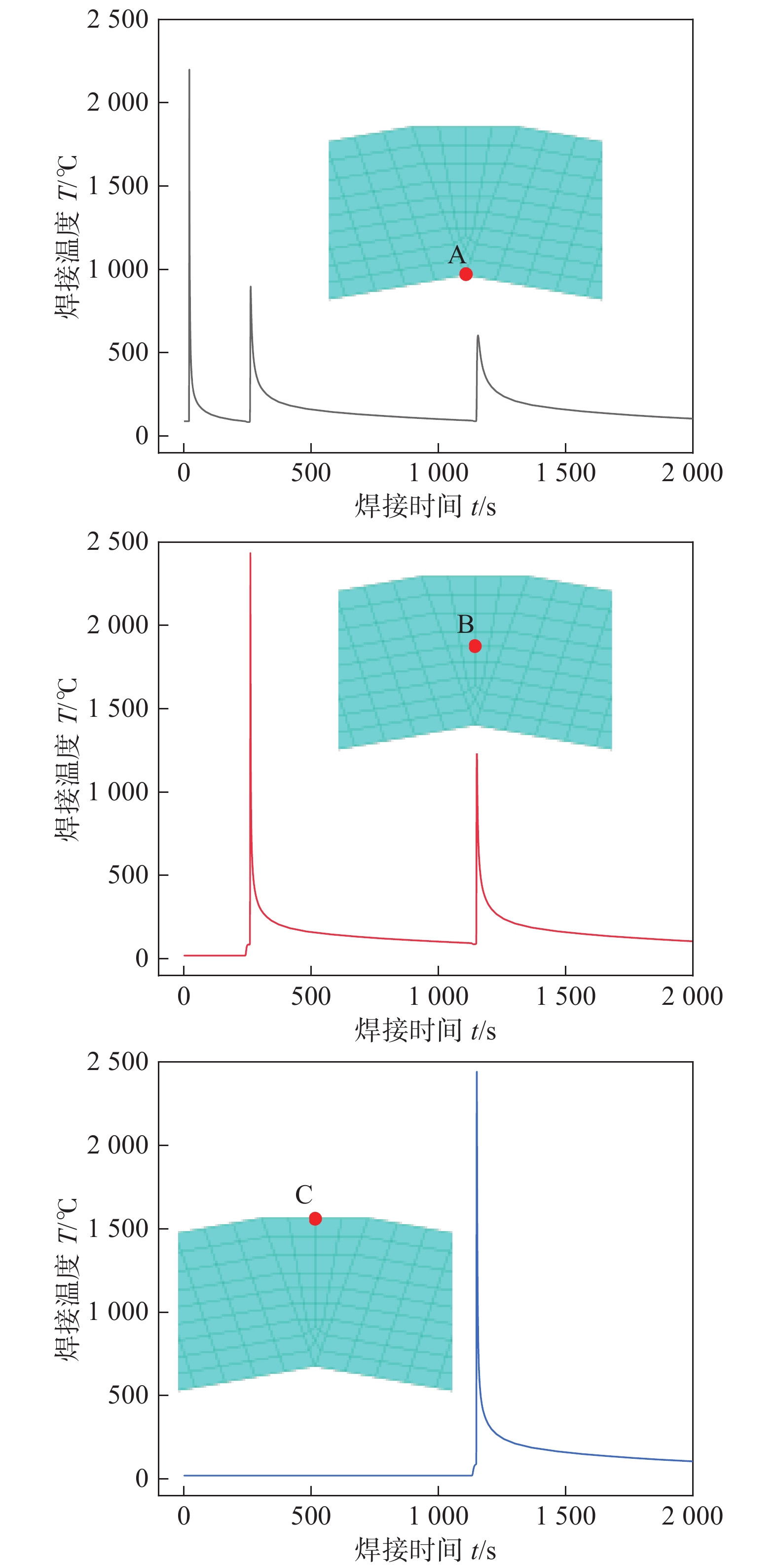
图 14 不同焊接速度下的温度场对比
Figure 14. Comparison of temperature contour in different welding velocities. (a) welding velocity 2 mm/s; (b) welding velocity 5 mm/s; (c) welding velocity 10 mm/s
表 1 焊接参数
Table 1 Welding parameters
焊缝深度
h / mm电压
V / V电流
I / A焊接速度
v / (mm·s−1)热输入
q / (J·mm−1)3 18 80 5 230.4 3 21 110 5 369.6 3.5 23 130 5 478.4  下载: 导出CSV
表 2 AH36钢的高温属性
Table 2 High temperature properties of AH36 steel
温度
T / ℃热膨胀系数
α / (10−5·K−1)屈服强度
ReL / MPa弹性模量
E / GPa泊松比
μ密度
ρ / (g·cm−3)比热
C / (J·kg−1·K−1)导热系数
λ / (W·m−1·K−1)20 1.67 265 200 0.29 7.80 465 15.0 100 1.70 237 190 0.30 7.79 500 15.1 300 1.83 170 168 0.31 7.75 512 18.0 500 1.95 142 157 0.32 7.65 546 20.4 700 2.00 122 151 0.33 7.57 589 22.9 900 2.02 68 120 0.33 7.50 615 25.5 1100 2.03 36 76 0.33 7.47 647 29.5 1300 2.10 17 20 0.34 7.35 697 33.0 1500 2.13 8 10 0.39 7.33 704 32.0
下载: 导出CSV
表 3 不同预热温度下各节点的位移
Table 3 Displacement of points under different preheat temperatures
节点 20 ℃ 90 ℃ 150 ℃ 200 ℃ 位移峰值
Umax / mm最终位移
U / mm位移峰值
Umax / mm最终位移
U / mm位移峰值
Umax / mm最终位移
U / mm位移峰值
Umax / mm最终位移
U / mm1 −0.475 −0.690 −0.438 −0.651 −0.386 −0.600 −0.262 −0.486 2 −0.432 −0.650 −0.391 −0.608 −0.336 −0.554 −0.211 −0.439 3 −0.405 −0.624 −0.361 −0.579 −0.305 −0.524 −0.179 −0.408 4 −0.378 −0.597 −0.332 −0.550 −0.274 −0.493 −0.149 −0.376 5 −0.354 −0.572 −0.305 −0.522 −0.258 −0.464 −0.116 −0.348
下载: 导出CSV
表 4 不同预热温度下各节点的应力
Table 4 Stress of points under different preheat temperatures
节点 20 ℃ 90 ℃ 最大应力
σmax / MPa最终应力
σ / MPa最大应力
σmax / MPa最终应力
σ / MPa1 −24.01 8.01 −27.39 9.11 2 −107.29 −11.93 −108.46 −6.98 3 −77.97 65.77 −87.05 68.99 4 86.66 75.19 87.91 85.44 5 32.89 −20.70 −31.42 −22.27 节点 150 ℃ 200 ℃ 最大应力
σmax / MPa最终应力
σ / MPa最大应力
σmax / MPa最终应力
σ / MPa1 −26.41 9.59 −26.03 10.17 2 −106.42 −6.45 −106.57 −2.44 3 −90.92 71.39 76.84 76.84 4 90.37 85.31 87.43 77.99 5 −27.60 −25.62 −29.57 −25.71
下载: 导出CSV
表 5 不同焊接速度下各节点的位移
Table 5 Displacement of points under different welding velocities
节
点2 mm/s 5 mm/s 10 mm/s 位移峰值
Umax / mm最终位移
U / mm位移峰值
Umax / mm最终位移
U / mm位移峰值
Umax / mm最终位移
U / mm1 0.087 −0.423 −0.438 −0.651 −0.509 −0.643 2 0.177 −0.352 −0.391 −0.608 −0.488 −0.618 3 0.223 −0.317 −0.361 −0.579 −0.473 −0.599 4 0.268 −0.283 −0.332 −0.550 −0.456 −0.579 5 0.314 −0.247 −0.305 −0.522 −0.442 −0.560
下载: 导出CSV
表 6 不同焊接速度下各节点的应力
Table 6 Stress of points under different welding velocities
节
点2 mm/s 5 mm/s 10 mm/s 最大应力
σmax / MPa最终应力
σ / MPa最大应力
σmax / MPa最终应力
σ / MPa最大应力
σmax / MPa最终应力
σ / MPa1 −21.94 1.94 −27.39 9.11 11.77 −9.07 2 70.79 4.78 −108.46 −6.98 38.15 −12.05 3 103.43 7.11 −87.05 68.99 56.86 −9.64 4 63.13 3.71 47.99 85.44 49.68 10.67 5 19.73 −8.42 27.44 −22.27 35.22 −6.84
下载: 导出CSV
-
[1] 段斌, 马德志. 现代焊接工程手册(基础卷)[M]. 北京: 化学工业出版社, 2016. Duan Bin, Ma Dezhi. Modern welding engineering handbook (basic) [M]. Beijing: Chemical Industry Press, 2016.
[2] 陈祝年, 陈茂爱. 焊接工程师手册(第三版)[M]. 北京: 机械工业出版社, 2019. Chen Zhunian, Chen Maoai. Handbook for welding engineer [M]. Beijing: China Machine Press, 2019.
[3] Ghafouri M, Ahola A, Ahn J, et al. Numerical and experimental investigations on the welding residual stresses and distortions of the short fillet welds in high strength steel plates[J]. Engineering Structures, 2022, 260: 114269. doi: 10.1016/j.engstruct.2022.114269
[4] Barsoum Z, Barsoum I. Residual stress effects on fatigue life of welded structures using LEFM[J]. Engineering Failure Analysis, 2009, 16(1): 449 − 467. doi: 10.1016/j.engfailanal.2008.06.017
[5] Cui C, Zhang Q, Bao Y, et al. Fatigue life evaluation of welded joints in steel bridge considering residual stress[J]. Journal of Constructional Steel Research, 2019, 153: 509 − 518. doi: 10.1016/j.jcsr.2018.11.003
[6] Jiang W, Xie X, Wang T, et al. Fatigue life prediction of 316L stainless steel weld joint including the role of residual stress and its evolution: Experimental and modelling[J]. International Journal of Fatigue, 2021, 143: 105997. doi: 10.1016/j.ijfatigue.2020.105997
[7] Shajan N, Kumar R, Manik R, et al. Role of residual stress in the failure of HF-ERW welded tubes[J]. Engineering Failure Analysis, 2024, 161: 108342. doi: 10.1016/j.engfailanal.2024.108342
[8] Ghafouri M, Ahola A, Ahn J, et al. Welding-induced stresses and distortion in high-strength steel T-joints: Numerical and experimental study[J]. Journal of Constructional Steel Research, 2022, 189: 107088. doi: 10.1016/j.jcsr.2021.107088
[9] Keränen L, Pylvänäinen M, Kaijalainen A, et al. Residual stresses of MAG-welded ultrahigh-strength steel rectangular hollow sections[J]. Engineering Structures, 2024, 305: 117719. doi: 10.1016/j.engstruct.2024.117719
[10] 朴东光, 潘乾刚, 储继君. 气焊、焊条电弧焊、气体保护焊和高能束焊的推荐坡口[S]. 北京: 中国质检出版社, 2008. Piao Dongguang, Pan Qiangang, Chu Jijun. Recommended joint preparation for gas welding, manual metal arc welding, gas-shield arc welding and beam welding[s]. Beijing: China Quality Inspection Press, 2008.
[11] Zhu Z K, Han Y, Zhang Z, et al. Numerical simulation of residual stress and deformation for submerged arc welding of Q690D high strength low alloy steel thick plate[J]. China Welding, 2021, 30(3): 49 − 58.
[12] 金希红, 曾燕军, 刘恒, 等. 不同残余应力测试方法与数值模拟对比研究[J]. 焊接技术, 2022, 51(1): 24 − 27,113-114. Jin Xihong, Zeng Yanjun, Liu Heng, et al. Comparative study of different residual stress testing methods and numerical simulation[J]. Welding Technology, 2022, 51(1): 24 − 27,113-114.
[13] 乔瑞林, 龙伟民, 秦建, 等. YG8/GH4169异种材料钎焊接头残余应力的数值模拟[J]. 焊接学报, 2024, 45(3): 68 − 74. Qiao Ruilin, Long Weimin, Qin Jian, et al. Numerical simulation of residual stress in YG8/GH4169 dissimilar material brazed joints[J]. Transaction of the China Welding Institution, 2024, 45(3): 68 − 74.
[14] Pavan A R, Arivazhagan B, Vasudevan M, et al. Numerical simulation and validation of residual stresses and distortion in type 316L(N) stainless steel weld joints fabricated by advanced welding techniques[J]. CIRP Journal of Manufacturing Science and Technology, 2022, 39: 294 − 307. doi: 10.1016/j.cirpj.2022.08.010
[15] Goldak J, Chakravarti A, Bibby M. A new finite element model for welding heat sources[J]. Metallurgical Transactions B, 1984, 15(2): 299 − 305. doi: 10.1007/BF02667333
[16] Wang Y F, Feng G J, Pu X W, et al. Influence of welding sequence on residual stress distribution and deformation in Q345 steel H-section butt-welded joint[J]. Journal of Materials Research and Technology, 2021, 13: 144 − 153. doi: 10.1016/j.jmrt.2021.04.059
[17] 王阳. 大型复杂船体结构焊接变形分析方法的研究及应用[D]. 上海: 上海交通大学, 2015. Wang Yang. Investigation and application on the analysis methods of welding distortion in large-scale and complex marine structures[D]. Shanghai: Shanghai Jiao Tong University, 2015.
[18] Wang B, Zhou L, Du J G, et al. Analysis of residual stresses in electron beam welding with filler wire of Ti62A alloy[J]. Journal of Materials Research and Technology, 2023, 23: 985 − 997. doi: 10.1016/j.jmrt.2023.01.081
[19] Sun J M, Liu X Z, Tong Y G, et al. A comparative study on welding temperature fields, residual stress distributions and deformations induced by laser beam welding and CO2 gas arc welding[J]. Materials & Design, 2014, 63: 519 − 530.
[20] Ahn J, He E, Chen L, et al. Prediction and measurement of residual stresses and distortions in fibre laser welded Ti-6Al-4V considering phase transformation[J]. Materials & Design, 2017, 115: 441 − 457.
-
期刊类型引用(23)
1. 崔健伟,张鹏,王立新,聂新宇,李建国,邹运,董悦雷. 层间温度对GMA电弧增材制造不锈钢显微组织和力学性能的影响. 焊管. 2025(01): 35-40+49 .  百度学术
百度学术
2. 陈大林,宋学平,赵青山,高晓菲. 激光功率对CMT电弧增材制造316L不锈钢组织与性能的影响. 电焊机. 2025(02): 39-45 . 百度学术
3. 王梦真,万占东,林健. 电弧增材制造工艺及数值仿真研究进展. 大型铸锻件. 2024(01): 7-12 . 百度学术
4. 李敬勇,李超然,徐育烺,钱鹏. 层间温度对CMT电弧增材制造2Cr13不锈钢薄壁件成形及组织和性能影响. 焊接. 2024(02): 43-50 . 百度学术
5. 黄佳蕾,陈菊芳,姜宇杰,李小平,雷卫宁. TIG电弧增材制造308L不锈钢的显微组织与力学性能分析. 热加工工艺. 2023(01): 38-42+47 . 百度学术
6. 王德伟,鲍正浩. 激光选区增材制造420不锈钢件的组织及力学性能. 焊接技术. 2023(02): 1-4+113 . 百度学术
7. 吴随松,郭纯,刘武猛,营梦,李云. ER316L不锈钢电弧增材制造的组织与性能分析. 新余学院学报. 2023(02): 10-18 . 百度学术
8. 赵阳,范若兰,刘玉锋,王震. 丝材电弧增材制造技术制备316L不锈钢的力学性能. 建筑结构学报. 2023(08): 207-216 . 百度学术
9. 樊世冲,殷凤仕,任智强,韩国峰,付华,刘亚凡,王鸿琪,鲁克锋,孙金钊,王文宇. 基于电弧的多能场复合增材制造技术研究现状. 表面技术. 2023(08): 49-70 . 百度学术
10. 王强,王磊磊,高转妮,杨兴运,占小红. 快速电弧模式增材制造316L不锈钢组织与性能. 焊接学报. 2023(10): 86-93+137-138 . 本站查看
11. 李学军,朱平,尚建路,王龙,陈亮. 电弧增材制造的核级316L不锈钢组织及腐蚀性能研究. 热加工工艺. 2023(19): 24-27 . 百度学术
12. 齐善根,谭振,李建一,王及匀,王立伟,BALAJI Narayanaswamy. Al-Mg-Si合金电弧增材制造工艺参数与性能研究. 金属加工(热加工). 2023(12): 25-31 . 百度学术
13. 李宁,刘少龙,丁雪松,徐雨红,范文磊,苏焕朝,王博玉. 不同工艺参数下0Cr18Ni9钢薄壁管脉冲钨极氩弧焊接头的组织与拉伸性能. 机械工程材料. 2022(02): 58-62 . 百度学术
14. 何鹏,柏兴旺,周祥曼,张海鸥. MIG电弧增材制造6061铝合金的组织和性能. 焊接学报. 2022(02): 50-54+60+116-117 . 本站查看
15. 徐海涛,燕春光,张舒展,史显波,严伟,姜海昌. 奥氏体不锈钢中液析碳化物在高温均匀化过程中的演化. 压力容器. 2022(04): 9-16 . 百度学术
16. 陈晔,姚屏,郑振兴,宾坤,陈美沂. 双脉冲MIG焊工艺参数对316L不锈钢焊缝成形及性能影响研究. 自动化与信息工程. 2022(03): 1-6+14 . 百度学术
17. 赵东升,龙代发,牛堂仁,胡鑫,刘玉君. 316L不锈钢电弧增材制造的微观组织和力学性能. 船舶工程. 2022(09): 14-17+88 . 百度学术
18. 王卫军,郭紫威,代孝红,王鑫. 汽车液压油缸316L不锈钢复合增材工艺及性能研究. 应用激光. 2022(12): 59-65 . 百度学术
19. 李宗玉,张兆栋,贺雅净,王旭,原思宇,刘黎明. 316不锈钢低功率脉冲激光诱导TIG电弧增材制造组织研究. 焊接技术. 2021(05): 8-12 . 百度学术
20. 张兆栋,何胜斌,王奇鹏,靳佩昕,刘黎明. 电弧增材制造工艺方法、增材焊料及后处理的研究现状. 电焊机. 2021(08): 1-10+176 . 百度学术
21. 杨义成,陈健,黄瑞生,徐锴,孙谦,杜兵. 空心钨极焊接关键技术问题及发展现状. 焊接. 2021(05): 1-8+63 . 百度学术
22. 张心保,王志斌,纪平,赵振铎,范光伟. 奥氏体不锈钢中微量元素致焊接缺陷实例分析. 焊接. 2021(05): 47-51+66 . 百度学术
23. 刘黎明,贺雅净,李宗玉,张兆栋. 不同路径下316不锈钢电弧增材组织和性能. 焊接学报. 2020(12): 13-19+97-98 . 本站查看
其他类型引用(17)


计量
- 文章访问数: 93
- HTML全文浏览量: 14
- PDF下载量: 21
- 被引次数: 40
