
Influence of welding process parameters on the microstructure and shear strength of TA15/304SS vacuum diffusion welded joints
-
摘要:
针对TA15钛合金与304不锈钢的异种金属连接及其接头进行了研究. 结果表明,在850 ~ 950 ℃的焊接温度下,接头扩散区(β-Ti区)和(α + β)-Ti双相区的宽度随温度的升高而增加,元素扩散更充分,接头孔洞逐渐减少,观察到逐渐增加的分层产物. 分层产物主要为金属间化合物组成的界面层,即σ-Fe(第1层),FeTi + Fe2Ti(第2层),FeTi + β-Ti(第3层)和β-Ti(第4层). 当焊接温度为900 ℃时,焊接接头达到最大抗剪强度为108 MPa,随着焊接时间的提升,焊接接头的微观形貌,元素成分和物相组织与焊接温度参数接头类似,但焊接时间对接头的抗剪强度影响较小,当焊接时间为80 min时,抗剪强度达到最大,断口出现以韧性为主的脆-韧性混合断裂特征.
Abstract:A study was conducted on the dissimilar metal connection and joint between TA15 titanium alloy and 304 stainless steel. The experimental results show that at welding temperatures of 850-950 ℃, the diffusion zone of the joint (β-Ti) District and (α + β) Ti biphasic region increases with the increase of temperature, element diffusion is more complete, joint pores gradually decrease, and an increasing number of layered products are observed. The layered products are mainly interface layers composed of intermetallic compounds, namely σ-Fe (1st layer), FeTi + Fe2Ti (2nd layer), FeTi + β-Ti (3rd layer) and β-Ti (4th layer). When the welding temperature is 900 ℃, the welded joint reaches its maximum shear strength of 108MPa. As the welding time increases, the microstructure and composition of the welded joint are similar to those of the welding temperature parameter joint, but the influence of welding time on the shear strength of the joint is relatively small. When the welding time is 80 minutes, the shear strength reaches its maximum value, and the fracture surface exhibits a brittle ductile mixed fracture feature dominated by toughness.
-
0. 序言
α-钛合金具有优异的蠕变抗性、抗氧化性及焊接性,而(a + β)-钛合金具有良好的塑性及耐腐蚀性能,近α-钛合金是一种以α相固溶体为基体,稳定状态下含2% ~ 8%的β相,β区急冷后含8% ~ 15%β相的钛合金. 该合金兼具了α-钛合金优良的高温强度、焊接性能和(a + β)-钛合金优良的高温塑性、耐腐蚀性[1]. TA15作为典型的近α-钛合金在高温环境下具有良好服役性能,在飞机发动机零部件、焊接承重部件和形状复杂的大型集成部件中有优异表现.304不锈钢(304 stainless steel,304SS)作为一种应用广泛的铬-镍不锈钢,由于内部氧化铬区和外部氢氧化铬区一起形成了钝化膜区[2],因而具有较高的耐腐蚀性,同时拥有相对较低的成本和良好的耐热性及加工性能,被广泛用作工程结合材料[3]. 解决TA15/304SS连接问题,可以将TA15的轻质、优良的焊接性能、高温强度及塑性与304SS的耐腐蚀性和优良的成形性相结合,是该类钛合金在飞行器发动机叶片、石油钻机配件、化工管道及生物医学等领域应用的基础,具有非常重要经济和工程意义[4].
电弧焊[5]、激光焊[6]等传统的熔焊技术目前已被尝试应用于钛/钢异种金属的焊接,然而异种金属之间的导热系数及膨胀系数存在显著差异[7],使得其接头存在残余应力和不均匀微观结构,焊接上的困难限制了其连接件的生产应用[8]. 真空扩散焊是一种可用于异种材料连接的固相焊方法,能有效避免大气成分对接头的不利影响. Ghosh等人[9]研究了不同温度下TC4/304LSS真空扩散焊,发现Fe,Cr,Ni主要向Ti合金扩散,温度升高会导致接头加速变形和扩散,有助力学性能的提升,但随着焊接温度进一步增加,结合强度逐步降低;Velmurugan等人[10]在650 ℃ ~ 800 ℃的较低温度下对TC4和双相不锈钢进行了30 min的扩散连接,在界面处形成了α-Fe + λ(Fe2Ti + Cr2Ti的固溶体)、λ + FeTi和β-Ti,在较高温度下,结合区宽度也逐渐增加. 在早期研究中,周荣林等人[11]在探索钛合金/钢扩散焊最佳焊接工艺时,在焊接温度880 ℃,保温时间30 min,焊接压力10 MPa下得到的最佳抗剪强度仅为74 MPa;He等人[12]在研究TC4/18Cr-10Ni不锈钢时发现在焊接温度850 ℃时,接头抗剪强度最大仅仅达到72 MPa;Vigraman等人[13]在研究TC4和S304时,将焊接温度作为变量,发现焊接温度的变化对接头力学性能的影响显著,在较低温度875 ℃时,由于界面元素扩散反应及冶金程度较低导致接头拉伸强度仅为98 MPa;高旺旺[14]在研究TA2/S316扩散焊时,保温时间80 min,焊接压力5 MPa不变的情况下,焊接温度从910 ℃升至970 ℃时,接头抗剪强度先升高后降低,在940 ℃时达到最大110.47 MPa,通过前者研究,发现焊接工艺的改变对接头的力学性能产生了显著影响. 目前国内外的钛/钢扩散焊研究大多选择TC4等双相Ti合金,系统地研究了焊接温度对接头的元素扩散、组织形貌及力学性能的影响,然而对于TA15等近α-Ti合金焊接研究则多集中在传统熔焊,对于TA15/304SS的真空扩散焊更是处于探索阶段.文中利用真空扩散焊,探究焊接温度及焊接时间对接头显微组织及力学性能的影响,从而为后续的研究及工程应用提供参考.
1. 试验方法
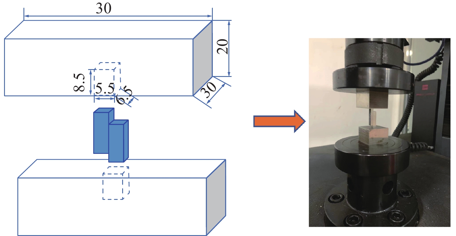
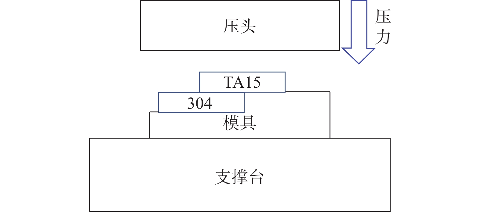
文中所用材料为TA15钛合金以及304SS,两种材料统一加工为正方形板件,其板件为30 mm × 30 mm × 5 mm,化学成分见表1和表2. 对边长为30 mm的TA15和304SS进行焊前磨抛和酒精清洗直至出现无尘镜面,设置焊接温度为850 ~ 950 ℃,温度间隔为50 ℃,保温时间为80 min,压力为10 MPa,设置焊接保温时间为50 ~ 110 min,时间间隔为30 min,焊接温度为900 ℃,压力为10 MPa. 在真空环境下,用CVI超高温真空扩散焊接炉对TA15/304SS板件进行焊接,试样组装如图1所示,焊接完成后,用线切割截取30 mm × 5 mm金相试样,进行粗磨、细磨、抛光然后腐蚀,其中,TA15选用HF∶HNO3∶H2O = 1∶2∶10配比的腐蚀溶液进行腐蚀,采用ZEISS公司Ario Imager.M2m型金相显微镜观察不同参数接头试样显微组织,采用FEI公司QUANTA 250型扫描电子显微镜(scanning electron microscope,SEM)及THERMOFISH公司Noran System 7能谱仪(energy dispersive spectrometer,EDS),对不同参数试样的微观形貌及相关元素扩散情况进行观察与分析,采用MTS SYSTEMS公司CMT5105型电子万能力学试验机对不同参数试样进行室温压缩剪切试验,压缩速率为1.11 mm/min,相同参数下的试样测3次取平均值,并采用FEI公司QUANTA 250型扫描电子显微镜,Noran System 7能谱仪及Bruker公司D8 ADVANCE型X射线衍射仪(X-ray diffractometer,XRD)对不同参数试样剪切断口形貌进行观察与分析,压缩剪切装配图如图2所示.
表 1 TA15化学成分(质量分数,%)Table 1. Chemical compositions of TA15Al V Zr Mo Si 杂质 Ti 7.06 1.40 2.06 1.36 0.026 ≤0.3 余量 表 2 304SS化学成分(质量分数,%)Table 2. Chemical compositions of 304SSC Mn P S Cr Si Ni Fe ≤0.08 ≤2.0 ≤0.045 ≤0.03 18.0 ~ 20 ≤0.8 8.0 ~ 11.0 余量 ![]() 图 1 TA15/304SS真空扩散焊接装配示意图Figure 1. Schematic diagram of TA15/304SS vacuum diffusion welding assembly
图 1 TA15/304SS真空扩散焊接装配示意图Figure 1. Schematic diagram of TA15/304SS vacuum diffusion welding assembly![]() 图 2 TA15/304SS真空扩散焊接试样压缩剪切示意图(mm)Figure 2. Schematic diagram of compression and shear of TA15/304SS vacuum diffusion welding specimens
图 2 TA15/304SS真空扩散焊接试样压缩剪切示意图(mm)Figure 2. Schematic diagram of compression and shear of TA15/304SS vacuum diffusion welding specimens2. 试验结果与讨论
2.1 焊接温度及焊接时间对接头微观形貌与组织的影响
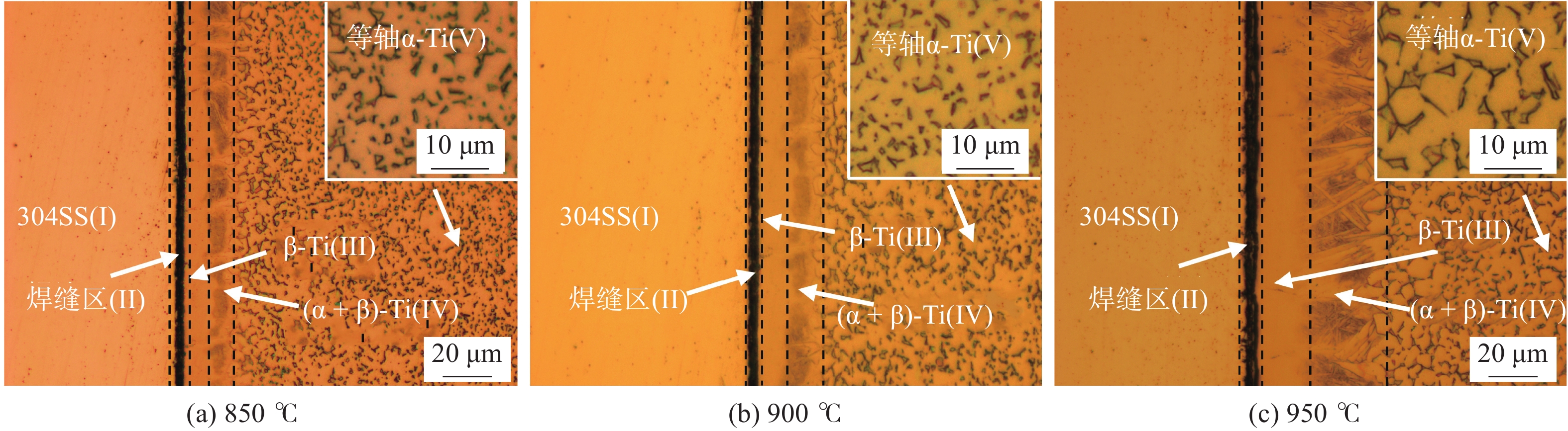
图3和图4为不同焊接温度及焊接时间下的接头金相,所有接头从左至右可依次分为Ⅰ、Ⅱ、Ⅲ、Ⅳ、Ⅴ 5个部分. Ⅰ区为304SS基材;Ⅱ区为一条细长的黑色腐蚀带及部分未焊合孔洞,是腐蚀后的TA15/304SS接头焊缝区域;Ⅲ区在靠近焊缝处,出现了一层光滑平整的β-Ti稳定区域,在逐渐远离焊缝区则出现了针状α-Ti和β-Ti双相共存的区域Ⅳ区;Ⅴ区为TA15的初始等轴α-Ti相. 李明兵等人[15]研究发现在高温环境下,随着温度持续升高,TA15的α相尺寸将增大且沉淀强化作用将明显减弱,这会显著降低位错运动的阻力使钛合金强度大幅度下降. 图3中当焊接温度持续升高时,可以观察到TA15母材侧的等轴α-Ti晶粒尺寸明显增大,说明焊接温度过高会对母材性能产生一定的不利影响,而图4随着焊接时间的增长,TA15母材侧的等轴α-Ti晶粒尺寸没有发生明显增大,因此焊接时间的增长可能对母材的性能影响较小.
![]() 图 3 80 min和10 MPa在不同焊接温度的接头金相形貌Figure 3. Metallographic of joints with different welding temperature at 80 min and 10 MPa. (a) 850 ℃; (b) 900 ℃; (c) 950 ℃
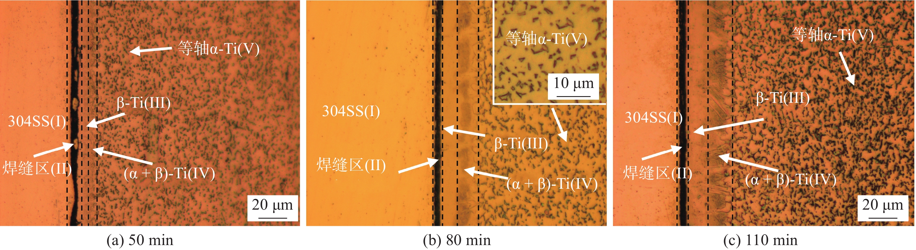
图 3 80 min和10 MPa在不同焊接温度的接头金相形貌Figure 3. Metallographic of joints with different welding temperature at 80 min and 10 MPa. (a) 850 ℃; (b) 900 ℃; (c) 950 ℃![]() 图 4 900 ℃和10 MPa在不同焊接时间的接头金相形貌Figure 4. Metallographic of joints with different welding times at 900 ℃ and 10 MPa. (a) 50 min; (b) 80 min; (c) 110 min
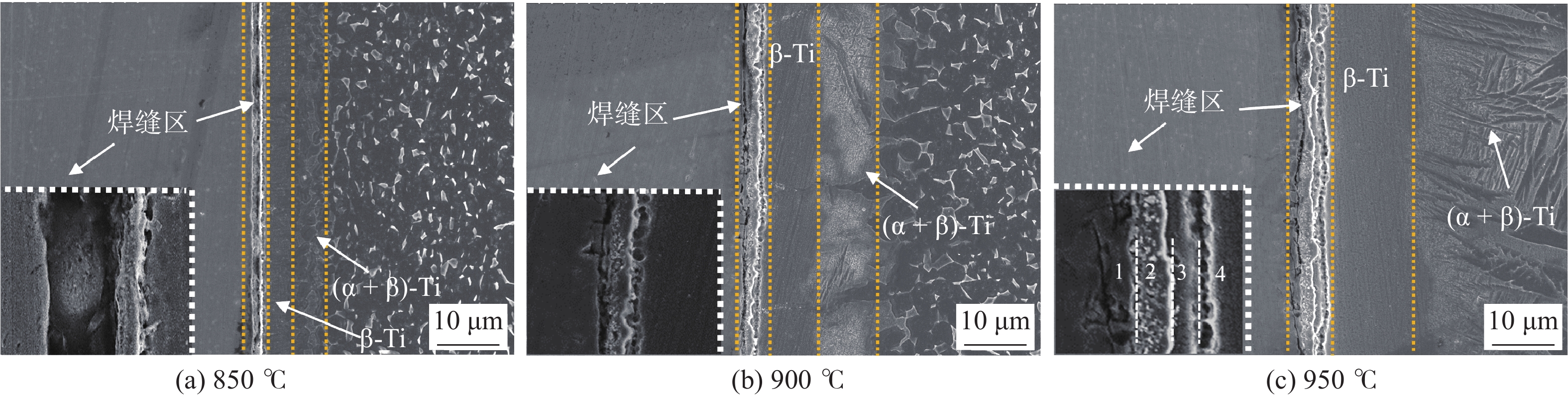
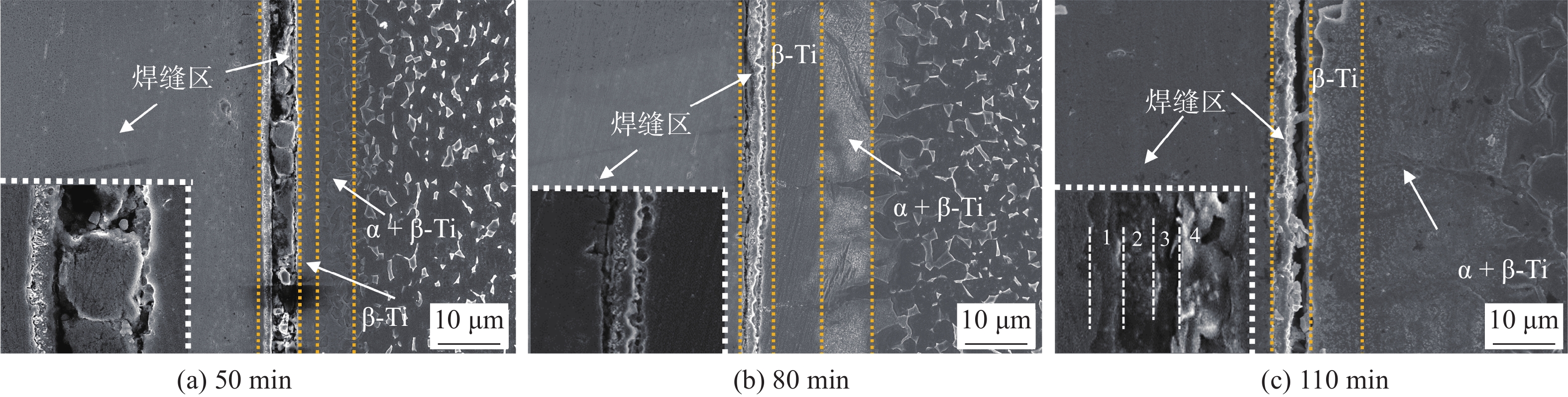
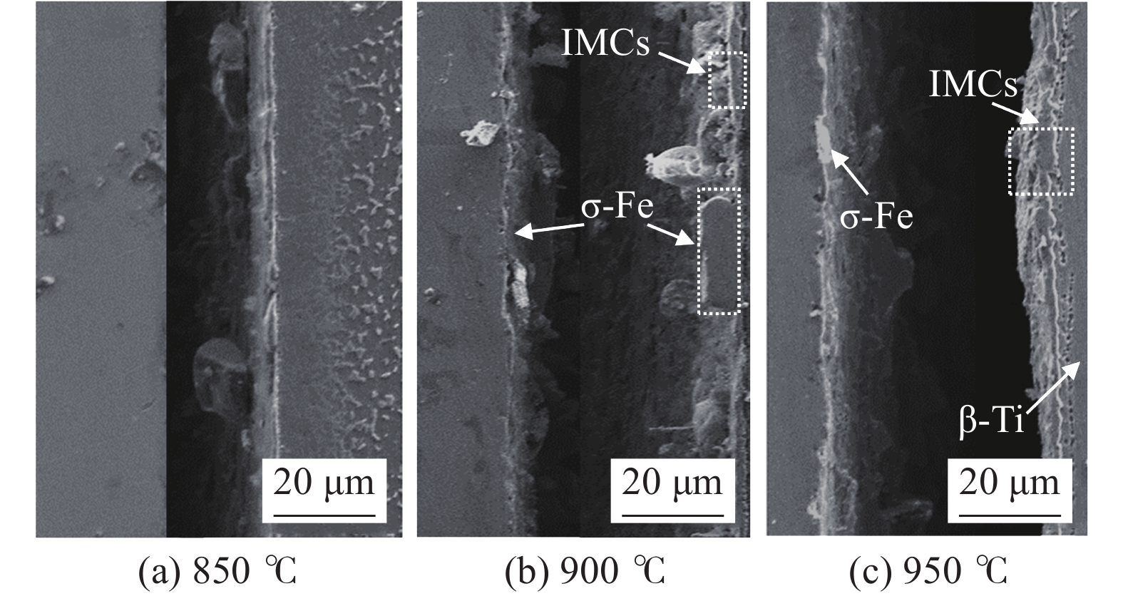
图 4 900 ℃和10 MPa在不同焊接时间的接头金相形貌Figure 4. Metallographic of joints with different welding times at 900 ℃ and 10 MPa. (a) 50 min; (b) 80 min; (c) 110 min图5和图6为不同焊接温度及焊接时间下形成的接头SEM形貌,随着焊接温度及焊接时间的增长,接头元素扩散区域(β-Ti区)逐渐增大,当焊接温度从850 ℃升高至900 ℃时,扩散区宽度增加了60%;从900 ℃升高至950 ℃宽度增加43%,当保温时间从50 min升高至80 min时,扩散区宽度增加了85%;当时间从80 min升高至110 min时宽度仅增加了7%. 根据Nakajima等人[16]研究可知,Fe,Cr,Ni在单晶α-Ti的扩散率比Ti的扩散率高约3 ~ 5个数量级,当温度和时间升高到一定程度时,扩散程度会有不同程度减缓,结合扩散距离,焊接温度更能促进元素的扩散.
![]() 图 5 80 min和10 MPa在不同焊接温度的接头SEM形貌Figure 5. SEM of joints with different welding temperatures at 80 min and 10 MPa treatment. (a) 850 ℃; (b) 900 ℃; (c) 950 ℃
图 5 80 min和10 MPa在不同焊接温度的接头SEM形貌Figure 5. SEM of joints with different welding temperatures at 80 min and 10 MPa treatment. (a) 850 ℃; (b) 900 ℃; (c) 950 ℃![]() 图 6 900 ℃和10 MPa在不同焊接时间的接头SEM形貌Figure 6. SEM of joints with different welding times at 900 ℃ and 10 MPa. (a) 50 min; (b) 80 min; (c) 110 min
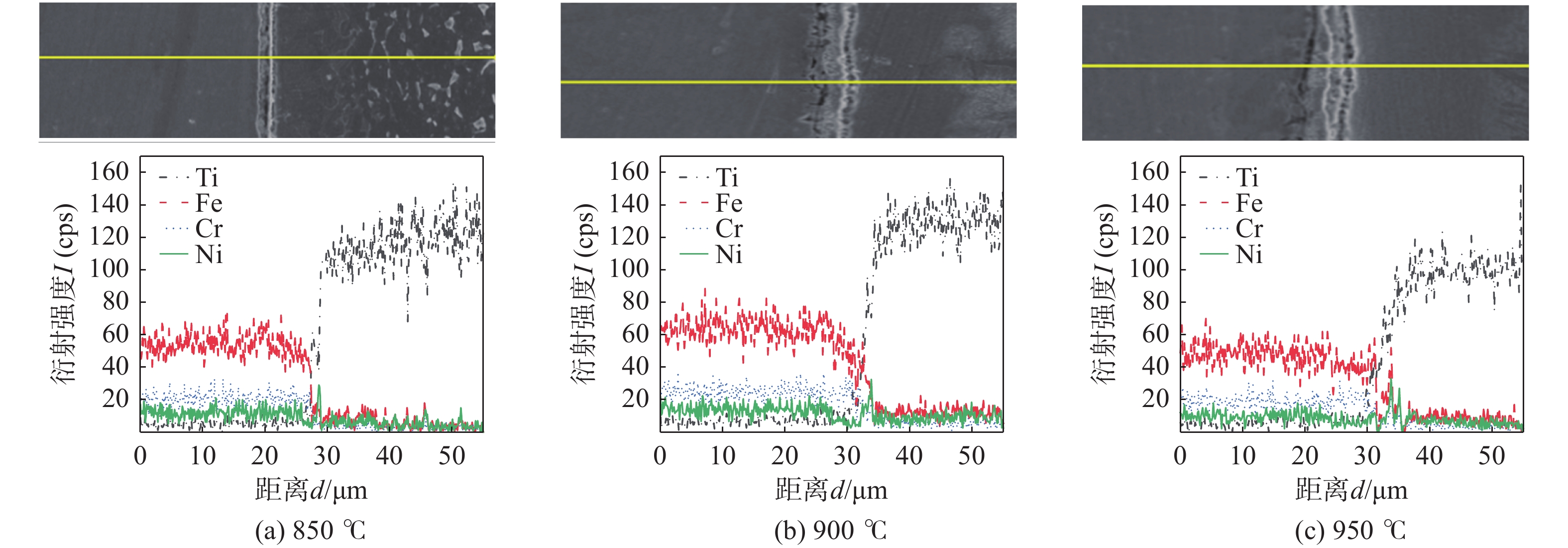
图 6 900 ℃和10 MPa在不同焊接时间的接头SEM形貌Figure 6. SEM of joints with different welding times at 900 ℃ and 10 MPa. (a) 50 min; (b) 80 min; (c) 110 min由图5(a)和图6(a)中的焊缝区观察发现,焊接温度或焊接时间较低时,元素扩散有限,接头产生较大不连续孔洞,随着温度及时间的逐渐增长,如图5(c)和图6(c)在焊缝界面观察到逐渐增加的反应物层. 图7为不同焊接温度下接头元素扩散图,当温度在850 ℃时,界面扩散梯度较小,反应物层较浅,随着温度升高时,界面元素Fe,Ti,Cr浓度梯度变化增大,这表明反应物层的增多,在反应物层中可能产生了不同类型的金属间化合物(intermetallic compounds,IMCs). 选取焊缝区反应物层明显的950 ℃接头进行分析,将焊缝区域根据形象差异具体分为1,2,3,4四层区域,其各层典型形貌及成分EDS如图5(c)及表3所示,分析发现第1层浅色阴影区元素原子含量为69.17%Fe,1.32%Ti,9.85%Ni,19.48%Cr,0.11%Al,0.07%V,该区域为304SS与TA15初始接触区域,结合线扫描元素分布及成分含量可证明在这个焊合界面处存在Cr的富集,Cr的富集是由于上坡扩散特性即Cr的扩散是通过活性扩散而不是浓度梯度扩散[17],结合Fe-Cr-Ni相图所知,Fe,Ni,Ti的存在及Cr的富集可以使试样冷却后保证高温铁素体(σ-Fe)相的稳定,故判断该浅色阴影区域可能存在σ-Fe[18];第2层元素的原子含量为40.61%Fe,42.22%Ti,13.39%N,2.63%Cr,0.55%Al,0.60%V,结合元素形貌及成分分析该区域可能存在Fe2Ti,FeTi化合物;第3层元素的原子含量为13.72%Fe,73.32%Ti,3.53%Ni,2.39%Cr,4.96%Al,2.08%V,结合形貌分析该区域可能存在Ti基体固溶体和FeTi化合物;第4层元素的原子含量为10.86%Fe,75.71%Ti,4.58%Ni,1.57%Cr,5.35%Al,1.93%V. 由Fe-Ti,Ni-Ti和Cr-Ti的二元相图可知,Fe,Ni和Cr在近α-Ti中的溶解度分别为0.047%、0.3%和0.2%,而在β-Ti中的溶解度分别为24.7%、12%和100%. 这些强β-Ti稳定元素在Ti合金晶格中的迁移可以降低α-Ti到β-Ti的转变温度,从而增强Ti的共析转变,使试样冷却过程中形成β-Ti[19],结合形貌分析判断该区域可能存在β-Ti相及部分FeTi化合物.
![]() 图 7 80 min和10 MPa在不同焊接温度下处理下的接头元素线扫描Figure 7. Line scan of joint elements at different welding temperatures of 80 min and 10 MPa. (a) 850 ℃; (b) 900 ℃; (c) 950 ℃表 3 图5(c)接头焊缝区元素含量(质量分数,%)Table 3. Joint weld area element content in Fig 5(c)
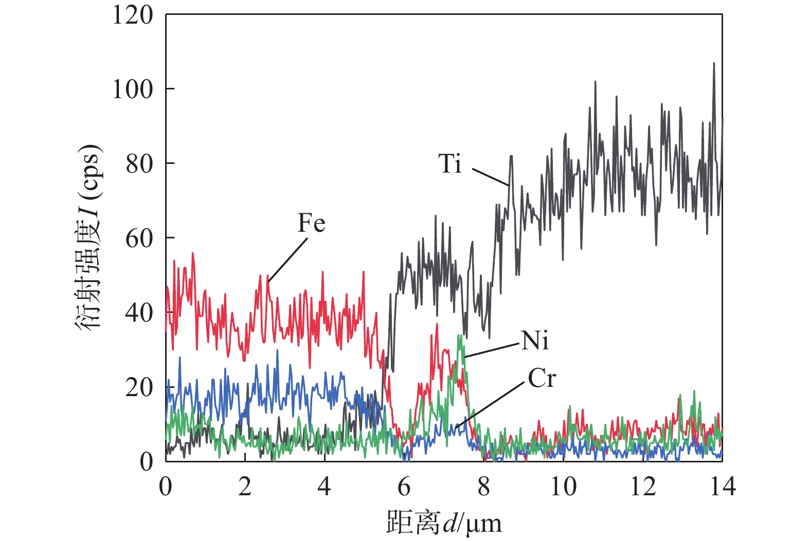
图 7 80 min和10 MPa在不同焊接温度下处理下的接头元素线扫描Figure 7. Line scan of joint elements at different welding temperatures of 80 min and 10 MPa. (a) 850 ℃; (b) 900 ℃; (c) 950 ℃表 3 图5(c)接头焊缝区元素含量(质量分数,%)Table 3. Joint weld area element content in Fig 5(c)层数 Fe Ti Ni Cr Al V 1 69.17 1.32 9.85 19.48 0.11 0.07 2 40.61 42.22 13.39 2.63 0.55 0.60 3 13.72 73.32 3.53 2.39 4.96 2.08 4 10.86 75.71 4.58 1.57 5.35 1.93 在不同焊接时间中,选取焊缝区较宽的110 min参数接头进行分析,为进一步观察焊缝区元素扩散现象,图8为900 ℃,110 min,10 MPa接头焊缝区的元素扩散,发现Fe,Cr,Ni元素在扩散到TA15过程中,未呈现连续变化趋势,而是在焊缝处出现元素聚集现象,这进一步证明了化合物相的存在,其焊缝区各层典型成分EDS如图6(c)及表4所示. 第1层的深色区域的原子含量为67.10%Fe,1.95%Ti,0.79%Ni,28.73%Cr,0.76%Al,0.67%V,该区域存在Cr原子的富集,判断该区域为高温铁素体(σ-Fe);第2层和第3层的原子含量分别为63.47%Fe,10.28%Ti,0.10%Ni,25.13%Cr,0.82%Al,0.20%V;39.35%Fe,49.25%Ti,6.41%Ni,2.71%Cr,2.04%Al,0.24%V,Fe和Ni在Ti中扩散较深,由成分元素分析可能在第2层形成了Fe2Ti和Cr2Ti化合物,在第3层形成了FeTi化合物和β-Ti固溶体;其中第4层成分被鉴定为β-Ti相,结合表3及表4可以发现随着焊接温度和时间的增长,Fe,Cr,Ni在Ti中的扩散活性增加,β-Ti层明显增长,而在离焊缝区较远位置均形成马氏体相.
![]() 图 8 900 ℃,10 MPa和110 min接头焊缝区元素线扫描Figure 8. Scanning of elemental lines in the weld seam area at 900 ℃, 10 MPa, and 110 min表 4 图6(c)接头焊缝区元素含量(质量分数,%)Table 4. Joint weld area element content in Fig 6(c)
图 8 900 ℃,10 MPa和110 min接头焊缝区元素线扫描Figure 8. Scanning of elemental lines in the weld seam area at 900 ℃, 10 MPa, and 110 min表 4 图6(c)接头焊缝区元素含量(质量分数,%)Table 4. Joint weld area element content in Fig 6(c)层数 Fe Ti Ni Cr Al V 1 67.10 1.95 0.79 28.73 0.76 0.67 2 63.47 10.28 0.10 25.13 0.82 0.20 3 39.35 49.25 6.41 2.71 2.04 0.24 4 4.69 69.80 9.88 2.58 7.32 5.73 2.2 焊接温度及焊接时间对接头力学性能影响
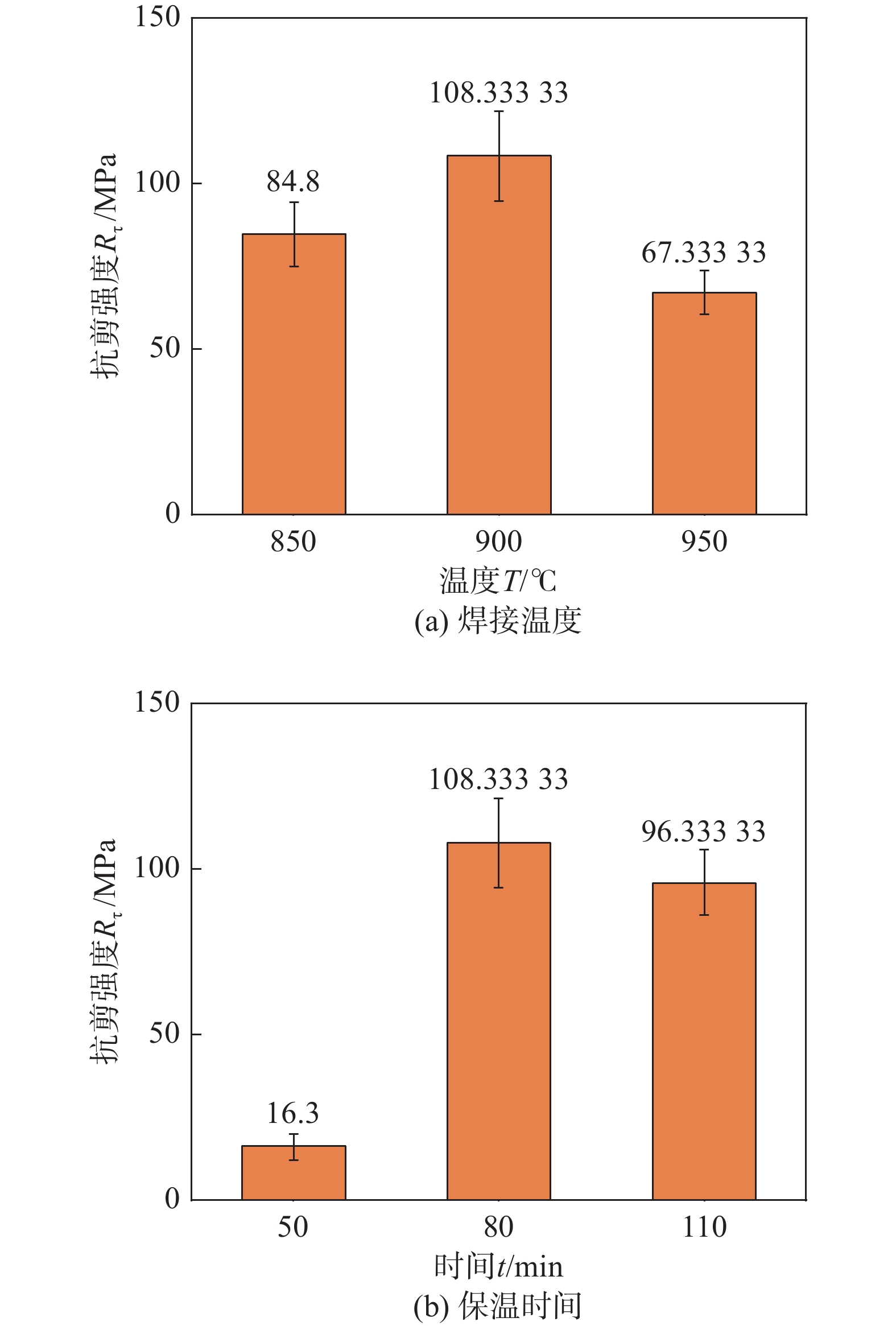
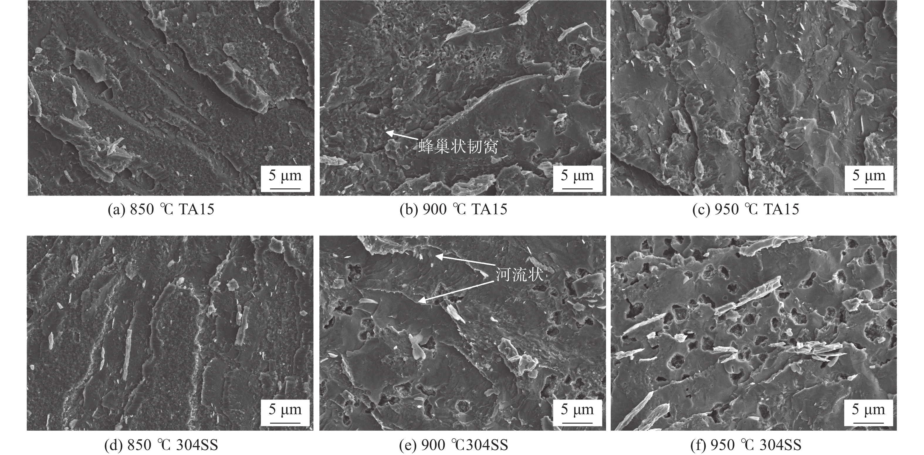
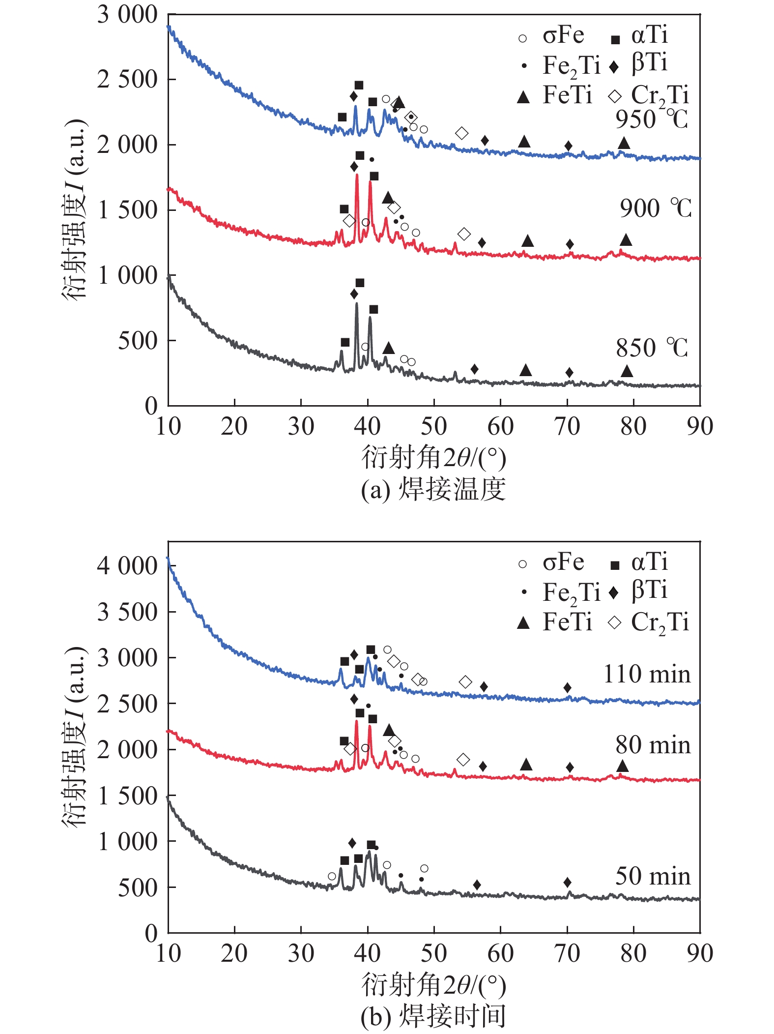
图9为不同焊接参数接头抗剪强度,图9(a)中焊接温度从850 ℃升高到950 ℃,接头的抗剪强度先升高后降低,当焊接温度在900 ℃时,接头强度达到108 MPa,验证了通过改善工艺,促进力学性能的提升,达到相对较好的力学结果. 图10为不同焊接温度下接头压缩剪切断口位置SEM,可以观察到所有试样都是从焊缝处断开,温度为850 ℃时试样断口平整,断裂位置源于接头孔隙处;焊接温度升至900 ℃时,断口形貌层次不齐,由于IMCs的显著增长,断裂位置发生了变化,其断裂位置在第1层(σ-Fe相)和第2层(Fe2Ti + FeTi)发生并向第4层(β-Ti)蔓延;随着温度进一步升至950 ℃时,断裂位置则完整断裂在第1层(σ-Fe相)与第2层(Fe2Ti + FeTi),这是由于温度进一步升高,σ-Fe相与IMCs进一步增多,由于σ-Fe相较脆,在焊接过程中容易引发脆性裂纹,导致大量孔洞和缺口产生. 图11为不同焊接温度下两种材料的接头断口表面形貌,当焊接温度为850 ℃时,TA15和304SS的断口形貌较为平整,有明显平坦河流花样和解理台阶,在断口放大处有光滑小平面,呈现典型沿晶断裂[20],这是典型的脆性断裂特征;当焊接温度升至900 ℃时,TA15和304SS的断口形貌组成较复杂,TA15侧和304SS侧断口既有明显的河流状和解理棱,在局部图中又有部分韧性断裂特征的蜂巢状韧窝存在,这表明焊接接头具有一定的韧性,TA15侧韧窝小但密集,表面有微孔洞分布,304SS侧韧窝大且分布广泛,有较大孔洞分布;当焊接温度进一步升高950 ℃时,TA15侧断口呈现典型脆性特征,蜂巢状韧窝变得更少,表面由解理面和大量光滑平面组成,304SS侧断口形貌为准解理脆性断裂,由解理面及面积较大的光滑平面组成,同时伴随有大量孔洞产生. 根据Kundu等人[21]研究发现在950 ℃下钛钢的扩散速度差异变大,这会导致界面上的元素流动不平衡,由Kirkendall效应形成空隙[22].因此温度的升高有助于元素的扩散,但也可能导致元素扩散系数的差异变大,随着温度升高,304SS侧断口孔洞逐渐增多,这和高温导致的元素扩散差异较大及脆性σ相增多有关. 表5为不同温度下接头TA15侧断口面EDS元素分析,当温度升高至900 ℃,断口表面存在Fe(50.20% ~ 54.17%),Ti(22.33% ~ 33.20%),Cr(8.13% ~ 15.45%)和Ni(4.58% ~ 5.12%),结合断口断裂位置判断,此处区域应含有Fe2Ti,FeTi及Cr2Ti混合物的存在;当温度继续升高至950 ℃,断口表面存在Fe(55.20% ~ 59.05%),Ti(14.20% ~ 20.93%),Cr(16.45% ~ 22.90%)和少量Ni(1.56% ~ 2.33%),与900 ℃断口面元素对比发现,Fe及其Cr元素含量进一步上升,结合断口断裂位置判断,此处区域为Fe2Ti,Cr2Ti和σ-Fe相. 图12为不同焊接参数下TA15侧断口面XRD分析,图12(a)证明了不同温度断口面存在的不同物相,可以发现在850 ℃存在较少分层相,Ti侧断口面多以α-Ti,β-Ti相存在. 在900 ℃下,断口面存在σ-Fe、Fe2Ti、FeTi、Cr2Ti、α-Ti和β-Ti等相,温度升高有助于σ-Fe相的析出,这和断口位置化合物层及TA15侧断口面EDS分析相对应. 当温度升高950 ℃时,Cr2Ti的衍射峰增强,说明更多的Cr原子进入钛合金母材,致使更多的CrTi转化成Cr2Ti,分析存在σ-Fe、Fe2Ti、Cr2Ti、α-Ti和β-Ti等相,这与图10断口面位置及表5断口面EDS对应.
![]() 图 9 不同焊接参数接头抗剪强度Figure 9. Joint shear strength under different welding parameters. (a) welding temperature; (b) welding time
图 9 不同焊接参数接头抗剪强度Figure 9. Joint shear strength under different welding parameters. (a) welding temperature; (b) welding time![]() 图 10 80 min,10 MPa在不同焊接温度的接头断裂位置Figure 10. Fracture location of joints at different welding temperatures of 80 min and 10 MPa. (a) 850 ℃; (b) 900 ℃; (c) 950 ℃
图 10 80 min,10 MPa在不同焊接温度的接头断裂位置Figure 10. Fracture location of joints at different welding temperatures of 80 min and 10 MPa. (a) 850 ℃; (b) 900 ℃; (c) 950 ℃![]() 图 11 80 min和10 MPa在不同焊接温度的接头断口形貌Figure 11. Fracture morphology of joints at different welding temperatures of 80 min and 10 MPa. (a) 850 ℃ TA15; (b) 900 ℃ TA15; (c) 950 ℃ TA15; (d) 850 ℃ 304SS; (e) 900 ℃ 304SS; (f) 950 ℃ 304SS表 5 80 min和10 MPa在不同焊接温度的接头断口面EDS(质量分数,%)Table 5. EDS of joint fracture surface under 80 min and 10 MPa treatment at different welding temperatures
图 11 80 min和10 MPa在不同焊接温度的接头断口形貌Figure 11. Fracture morphology of joints at different welding temperatures of 80 min and 10 MPa. (a) 850 ℃ TA15; (b) 900 ℃ TA15; (c) 950 ℃ TA15; (d) 850 ℃ 304SS; (e) 900 ℃ 304SS; (f) 950 ℃ 304SS表 5 80 min和10 MPa在不同焊接温度的接头断口面EDS(质量分数,%)Table 5. EDS of joint fracture surface under 80 min and 10 MPa treatment at different welding temperatures温度
T/℃元素 Fe Ti Ni Cr 850 45.53 ~ 48.95 27.50 ~ 30.19 3.37 ~ 4.72 9.05 ~ 14.14 900 50.20 ~ 54.17 22.33 ~ 33.20 4.58 ~ 5.12 8.13 ~ 15.45 950 55.20 ~ 59.05 14.20 ~ 20.93 1.56 ~ 2.33 16.45 ~ 22.90 ![]() 图 12 不同焊接参数下的接头TA15侧断口面XRD衍射图Figure 12. XRD diffraction diagram of the fracture surface of the TA15 side of the joint under different welding parameters. (a) welding temperature; (b) welding time
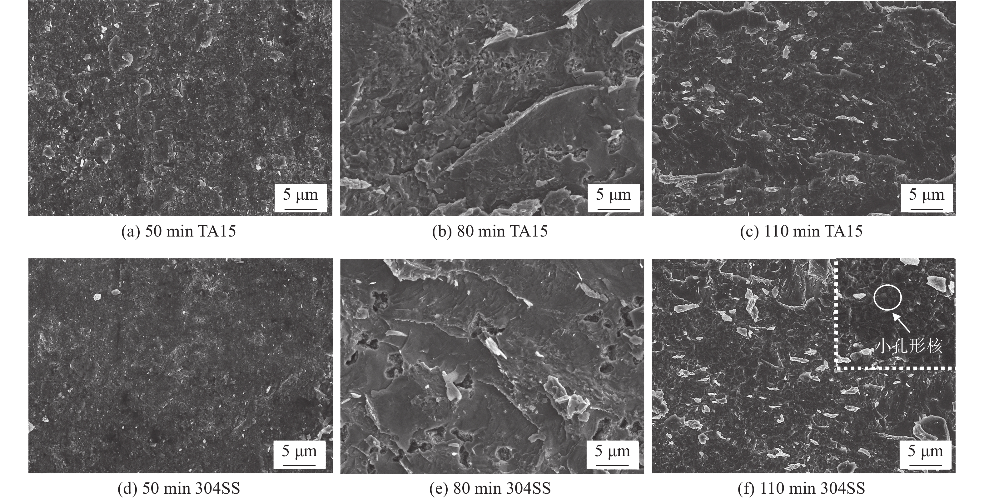
图 12 不同焊接参数下的接头TA15侧断口面XRD衍射图Figure 12. XRD diffraction diagram of the fracture surface of the TA15 side of the joint under different welding parameters. (a) welding temperature; (b) welding time图9(b)为50 ~ 110 min形成的接头抗剪强度,随着焊接时间从50 min升到80 min时,接头抗剪强度明显升高,当时间升至110 min时,抗剪强度小幅度降低,下降比例约为11%,说明保温时间增长到一定时,对接头的剪切性能影响显著减小. 图13为50 ~ 110 min下不同材料的接头断口表面SEM形貌,随着焊接时间从50 min升至110 min,接头断口面从无特征脆性断裂过渡到韧性-脆性混合断裂,在50 min焊接时间下接头断口表面具有无特征的脆性面,存在不规则形状微小空洞,这是由于较低时间导致焊接表面接触不均匀,合金元素的扩散行为非常有限,这也是在50 min下的焊接接头剪切力很低的原因之一. 随着焊接时间升高至80 min及以上时,焊接接触变得充分,当焊接时间升至110 min时,断口形貌发生进一步变化,TA15侧和304SS侧有明显大面积蜂巢状韧窝存在,在断口韧窝表面存在小球状颗粒物,这种颗粒相关研究称之为小孔形核[23],它的形成主要和金属间化合物及其第二相粒子有关,小孔形核会导致接头在此处产生脆性应力集中产生裂纹[24],这对接头的力学性能产生负面影响,进一步说明此接头断口形貌为韧性-脆性混合断裂.表6为不同焊接时间下TA15侧断口面EDS元素分析,随着时间的增长,Fe和Cr含量逐步上升说明元素扩散程度的加深,这也伴随IMCs含量的增多. 当时间提高至110 min,断口表面存在Fe(47.60% ~ 61.06%),Ti(9.34% ~ 38.43%),Cr(9.46% ~ 31.84%)和少量Ni(0% ~ 3.59%),结合元素划分、组织及断口形貌分析,此处区域可能生成了Fe2Ti,FeTi和Cr2Ti化合物. 图12(b)为不同时间下TA15侧断口面XRD分析,证明了不同时间下,断口面存在不同物相. 在焊接时间较低时接头扩散不充分,界面主要以α-Ti,β-Ti相及Fe2Ti为主,当保温时间升高至110 min时,结合断口面EDS分析,由于Cr元素的富集及其保温时间的延长,界面析出了σ-Fe相,这与元素划分形貌组织分析相对应,此外还出现了Fe2Ti,Cr2Ti化合物.
![]() 图 13 900 ℃和10 MPa不同焊接时间接头断口形貌Figure 13. Fracture morphology of joints with different welding times at 900 ℃ and 10 MPa. (a) 50 min TA15; (b) 80 min TA15; (c) 110 min TA15; (d) 50 min 304SS; (e) 80 min 304SS; (f) 110 min 304SS表 6 不同焊接时间在900 ℃和10 MPa断口面EDS(质量分数,%)Table 6. EDS of joint fracture surface under 900 ℃ 10 MPa treatment at different holding times
图 13 900 ℃和10 MPa不同焊接时间接头断口形貌Figure 13. Fracture morphology of joints with different welding times at 900 ℃ and 10 MPa. (a) 50 min TA15; (b) 80 min TA15; (c) 110 min TA15; (d) 50 min 304SS; (e) 80 min 304SS; (f) 110 min 304SS表 6 不同焊接时间在900 ℃和10 MPa断口面EDS(质量分数,%)Table 6. EDS of joint fracture surface under 900 ℃ 10 MPa treatment at different holding times时间
t/min元素 Fe Ti Ni Cr 50 3.48 ~ 20.24 62.57 ~ 79.09 1.93 ~ 11.86 1.19 ~ 1.67 80 50.20 ~ 54.17 22.33 ~ 33.20 4.58 ~ 5.12 8.13 ~ 15.45 110 47.60 ~ 61.06 9.34 ~ 38.43 0 ~ 3.59 9.46 ~ 31.84 综上,在焊接温度或焊接时间较低时,材料表面未能实现紧密结合且元素扩散受到限制,因此接头强度较低. 当焊接温度和时间升高,接头表面的逐步塑形变形促进表面接触紧密和元素相互扩散,形成部分金属间化合物,这使剪切力学性能得到提升. 当焊接温度或时间进一步升高,由于元素扩散系数的差异增大且母材在高温下出现一定软化变形,导致TA15/304SS的焊缝处不紧密,同时脆性化合物分层及σ相较多使剪切性能下降.
3. 结论
(1)接头扩散区域宽度随着焊接温度的提高而增加,随着温度升高,元素扩散更加充分,接头孔洞逐渐减少且观察到逐渐增加的分层产物,经微观结构和元素分析表明,分层产物主要为金属间化合物组成的界面层,即σ-Fe(第1层),FeTi + Fe2Ti(第2层),FeTi + β-Ti(第3层)和β-Ti(第4层).
(2)随着焊接温度升高,焊接接头的抗剪强度呈现先增高后降低的趋势,焊接温度在900 ℃时焊接接头达到最大的108 MPa,且剪切断口形貌呈现典型的脆-韧性混合断裂特征. 在900 ℃焊接参数基础上,随着焊接时间的提升,焊接接头的微观形貌和成分组织与提高焊接温度参数呈现相似规律,出现类似物相产物,增长焊接时间对接头的抗剪强度影响较小,断口出现以韧性为主的脆-韧性混合断裂特征.
-
![]()
图 1 TA15/304SS真空扩散焊接装配示意图
Figure 1. Schematic diagram of TA15/304SS vacuum diffusion welding assembly
![]()
图 2 TA15/304SS真空扩散焊接试样压缩剪切示意图(mm)
Figure 2. Schematic diagram of compression and shear of TA15/304SS vacuum diffusion welding specimens
![]()
图 3 80 min和10 MPa在不同焊接温度的接头金相形貌
Figure 3. Metallographic of joints with different welding temperature at 80 min and 10 MPa. (a) 850 ℃; (b) 900 ℃; (c) 950 ℃
![]()
图 4 900 ℃和10 MPa在不同焊接时间的接头金相形貌
Figure 4. Metallographic of joints with different welding times at 900 ℃ and 10 MPa. (a) 50 min; (b) 80 min; (c) 110 min
![]()
图 5 80 min和10 MPa在不同焊接温度的接头SEM形貌
Figure 5. SEM of joints with different welding temperatures at 80 min and 10 MPa treatment. (a) 850 ℃; (b) 900 ℃; (c) 950 ℃
![]()
图 6 900 ℃和10 MPa在不同焊接时间的接头SEM形貌
Figure 6. SEM of joints with different welding times at 900 ℃ and 10 MPa. (a) 50 min; (b) 80 min; (c) 110 min
![]()
图 7 80 min和10 MPa在不同焊接温度下处理下的接头元素线扫描
Figure 7. Line scan of joint elements at different welding temperatures of 80 min and 10 MPa. (a) 850 ℃; (b) 900 ℃; (c) 950 ℃
![]()
图 8 900 ℃,10 MPa和110 min接头焊缝区元素线扫描
Figure 8. Scanning of elemental lines in the weld seam area at 900 ℃, 10 MPa, and 110 min
![]()
图 9 不同焊接参数接头抗剪强度
Figure 9. Joint shear strength under different welding parameters. (a) welding temperature; (b) welding time
![]()
图 10 80 min,10 MPa在不同焊接温度的接头断裂位置
Figure 10. Fracture location of joints at different welding temperatures of 80 min and 10 MPa. (a) 850 ℃; (b) 900 ℃; (c) 950 ℃
![]()
图 11 80 min和10 MPa在不同焊接温度的接头断口形貌
Figure 11. Fracture morphology of joints at different welding temperatures of 80 min and 10 MPa. (a) 850 ℃ TA15; (b) 900 ℃ TA15; (c) 950 ℃ TA15; (d) 850 ℃ 304SS; (e) 900 ℃ 304SS; (f) 950 ℃ 304SS
![]()
图 12 不同焊接参数下的接头TA15侧断口面XRD衍射图
Figure 12. XRD diffraction diagram of the fracture surface of the TA15 side of the joint under different welding parameters. (a) welding temperature; (b) welding time
![]()
图 13 900 ℃和10 MPa不同焊接时间接头断口形貌
Figure 13. Fracture morphology of joints with different welding times at 900 ℃ and 10 MPa. (a) 50 min TA15; (b) 80 min TA15; (c) 110 min TA15; (d) 50 min 304SS; (e) 80 min 304SS; (f) 110 min 304SS
表 1 TA15化学成分(质量分数,%)
Table 1 Chemical compositions of TA15
Al V Zr Mo Si 杂质 Ti 7.06 1.40 2.06 1.36 0.026 ≤0.3 余量  下载: 导出CSV
表 2 304SS化学成分(质量分数,%)
Table 2 Chemical compositions of 304SS
C Mn P S Cr Si Ni Fe ≤0.08 ≤2.0 ≤0.045 ≤0.03 18.0 ~ 20 ≤0.8 8.0 ~ 11.0 余量
下载: 导出CSV
表 3 图5(c)接头焊缝区元素含量(质量分数,%)
Table 3 Joint weld area element content in Fig 5(c)
层数 Fe Ti Ni Cr Al V 1 69.17 1.32 9.85 19.48 0.11 0.07 2 40.61 42.22 13.39 2.63 0.55 0.60 3 13.72 73.32 3.53 2.39 4.96 2.08 4 10.86 75.71 4.58 1.57 5.35 1.93
下载: 导出CSV
表 4 图6(c)接头焊缝区元素含量(质量分数,%)
Table 4 Joint weld area element content in Fig 6(c)
层数 Fe Ti Ni Cr Al V 1 67.10 1.95 0.79 28.73 0.76 0.67 2 63.47 10.28 0.10 25.13 0.82 0.20 3 39.35 49.25 6.41 2.71 2.04 0.24 4 4.69 69.80 9.88 2.58 7.32 5.73
下载: 导出CSV
表 5 80 min和10 MPa在不同焊接温度的接头断口面EDS(质量分数,%)
Table 5 EDS of joint fracture surface under 80 min and 10 MPa treatment at different welding temperatures
温度
T/℃元素 Fe Ti Ni Cr 850 45.53 ~ 48.95 27.50 ~ 30.19 3.37 ~ 4.72 9.05 ~ 14.14 900 50.20 ~ 54.17 22.33 ~ 33.20 4.58 ~ 5.12 8.13 ~ 15.45 950 55.20 ~ 59.05 14.20 ~ 20.93 1.56 ~ 2.33 16.45 ~ 22.90
下载: 导出CSV
表 6 不同焊接时间在900 ℃和10 MPa断口面EDS(质量分数,%)
Table 6 EDS of joint fracture surface under 900 ℃ 10 MPa treatment at different holding times
时间
t/min元素 Fe Ti Ni Cr 50 3.48 ~ 20.24 62.57 ~ 79.09 1.93 ~ 11.86 1.19 ~ 1.67 80 50.20 ~ 54.17 22.33 ~ 33.20 4.58 ~ 5.12 8.13 ~ 15.45 110 47.60 ~ 61.06 9.34 ~ 38.43 0 ~ 3.59 9.46 ~ 31.84
下载: 导出CSV
-
[1] 李兴无, 沙爱学, 张旺峰, 等. TA15合金及其在飞机结构中的应用前景[J]. 钛工业进展, 2003(Z1): 90 − 94. Li Xingwu, Sha Aixue, Zhang Wangfeng, et al. TA15 alloy and its application prospect in aircraft structure[J]. Progress in Titanium Industry, 2003(Z1): 90 − 94.
[2] El-Egamy S S, Badaway W A. Passivity and passivity breakdown of 304 stainless steel in alkaline sodium sulphate solutions[J]. Journal of Applied Electrochemistry, 2004, 34: 1153 − 1158.
[3] 李宁, 王刚, 王廷, 等. Inconel 718镍基合金与304不锈钢电子束焊接[J]. 焊接学报, 2019, 40(2): 82 − 85. Li Ning, Wang Gang, Wang Ting, et al. Weldability of Inconel 718 and 304 stainless steel by electron beam welding[J]. Transactions of the China Welding Institution, 2019, 40(2): 82 − 85.
[4] Naveen Kumar N, Janaki Ram G D, Bhattacharya S S, et al. Spark plasma welding of austenitic stainless steel AISI 304L to commercially pure titanium[J]. Transactions of the Indian Institute of Metals, 2015, 68: 289 − 297. doi: 10.1007/s12666-015-0589-6
[5] Hao X, Dong H, Li S, et al. Lap joining of TC4 titanium alloy to 304 stainless steel with fillet weld by GTAW using copper-based filler wire[J]. Journal of Materials Processing Technology, 2018, 257: 88 − 100. doi: 10.1016/j.jmatprotec.2018.02.020
[6] 牛小男, 崔丽, 王鹏, 等. 镍铝青铜过渡层对钛合金/不锈钢异种材料激光焊接头组织与力学性能的影响[J]. 焊接学报, 2022, 43(1): 42 − 47. Niu Xiaonan, Cui Li, Wang Peng, et al. Effect of nickel aluminum bronze transition layer on microstructure and mechanical properties of laser welded titanium alloy/stainless steel joint[J]. Transactions of the China Welding Institution, 2022, 43(1): 42 − 47.
[7] Zhao Yongtao, Hu Yuqing, Dong Junhui, et al. The effect of welding materials on 1Cr18Ni9Ti and 2Cr13 steel welded joints electrochemical properties[J]. China Welding, 2022, 31(3): 42 − 47.
[8] 苗玉刚, 林志成, 邹俊攀, 等. 旁路分流电弧钎焊钛/钢异种金属接头特性分析[J]. 焊接学报, 2019, 40(9): 99 − 103. Miao Yugang, Lin Zhicheng, Zou Junpan,et al. Characteristic of titanium/steel dissimilar metals joint brazed by bypass-current arc welding[J]. Transactions of the China Welding Institution, 2019, 40(9): 99 − 103.
[9] Ghosh M, Chatterjee S. Characterization of transition joints of commercially pure titanium to 304 stainless steel[J]. Materials Characterization, 2002, 48(5): 393 − 399. doi: 10.1016/S1044-5803(02)00306-6
[10] Velmurugan C, Senthilkumar V, Sarala S, et al. Low temperature diffusion bonding of Ti-6Al-4V and duplex stainless steel[J]. Journal of Materials Processing Technology, 2016, 234: 272 − 279. doi: 10.1016/j.jmatprotec.2016.03.013
[11] 周荣林, 何鹏, 李小强, 等. 钛合金/不锈钢网的扩散连接[J]. 宇航材料工艺, 1999(1): 46 − 50. doi: 10.3969/j.issn.1007-2330.1999.01.010 Zhou Ronglin, He Peng, Li Xiaoqiang, et al. Diffusion bonding of titanium alloy/stainless steel mesh[J]. Aerospace Materials Technology, 1999(1): 46 − 50. doi: 10.3969/j.issn.1007-2330.1999.01.010
[12] He P, Zhang J H., Li X Q. Diffusion bonding of titanium alloy to stainless steel wire mesh[J]. Materials Science and Technology, 2001, 17(9): 1158 − 1162. doi: 10.1179/026708301101511112
[13] Vigraman T, Ravindran D, Narayanasamy R. Effect of phase transformation and intermetallic compounds on the microstructure and tensile strength properties of diffusion-bonded joints between Ti–6Al–4V and AISI 304L[J]. Materials & Design, 2012, 36(4): 714 − 727.
[14] 高旺旺. TA2/S316扩散焊接头组织与性能研究[D]. 济南: 山东大学, 2020. Gao Wangwang. Study on the structure and properties of TA2/S316 diffusion welded joint [D]. Jinan: Shandong University, 2020.
[15] 李明兵, 王新南, 商国强, 等. 近α型、(α + β)型和近β型钛合金的高温力学性能[J]. 金属热处理, 2022, 47(11): 199 − 205. Li Mingbing, Wang Xinnan, Shang Guoqiang, et al. High temperature mechanical properties of near-α type, (α + β) type and near-β type titanium alloy[J]. Heat Treatment of Metals, 2022, 47(11): 199 − 205.
[16] Nakajima H, Koiwa M. Diffusion in titanium[J]. ISIJ International, 1991, 31(8): 757 − 766. doi: 10.2355/isijinternational.31.757
[17] Mukherjee A B, Laik A, Kain V, et al. Shrinkage-stress assisted diffusion bonds between titanium and stainless steel: a novel technique[J]. Journal of Materials Engineering and Performance, 2016, 25: 4425 − 4436. doi: 10.1007/s11665-016-2284-0
[18] Kumar R R, Gupta R K, Sarkar A, et al. Vacuum diffusion bonding of α-titanium alloy to stainless steel for aerospace applications: Interfacial microstructure and mechanical characteristics[J]. Materials Characterization, 2022, 183: 111607. doi: 10.1016/j.matchar.2021.111607
[19] Zhong Z, Hinoki T, Nozawa T, et al. Microstructure and mechanical properties of diffusion bonded joints between tungsten and F82H steel using a titanium interlayer[J]. Journal of Alloys and Compounds, 2010, 489(2): 545 − 551. doi: 10.1016/j.jallcom.2009.09.105
[20] 姚尚君, 苗鑫, 陈思杰, 等. 焊接温度对钛/钢复合管瞬时液相扩散焊接头组织与性能的影响[J]. 机械工程材料, 2023, 47(2): 33 − 38. doi: 10.11973/jxgccl202302006 Yao Shangjun, Miao Xin, Chen Sijie, et al. Effect of welding temperature on microstructure and properties of instantaneous liquid diffusion welding head of titanium/steel composite pipe[J]. Materials for Mechanical Engineering, 2023, 47(2): 33 − 38. doi: 10.11973/jxgccl202302006
[21] Kundu S, Sam S, Chatterjee S. Evaluation of interface microstructure and mechanical properties of the diffusion bonded joints of Ti–6Al–4V alloy to micro-duplex stainless steel[J]. Materials Science and Engineering:A, 2011, 528(15): 4910 − 4916. doi: 10.1016/j.msea.2011.02.050
[22] 杜正勇, 李宇轩, 刘煜纯, 等. 铜/钢异种金属焊接技术研究现状[J]. 焊接, 2023(9): 1 − 23. Du Zhengyong, Li Yuxuan, Liu Yuchun, et al. Research status of copper/steel dissimilar metal welding[J]. Welding & Joining, 2023(9): 1 − 23.
[23] 钟群鹏, 赵子华. 断口学[M]. 北京: 高等教育出版社, 2006. Zhong Qunpeng, Zhao Zihua. Fracture Science[M]. Beijing: Higher Education Press, 2006.
[24] 郭峰, 李志. 断裂韧度与钢组织性能的关系[J]. 失效分析与预防, 2007, 2(4): 59 − 64. Guo Feng, Li Zhi. Relationship between fracture toughness and steel microstructure[J]. Failure Analysis and Prevention, 2007, 2(4): 59 − 64.
-
期刊类型引用(2)
1. 吴军,张元祥,朱冬冬,李董航,余建平. 激光定向沉积热行为对Inconel 718镍基合金/304不锈钢显微组织和力学性能的影响. 中国激光. 2025(08): 229-240 .  百度学术
百度学术
2. 王梓任,马帅,任强. 曲线顶管内穿钢管运输与原位焊接技术研究. 北京水务. 2024(06): 59-64 . 百度学术
其他类型引用(0)
计量
- 文章访问数: 180
- HTML全文浏览量: 34
- PDF下载量: 52
- 被引次数: 2
