
Research progress and prospect of numerical simulation of deposit morphology control in solid-state cold spray additive manufacturing
-
摘要: 冷喷涂固态增材制造技术因其沉积效率高、喷涂速度快、热影响小等优点,逐渐成为各国研究热点. 但由于沉积原理与目前发展较为成熟的传统激光增材制造技术具有显著不同,沉积体的形貌控制成为了限制其应用的难点. 基于现有的冷喷涂条件对沉积体形貌影响的研究结果,结果表明,数值模拟成为了形貌预测与控制的主要方法. 因此,综述了冷喷涂沉积体形貌预测的不同数值模拟方法,总结了各个方法的特点,最后对冷喷涂沉积体形貌模拟的现存难题及未来发展方向进行了展望.Abstract: Solid-state cold spray additive manufacturing (CSAM) technology has become increasing hot in research among many countries for its high deposition efficiency, fast deposition speed and low thermal effect. Since the deposition method of CSAM is quite different with that of the traditionally laser additive manufacturing , the control of the deposit morphology has become a major task in the application of the technology. Based on the current conditions, numerical simulation methods have been carried out to study the effect of cold spray on the morphology of deposition. The results show that numercial simulation is a good way to predict and control the deposit morphology. In this paper, various simulation methods were proposed to predict the depositon morphology of CSAM and the characteristic of each method were summarized. Finally, challenges at present and prospect of the simulation of CSAM deposit morphology were proposed.
-
0. 序言
增材制造(additive manufacturing, AM),也称3D打印,它结合了计算机辅助设计技术、材料加工和成形技术,利用软件和数控系统,基于数字模型文件快速制造实体物品[1-3]. 增材制造作为一种“自下而上”的制造技术,使过去受传统制造方法限制而无法实现的复杂结构件的制造成为可能. 近年来,增材制造得到了快速发展,在航空、航天、汽车、生物医学等领域得到了广泛应用[4],其中,选区激光熔化、电子束熔化成形和激光烧结成形已经实现了商业化应用.然而,这些技术中使用的高能激光或电子束会熔化材料,导致许多问题,如氧化、晶粒粗大、残余拉应力等,严重影响其实际应用的发展[5].
冷喷涂(cold spraying, CS)作为一种新型的表面涂层技术,20世纪80年代由前苏联科学院西伯利亚分院理论与应用力学研究所发明,自2000年以来受到了越来越广泛的关注[6-9]. 冷喷涂过程中,金属粉末随着送粉气体和加热气体混合,经过专用Laval喷枪,被加速到300 ~ 1500 m/s后撞击在基体上产生剧烈的塑性变形实现颗粒和基体的有效结合.由于喷涂过程温度低于金属熔点,避免了原材料的相变、氧化、分解等问题. 大量研究表明,冷喷涂技术具有沉积效率高、沉积速度快等优点,不仅可以用于制备高性能涂层,而且在零件修复及块材制备方面也有独特的应用[10],因此在2013年前后国际上出现了冷喷涂增材制造(cold spray additive manufacturing, CSAM)的说法[11-13],后进一步称为冷喷涂固态增材制造.
目前,传统的增材制造已经可以实现产品较为精确的形貌控制[14-15],但是CSAM并未像传统增材制造得到广泛应用,其中一个重要原因就是CSAM形貌控制研究的匮乏[16-18]. 基于实际应用中对产品精度和路径规划的需求,研究人员开始尝试解决形貌控制的问题[19-21]. CSAM的难点在于:①冷喷涂的主要结合方式为机械咬合[22-23],喷涂颗粒只有在法向方向上的速度达到或超过临界速度Vcr时才能实现有效沉积[24-26],喷涂角度的改变会引起法向速度的剧烈变化,当喷涂角度小于70°时往往难以实现有效喷涂[27],然而在实际喷涂过程中,非垂直喷涂十分常见,如何根据所需形貌选择合适的喷涂角度是一个亟待解决的难题;②由于冷喷涂过程中颗粒分布的不均匀性,单道沉积体的厚度分布往往是中间厚边缘薄,因此沉积体表面经常会出现波浪状起伏,会引起沉积体性能的各向异性和表面精度的缺失;③传统增材制造对STL文件的切片路径规划并不能满足CSAM工艺过程,需要新的理论支撑和计算结果进行更为有效的路径规划.
CSAM沉积体形貌模拟的研究重点在于单道次喷涂下不同喷涂条件下的沉积体截面形貌拟合,以及复杂喷涂路径下高厚度沉积体形貌预测. 一般情况下,喷涂角度、喷涂距离、喷枪移动速度和基体表面形貌是CSAM形貌控制中最值得研究的方向[28],用于研究CSAM沉积体形貌模拟与控制的数值模拟方法分为“试验法”和“模拟法”两种[29]. 试验法利用大量喷涂数据,分别分析各种喷涂条件的影响,总结喷涂条件与最终形貌的关系,然后再用于指导后续试验.模拟法通过建立合适的模型利用仿真软件数值模拟出最终沉积体形貌,如果预测准确的话就可以用于沉积体形貌控制.具体方法主要有以下4种:高斯法(Gaussian Model, GM)、人工神经网络法(Artificial Neural Network, ANN)、热喷涂工具包法(Thermal Spray Toolkit, TST)和克林科夫法(Klinkov Model, KM).还有一些方法研究较少,如卷积法(Convolution Method)和计算流体动力学法(Computational Fluid Dynamics, CFD)等. 通过对冷喷涂沉积体形貌的有效模拟,可以实现对目标复杂沉积体形状的合理喷涂路径规划,为制造独立成形的冷喷涂固态增材制造提供坚实基础.
1. 冷喷涂增材制造沉积体形貌模拟方法
1.1 高斯法
高斯法基于试验单点喷涂沉积体形貌进行函数拟合与模型假设,选择合适的函数类型和适当的沉积体累积方式,在连续移动喷涂时通过测量沉积体表面的平整度来反应拟合函数的准确性与累积方式的适用性,此模拟过程大多依托MATLAB平台实现.单点喷涂的沉积体形貌拟合函数集中于选择空间对称,如:高斯分布函数、柯西分布函数、β分布函数、抛物线分布函数和椭圆双β分布函数分别为
$$ f(x) = \frac{1}{{\sqrt {2\text{π} } \sigma }}{{\rm{e}}^{ - \tfrac{{{{(x - \mu )}^2}}}{{2{\sigma ^2}}}}} $$ (1) $$ f(x) = \frac{1}{\text{π} }\left[ {\frac{\gamma }{{{{(x - {x_0})}^2} + {\gamma ^2}}}} \right] $$ (2) $$ f(x) = \frac{1}{{B(\alpha ,\beta )}}{x^{\alpha - 1}}{(1 - x)^{\beta - 1}} $$ (3) $$ f(x) = C{\left( {1 - \frac{{4{x^2}}}{{{w^2}}}} \right)^{\beta - 1}} $$ (4) $$ f(x,y) = C{\left( {1 - \frac{{{x^2}}}{{{a^2}}}} \right)^{{\beta _1} - 1}}{\left[ {1 - \frac{{{y^2}}}{{{b^2}{{\left( {1 - \dfrac{{{x^2}}}{{{a^2}}}} \right)}^2}}}} \right]^{{y^{{\beta _2} - 1}}}} $$ (5) 式中:x,y分别为横、纵坐标;μ为均值;σ为标准差;x0为定义分布峰值位置的位置参数;γ,α,β,C,w为形状参数.沉积体累积方式研究重点在于,根据单点沉积形貌选择相邻喷涂道次合适的重叠率,与根据工件形貌进行合适的路径规划.
Chen等人[30]使用高斯法和任意拉格朗日欧拉法(Arbitrary Lagrangian-Eulerian, ALE)研究了沉积体累积模型和瞬时温度变化情况(图1),沉积体累积模型采用考虑了喷枪移动速度、喷涂角度、相邻喷涂道次重叠率的优化后的高斯型分布.为了获得最佳相邻喷涂道次重叠率,施栩等人[31]使用牛顿迭代法,使得涂层厚度最大值和最小值的差值最小;王战中等人[32]在加入修正系数后得出喷涂轨迹重叠率在58.6%时沉积体表面最均匀;吴洪键等人[33]则假定轮廓拟合函数的二阶导数为零,此时重叠率约为66.7%. 董慧芬和冯浩等人[34-35]运用极坐标对球面喷涂进行了研究,同时使用遗传算法进行修正,为有限区域曲面喷涂提供了有效的仿真思路,霍平等人[36]也运用相似的解法在复杂曲面上得出一致结果.
![]() 图 1 喷涂时瞬时沉积体形貌与温度分布[30]Figure 1. Transient deposits profile and temperature distribution. (a) t = 3 s; (b) t = 6 s; (c) t = 8 s; (d) t = 9.6 s; (e) t = 14.6 s; (f) t = 33 s
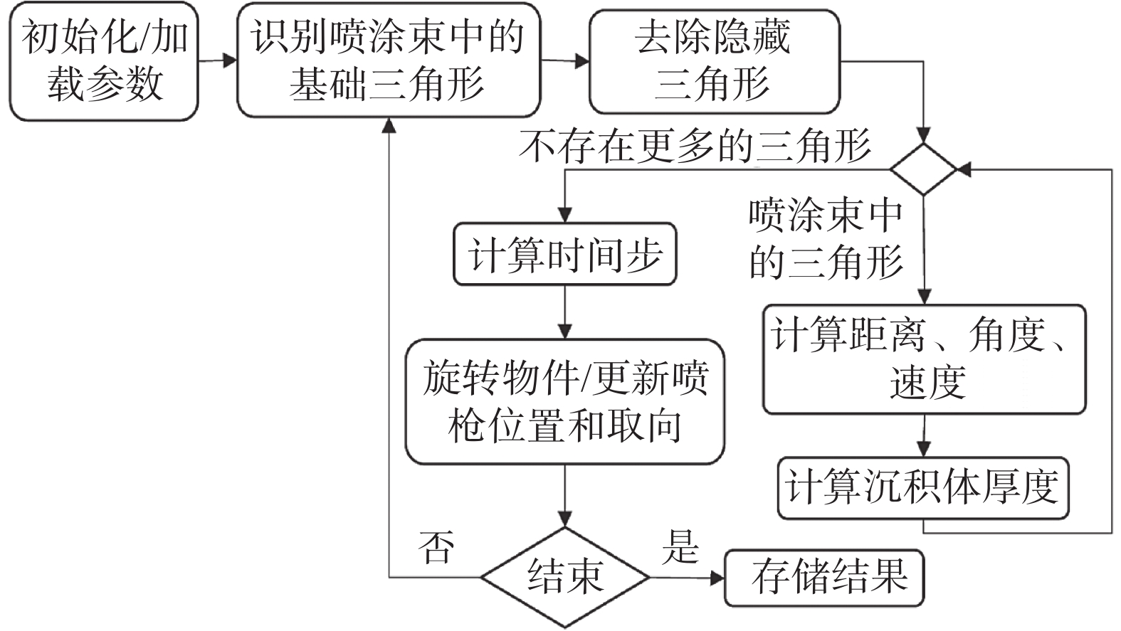
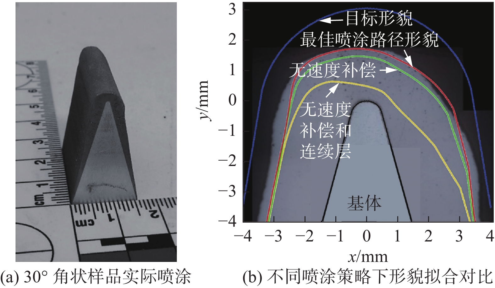
图 1 喷涂时瞬时沉积体形貌与温度分布[30]Figure 1. Transient deposits profile and temperature distribution. (a) t = 3 s; (b) t = 6 s; (c) t = 8 s; (d) t = 9.6 s; (e) t = 14.6 s; (f) t = 33 sDuncan等人[37]通过抽样理论把喷涂路径规划问题转化成为空间频域,并证明倾斜光栅图案也可以形成连续的路径,当喷涂颗粒的分布改变时此种方法较为适用. Tzinava等人[38]基于MATLAB平台编程出一款适用范围广泛的喷涂模拟器,算法运用目前增材制造三维模型的STL文件保存模型的顶点与位矢信息,分别计算STL文件中每个表面三角形法向量和喷枪位置向量的关系来实现表面沉积判断,算法流程如图2所示,其中使用的拟合函数为高斯分布函数,同时可以实现喷涂路径中遮挡物的有效判断,初步为表面修复提供有效依据.Nault等人[39]假设冷喷涂沉积体为层层连续沉积形成,并使用速度补偿对基体表面曲率改变时的沉积体厚度进行修正,实现了任意凸起表面的沉积,如图3所示,优化后的沉积体形貌明显与实际喷涂效果更加接近.
![]() 图 3 凸起表面基体沉积[39]Figure 3. Deposits on substrate convex angle. (a) deposits on substrate with 30° corner; (b) comparison of deposits profile under different spraying strategies
图 3 凸起表面基体沉积[39]Figure 3. Deposits on substrate convex angle. (a) deposits on substrate with 30° corner; (b) comparison of deposits profile under different spraying strategies高斯法的优势在于对于沉积体表面形貌模拟非常直接,并且在试验数据拟合的基础上可以达到99%的准确性,不需要进行复杂的理论推导,且操作简单,但是其缺点则更为明显.首先,在实际喷涂过程中,连续移动喷涂的沉积体形貌应由单点喷涂积分而来或推导而来,但是在实际研究中常常将单点喷涂的形貌和连续移动喷涂的沉积体形貌混淆,并且由于沉积效率在喷涂过程中会发生剧烈改变,更加大了实际形貌与模拟形貌的差异;其次,对于相邻喷涂道次重叠率优化研究的准确性存疑,先喷涂的沉积体会影响后续喷涂的基体表面形貌,但是冷喷涂的沉积效果对于基体表面形貌十分敏感,因此单纯的将两个喷涂道次叠加并不合适,而且缺少试验验证;最后,高斯法并不能描述沉积体形貌演变情况,特别是出现非对称的形貌轮廓时,难以用函数进行拟合.由于以上缺点的存在,使得高斯法对于冷喷涂沉积体形貌模拟的准确性存在先天不足,然而由于其简单易操作,喷涂路径规划的模拟与优化往往会选择高斯法作为沉积体形貌的试验算法,大大提高了计算效率.
1.2 人工神经网络法
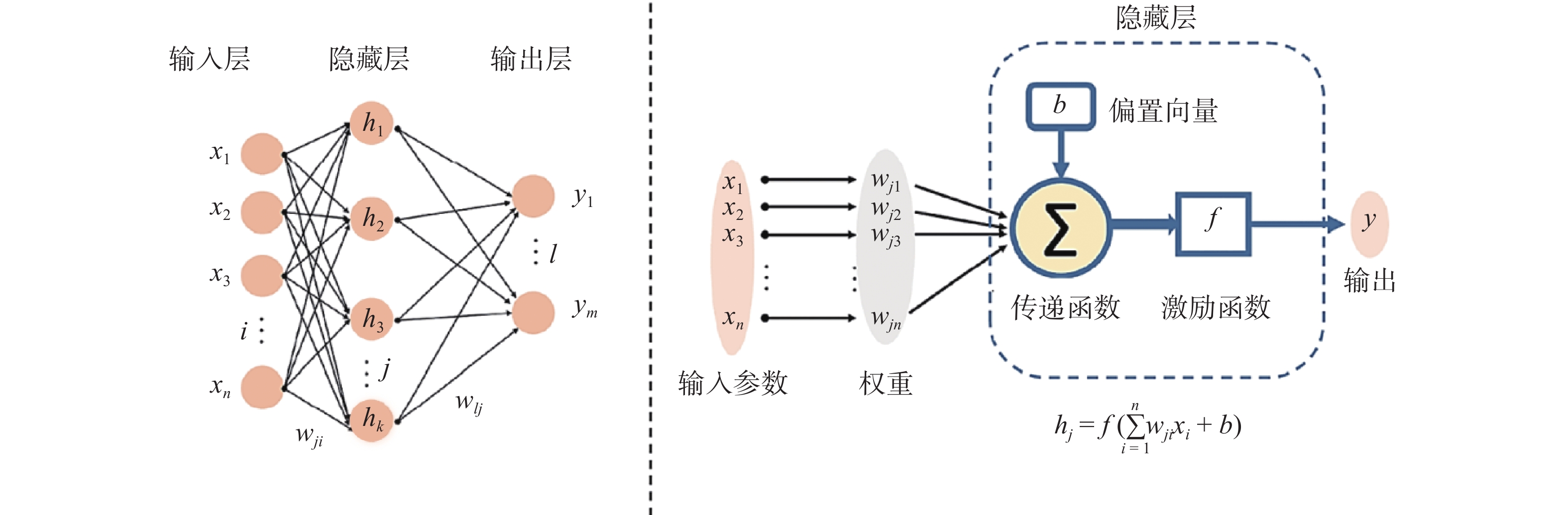
ANN是由大量神经元相互连接而成的运算模型,通过模拟神经元信息传递的方式来反应不同影响因素对最终结果的影响水平,在面对非线性运算的预测具有独特优势. ANN通常分为以下3个层次:输入层、隐藏层和输出层,如图4所示[40],其中xn为输入向量的各个分量,hk为隐藏层的神经元,ym为输出向量的各个分量,wjn为权重,b为偏置向量,f为激励函数,每个神经元代表一个特定的输出函数(激励函数),由不同权重连接. 对于冷喷涂而言,通过改变不同喷涂条件的权重与迭代次数,使模拟结果与实际喷涂收集到的数据相符,可以直观地反映各喷涂条件的影响水平,并在条件改变时对沉积体形貌进行预测.
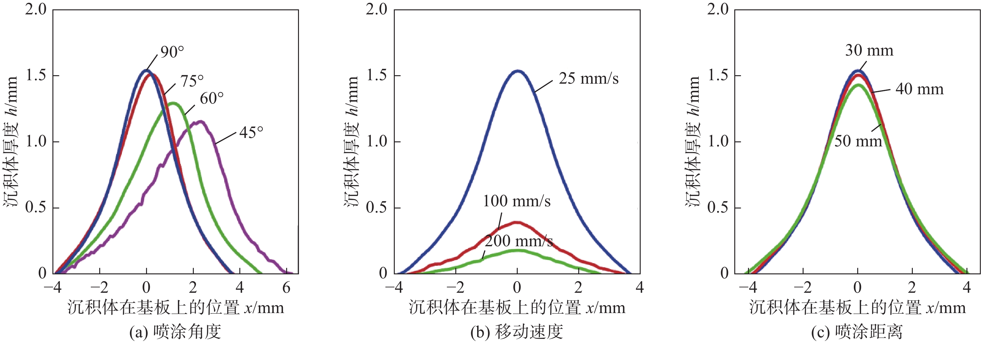
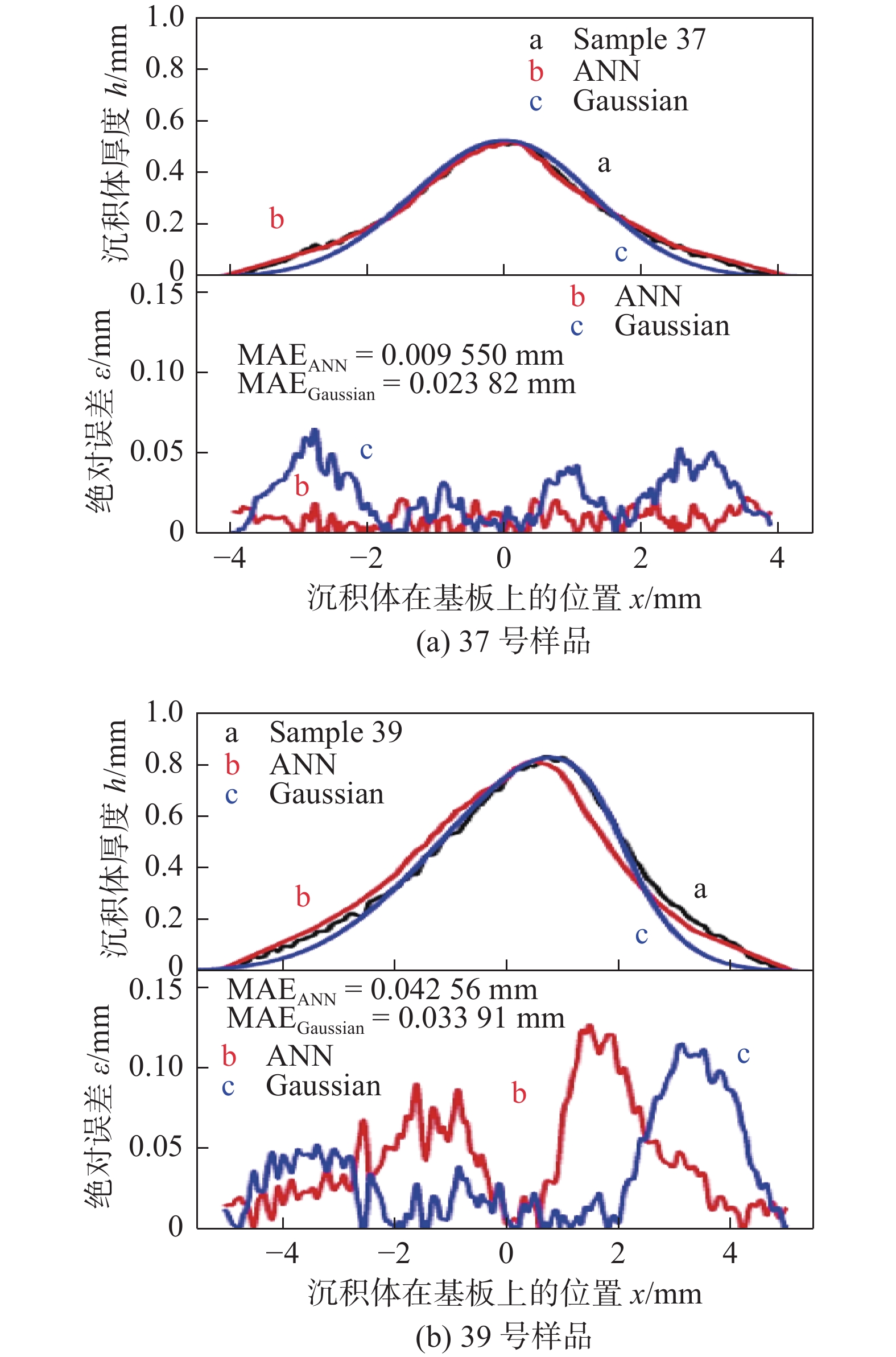
Ikeuchi等人[41-42]首先将ANN应用到冷喷涂沉积体形貌的预测中,并成功地模拟出了喷涂角度、喷枪移动速度和喷涂距离的影响,以不同喷涂条件的沉积体形貌轮廓作为原始数据库(即输入层),如图5所示. 当喷涂角度86°、喷涂速度75 mm/s、喷涂距离45 mm 时37号样品和当喷涂角度48°、喷涂速度34 mm/s、喷涂距离41 mm时39号样品的输出结果如图6所示,其中黑色线条为实际喷涂沉积体轮廓形貌,红色线条为ANN法模拟出的沉积体轮廓形貌,与高斯法的蓝色线条相比,ANN更能够对喷涂轨迹进行有效预测,特别在边缘区域的预测更为贴近实际形貌,在喷涂角度改变时会更加明显,有效展现出ANN方法在对非对称轮廓形貌预测的先进性,且相关系数R2 = 0.9493,展现出足够的有效性与稳定性.
![]() 图 5 不同喷涂条件对沉积体形貌的影响[42]Figure 5. Influence of different spraying conditions on the profile of deposit. (a) spraying angle; (b) traversing speed; (c) standoff distance
图 5 不同喷涂条件对沉积体形貌的影响[42]Figure 5. Influence of different spraying conditions on the profile of deposit. (a) spraying angle; (b) traversing speed; (c) standoff distance![]() 图 6 不同喷涂条件下沉积体实际形貌与人工神经网络法及高斯法模拟形貌对比[42]Figure 6. Comparison of deposits profile between ANN method and Gaussian Model under different spraying conditions. (a) sample 37; (b) sample 39
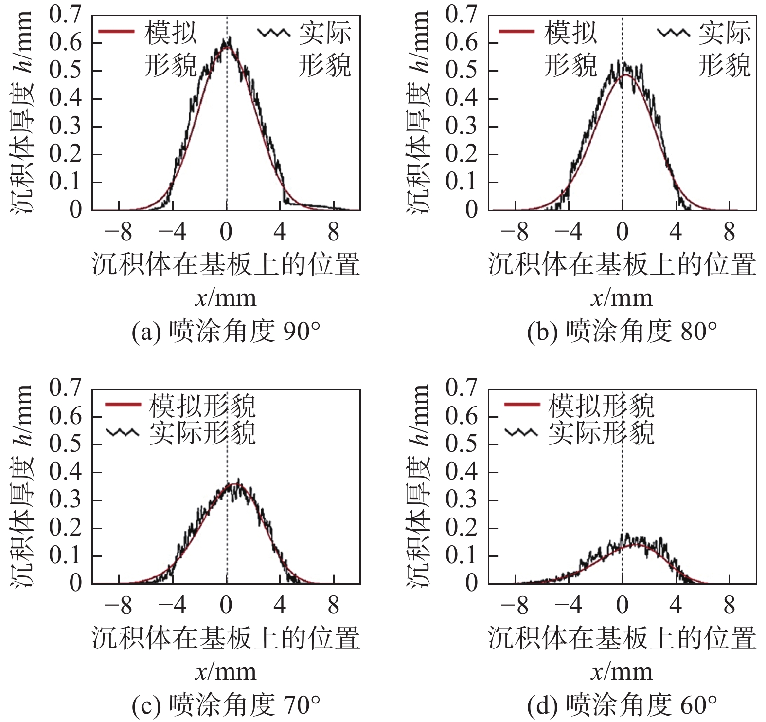
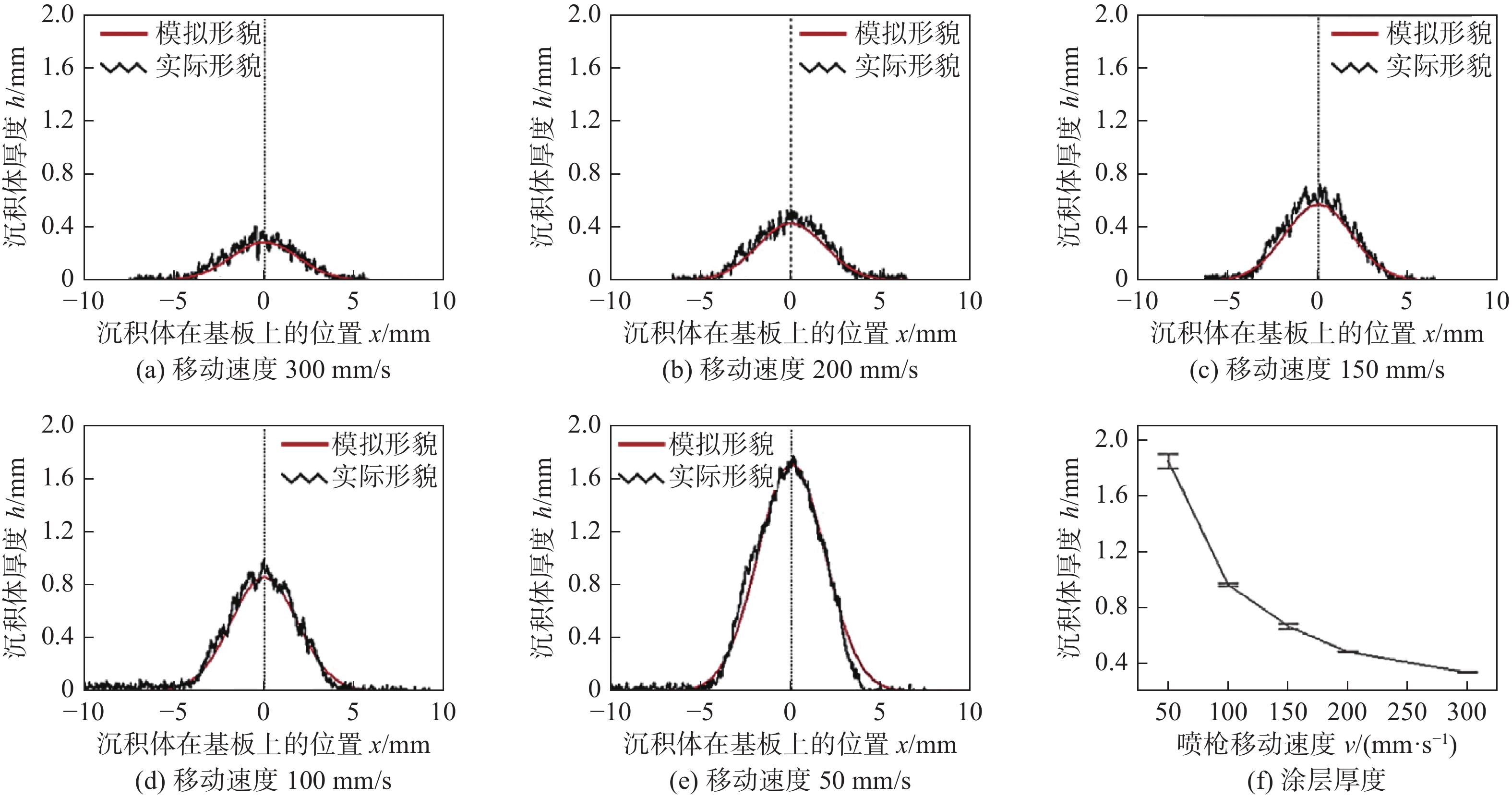
图 6 不同喷涂条件下沉积体实际形貌与人工神经网络法及高斯法模拟形貌对比[42]Figure 6. Comparison of deposits profile between ANN method and Gaussian Model under different spraying conditions. (a) sample 37; (b) sample 39得益于人工智能的快速发展,在证明了ANN法的可行性后,后续对ANN的研究中,学者们倾向于优化隐藏层对数据的处理方式,通常有两种优化方向:提高数据的利用效率和算法优化. 对于提高数据的利用效率,即使得输入层数据的利用更加合理,如Mahapatra等人[43]利用反向传播算法(Back Propagation Algorithm)对脉冲激光粉末沉积的非线性多元沉积过程进行了有效模拟,Xiong等人[44]使用二阶回归模型(Second-Order Regression Model)对丝材电弧增材制造过程进行了模拟,结果表明,通过对原始输入层数据利用的优化可获得更加准确的结果. Chen等人[45]通过结合高斯法,加入拟合沉积效率函数来提高输入层数据的利用效率,有效研究了喷涂角度和喷枪移动速度对沉积体形貌的影响,结果表明,随着喷涂角度由垂直转向非垂直,厚度最高点出现了明显的偏移,并且沉积效率逐渐下降,整体厚度出现逐渐降低的趋势,如图7所示. 而随着喷枪移动速度的增加,整体厚度同样出现逐渐降低的趋势,但厚度最高点并不会出现偏移,如图8所示. Ikeuchi等人[41]证明除了喷涂角度和喷枪移动速度外,喷涂距离仍然适用于此方法,并且发现ANN法和高斯法的复合方法具有更高的精度.对于算法优化,董一萱等人[46]将海洋捕食者算法(Marine Predators Algorithm, MPA)结合ANN方法,通过建立与ANN方法的并行架构,对ANN模型隐藏层中的权重和阈值进行优化,在降低了迭代次数,大大提高运行速度和运行效率的同时,最终运算结果相关系数达到0.9986,证明MPA-ANN方法对于冷喷涂沉积形貌预测具有更佳的准确性.
![]() 图 7 不同喷涂角度下单点沉积体形貌轮廓试验结果与ANN方法模拟结果对比[45]Figure 7. Profile comparison of single spot spraying deposit between experiments and ANN method at different spray angles. (a) spraying angle of 90°; (b) spraying angle of 80°; (c) spraying angle of 70°; (d) spraying angle of 60°
图 7 不同喷涂角度下单点沉积体形貌轮廓试验结果与ANN方法模拟结果对比[45]Figure 7. Profile comparison of single spot spraying deposit between experiments and ANN method at different spray angles. (a) spraying angle of 90°; (b) spraying angle of 80°; (c) spraying angle of 70°; (d) spraying angle of 60°![]() 图 8 不同喷枪移动速度单道沉积体形貌轮廓实验结果与ANN方法模拟结果对比[45]Figure 8. Comparison of deposits profile between experiments and ANN method under different traversing speed. (a) traversing speed 300 mm/s; (b) traversing speed 200 mm/s; (c) traversing speed 150 mm/s; (d) traversing speed 100 mm/s; (e) traversing speed 50 mm/s; (f) deposits thickness
图 8 不同喷枪移动速度单道沉积体形貌轮廓实验结果与ANN方法模拟结果对比[45]Figure 8. Comparison of deposits profile between experiments and ANN method under different traversing speed. (a) traversing speed 300 mm/s; (b) traversing speed 200 mm/s; (c) traversing speed 150 mm/s; (d) traversing speed 100 mm/s; (e) traversing speed 50 mm/s; (f) deposits thicknessANN方法的优势在于结果导向,操作逻辑较为简单,不需要对具体喷涂过程进行较为复杂的研究,研究的重点在于如何提高数据利用效率和优化算法以获得更优的结果,第二是可以有效模拟出喷涂过程中沉积体形貌的演变过程.劣势在于,首先,在使用ANN方法前需要收集足够的样本数据,会耗费大量的工作,Liu等人[47]通过测量实时形貌作为新的样本数据填充到数据库之中,大大的扩充了样本数据量,然而仍旧不能解决样本数据难以收集的问题;其次,在增材制造应用中,立体成形十分常见,而三维形貌模拟势必是发展的重点,而ANN模型只对输出二维模拟结果较为有效;此外,神经网络模型的另一个劣势是缺乏合适的物理基础,因此,当实际喷涂时出现遮挡物,或者需要对喷涂路径进行规划时,ANN法无法进行有效处理;最后,目前的算法容易陷入局部最优解,仍需优化.
1.3 热喷涂工具包法
热喷涂工具包法是基于ABB公司发布的RobotStudioTM平台,用C#语言开发的插件工具包,本身分为3个模块:路径工具包(PathKit)、形貌工具包(ProfileKit)和监控工具包(MonitorKit)[48-49]. PathKit依托RobotStudioTM平台强大的机器人仿真能力,用于对喷涂路径进行规划和仿真,ProfileKit用于对喷涂沉积体形貌仿真,MonitorKit则是对喷涂轨迹进行实时监控.一般情况下,在ProfileKit中通过改变沉积体形貌的物理模型可以获得不同的沉积体形貌,后续学者对TST方法的研究也大多集中于对此模块的优化.
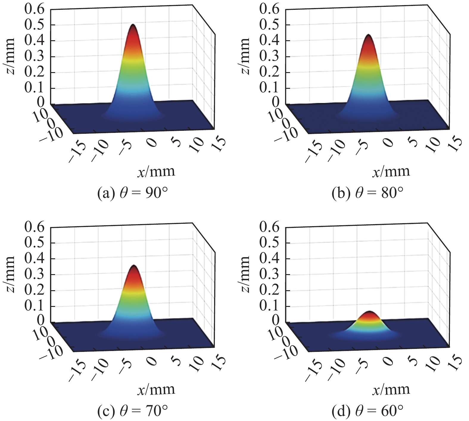
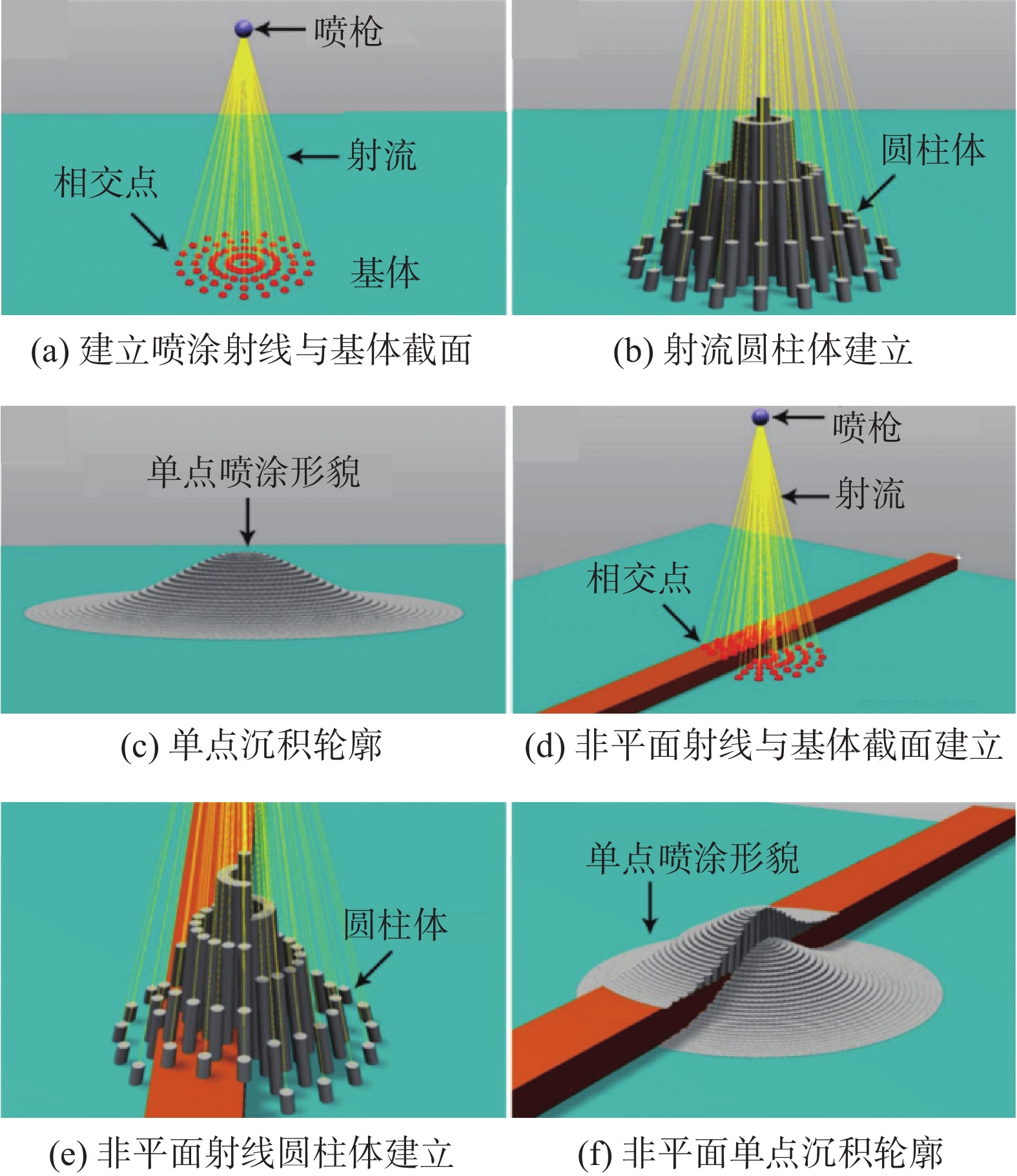
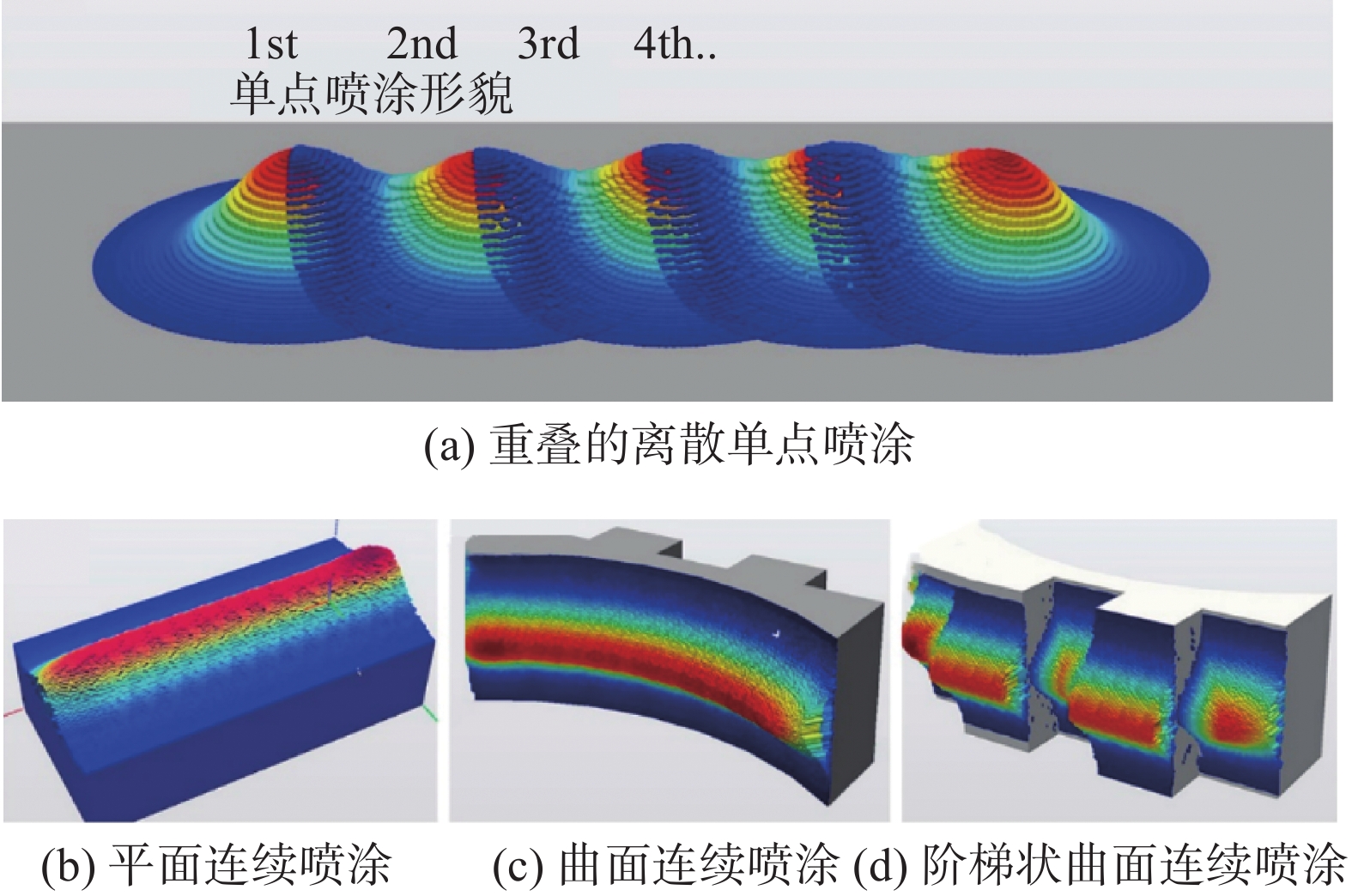
TST方法原本是为热喷涂而设计的,如Deng等人[50]利用TST工具包在复杂曲面上应用机器人离线编程实现热喷涂仿真,Cai等人[51]首次将该方法应用于冷喷涂沉积体形貌的预测,并提出除了单点喷涂沉积体形貌的影响因素,如:喷涂角度、喷涂距离、基体特点等,会影响连续移动喷涂时的沉积体形貌,同时喷涂机器人运动学参数如:喷枪移动速度,喷涂路径规划也具有重要影响,成功在2D条件下,总结出喷涂路径规划和喷涂距离对沉积体表面平整度的影响. 目前TST方法在研究方向集中于实现沉积体形貌的三维仿真,实际喷涂过程仿真(如喷涂路径出现遮挡)以及沉积体形貌控制与优化. Chen等人[45]将TST方法从2D拓展到3D,成功模拟出喷涂角度对对沉积体形貌的影响,如图9所示,当喷涂角度开始减小,厚度分布出现偏移,沉积效率下降,并在试验中得到了验证,除此之外,Chen等人[45]还对沉积体表面平整度进行了模拟研究,结果表明当相邻喷涂道次重叠率减小时,能有效提高沉积体表面平整度.Wu等人[18]通过对单点喷涂的轮廓进行高斯分布拟合并进行分块化处理(图10),实现了复杂曲面的喷涂,如图11所示. 另外,当喷涂路径出现遮挡物后,运用此方法也可以实现有效模拟,使得TST方法能够在复杂的阶梯表面,当存在阴影遮挡效应时准确预测冷喷涂沉积体形貌的演变,如图12所示.
![]() 图 9 不同喷涂角度沉积体形貌3D模拟[45]Figure 9. 3D simulation of single spot deposit profile at different spray angles. (a) θ = 90°; (b) θ = 80°; (c) θ = 70°; (d) θ = 60°
图 9 不同喷涂角度沉积体形貌3D模拟[45]Figure 9. 3D simulation of single spot deposit profile at different spray angles. (a) θ = 90°; (b) θ = 80°; (c) θ = 70°; (d) θ = 60°![]() 图 10 沉积形貌预测流程[18]Figure 10. Schematic diagram of depositing process. (a) planar creation of rays and intersection; (b) planar creation of cylinders; (c) planar single deposit profile; (d) non-planar creation of rays and intersection; (e) non-planar creation of cylinders; (f) non-planar single deposit profile
图 10 沉积形貌预测流程[18]Figure 10. Schematic diagram of depositing process. (a) planar creation of rays and intersection; (b) planar creation of cylinders; (c) planar single deposit profile; (d) non-planar creation of rays and intersection; (e) non-planar creation of cylinders; (f) non-planar single deposit profile![]() 图 11 复杂曲面冷喷涂[18]Figure 11. Complex surface spraying. (a) discrete single deposit profile while overlapping; (b) continuous single deposit profile on flat surface; (c) continuous single deposit profile on curved surface; (d) continuous single deposit profile on complex stair surface
图 11 复杂曲面冷喷涂[18]Figure 11. Complex surface spraying. (a) discrete single deposit profile while overlapping; (b) continuous single deposit profile on flat surface; (c) continuous single deposit profile on curved surface; (d) continuous single deposit profile on complex stair surface![]() 图 12 阶梯状连续冷喷涂[18]Figure 12. Continuous deposition on stair-like substrate with shadow effect. (a) actual profile; (b) simulation profile
图 12 阶梯状连续冷喷涂[18]Figure 12. Continuous deposition on stair-like substrate with shadow effect. (a) actual profile; (b) simulation profileTST方法的优点如下:①在于能够对整个喷涂过程进行有效仿真,特别是对于喷涂机器人运动学参数监控十分有效,使得仿真过程更加贴近实际喷涂过程;②ProfileKit模块是基于合适的物理模型,因此相比较于ANN方法,TST方法的适用性更强;③TST方法能够实现3D模拟,可以更加直观的展示沉积体形貌,而其它方法目前则大多为2D或者准3D的.TST方法的缺点:①由于提前对单点喷涂沉积体形貌进行了函数拟合和假设,因此,缺乏足够的实验验证,准确性不如ANN方法,并且对于非对称分布的轮廓形貌无法处理;②在于TST方法的平台局限性,其只能在RobotStudioTM平台实现,学者对于后续的优化以及编程开发会十分困难.
1.4 克林科夫法
从本质上讲,克林科夫法是在平面冷喷涂过程中的数学推导模型,成功地从解析方面描述了喷涂沉积体形貌随喷涂角度变化的规律. Klinkov等人[52-53]认为喷涂角度是沉积效率最大的影响因素,因此可以把沉积效率看作以喷涂角度为自变量的函数,更准确一些,沉积体的厚度增长速率是沉积体表面的斜率和颗粒分布的函数,即
$$ \frac{{\partial y}}{{\partial t}} = ag\left( {\frac{{\partial y}}{{\partial x}}} \right)h(x,{x_0}) $$ (6) 式中:
$y$ 为沉积体厚度;$t$ 为时间;$a$ 为系数;$g\left( {{{\partial y} \mathord{\left/ {\vphantom {{\partial y} {\partial x}}} \right. } {\partial x}}} \right)$ 为关于涂层斜率的函数;$h\left( {x,x_0} \right)$ 为颗粒分布函数. 当颗粒分布为高斯分布时,通过微分方程求解.$$ {{DE}}(\tan\varphi ) = \left\{ \begin{array}{l} \frac{{{{\rm{e}}^{ - k{{\left( {\dfrac{{\tan\varphi }}{{\tan{\varphi _m}}}} \right)}^2} - {{\rm{e}}^{ - k}}}}}}{{1 - {{\rm{e}}^{ - k}}}},\tan\varphi < \tan{\varphi _m} \\ 0{\text{ }},\tan\varphi \geqslant \tan{\varphi _m} \end{array} \right. $$ (7) 式中:
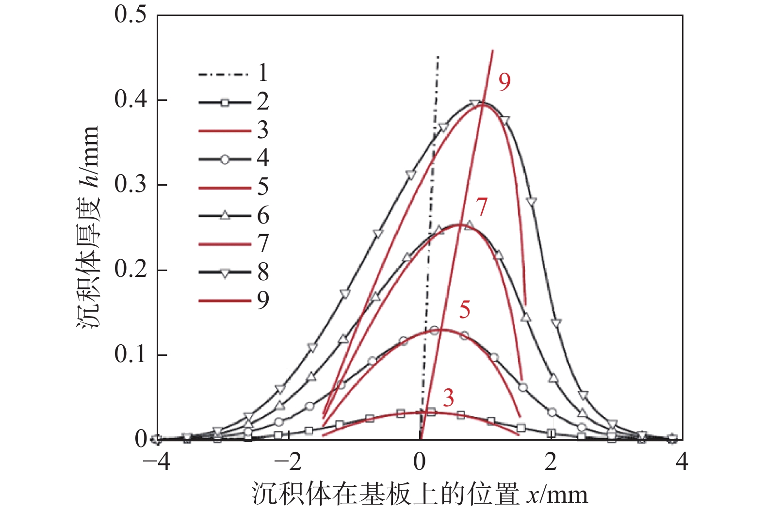
${{DE}}$ 为沉积效率函数;$\tan\varphi = \partial y/\partial x$ ,${\varphi _m}$ = 50°为临界沉积角度,此时$\tan{\varphi _m} = 1.2$ ,$k = 4.5$ 为通过试验测量的公认经验系数. 此方法给出了平面喷涂的二维解析解,结果显示随着喷涂角度的改变,沉积体厚度分布产生了明显倾斜,数值解与解析解相统一,如图13所示,初始轮廓为高斯型分布的数值解(黑色),初始轮廓为抛物线分布的解析解(红色),其中1为喷枪方向. Klinkov等人[52-53]也利用这一结果为增材制造提供了路径规划的思路,如:对于垂直墙壁的增材制造可以首先在基体上垂直喷涂,之后倾斜喷枪分别在沉积体的侧面进行倾斜喷涂,以此循环可实现薄壁的有效沉积.克林科夫法从数学建模的角度出发,给出了冷喷涂沉积过程的解析解,具有很强的物理基础. 尽管该模型足够严谨,但其缺点限制了此方法的广泛应用.首先,基体表面必须为平面. 当喷嘴与喷涂表面之间存在遮挡时,阴影遮挡效应的存在使得克林科夫法无法应用. 其次,克林科夫法的推导是建立在颗粒分布为高斯分布的基础上,求解过程使用的函数简化技巧对其他分布情况难以适用.由于这些原因,克林科夫法大多被认为是冷喷涂沉积形貌演化过程的数学或物理推导模型,可以为其他的模拟方法提供理论基础. 如Vanerio等人[54]以克林科夫法为推导基础,有效地模拟了冷喷涂沉积过程中沉积体准3D形貌的演变过程,分别实现了喷涂沉积次数、喷涂距离、喷枪移动速度、基体表面形状对沉积体形貌的影响,并且克服了在非平面基板上无法实现阴影遮挡效应的难点,如图14所示.
![]() 图 14 阴影遮挡效应的实现[54]Figure 14. Shadow effect. (a) geometric shape of the substrate; (b) schematic diagram of spraying; (c) comparison of profile after 20 passes; (d) cross-sectional view after 20 passes; (e) side view of deposits; (f) profile of deposits
图 14 阴影遮挡效应的实现[54]Figure 14. Shadow effect. (a) geometric shape of the substrate; (b) schematic diagram of spraying; (c) comparison of profile after 20 passes; (d) cross-sectional view after 20 passes; (e) side view of deposits; (f) profile of deposits1.5 不同形貌模拟方法对比
高斯法的优势在于计算方法简洁高效,常常作为其它方法的沉积体轮廓假设基础,大大提高了计算效率,但是由于高斯法的研究基础是基于理想条件下,因此面对形貌演变、复杂曲面喷涂和非空间对称的颗粒分布情况则较为受限,同时局限于2D模拟很能推广到3D. ANN方法以大量的试验数据为基础,具有十分强大的准确性与数据支撑,然而物理模型的缺失使得此方法拓展到不同应用情况时十分困难,而且同样不能进行3D模拟. TST方法在喷涂时充分考虑了喷涂机器人动态参数,有效反应了实际喷涂情况,可以实现复杂曲面的喷涂和3D仿真,但是编程的困难与平台的制约导致了目前的轮廓假设仅限于高斯型分布,需要后续对ProfileKit模块更详细的拓展. 克林科夫法作为一种解析方法,以物理建模为根本详细的揭示形貌演变情况,但是求解的困难阻碍了复杂曲面喷涂和非高斯型分布的应用.表1总结了各方法的特点.
表 1 不同方法特点对比Table 1. Comparison of characteristics of different methods特点 高斯法 ANN TST 克林科夫法 3D — — √ — 物理模型 √ — — √ 复杂曲面喷涂 — — √ — 形貌演变 — — √ √ 数据支撑 √ √ — — 试验验证 — √ √ √ 非空间对称颗粒分布 — — — — 2. 结束语
作为新型增材制造技术,冷喷涂固态增材制造已经逐步成为研究热点,基于实际应用中对形貌控制的需求,沉积体形貌模拟研究正在蓬勃发展,并通过多种方法或模型实现了有效的仿真和预测.目前,不同学者重点研究了喷涂角度、喷涂距离、喷枪移动速度、基体表面形貌这4个影响因素,此外也根据实际冷喷涂的限制要求,实现了喷涂时遮挡物的有效识别,为合理的喷涂路径规划提供理论依据.在未来的发展中,仍有以下挑战需要深入探索.
(1) 目前的所有方法都必须假设喷涂颗粒分布作为起始条件.试验结果表明,在沉积层数较少的情况下,选择不同的颗粒分布函数没有显著差异.然而,当沉积层数足够大时,就会出现明显的差异,其中一些开始与实际情况产生明显偏差.而且,选择合理的颗粒分布的原则尚未确定,如何避免理想状态下的颗粒分布假设是亟待解决的问题.
(2) 大量学者已经对沉积体形貌预测的精度进行了研究,但对形貌演变的终止条件没有给出明确定义.在实际冷喷涂过程中,临界速度的存在及影响因素多导致喷涂颗粒无法实现无限沉积,而模拟仿真方面对此没有限制,势必影响最终结果的准确性.
(3) 单点喷涂和连续移动喷涂之间的关系不明确.从喷涂原理来看,连续移动喷涂的形貌应由单点喷涂推导得出,但目前的研究常常将单点喷涂形貌和连续移动喷涂形貌相混淆.此外,受相邻喷涂道次重叠率的影响,对于减弱或消除沉积体表面波浪状起伏的模拟的准确性,尚未得到有效验证.
(4) 根据沉积体形貌的模拟结果对于喷涂路径规划并未有详细的研究.冷喷涂路径规划仍处于定性研究的阶段,虽然一些研究已经制备出了薄壁或规则形状的沉积体,但是对于典型问题的研究还未形成解决方法的共识,如:直角转弯的优化,沉积体边缘效应损失的补偿等.形成喷涂路径规划的原则将对冷喷涂增材制造的推广应用具有深远意义.
-
![]()
图 1 喷涂时瞬时沉积体形貌与温度分布[30]
Figure 1. Transient deposits profile and temperature distribution. (a) t = 3 s; (b) t = 6 s; (c) t = 8 s; (d) t = 9.6 s; (e) t = 14.6 s; (f) t = 33 s
![]()
图 3 凸起表面基体沉积[39]
Figure 3. Deposits on substrate convex angle. (a) deposits on substrate with 30° corner; (b) comparison of deposits profile under different spraying strategies
![]()
图 5 不同喷涂条件对沉积体形貌的影响[42]
Figure 5. Influence of different spraying conditions on the profile of deposit. (a) spraying angle; (b) traversing speed; (c) standoff distance
![]()
图 6 不同喷涂条件下沉积体实际形貌与人工神经网络法及高斯法模拟形貌对比[42]
Figure 6. Comparison of deposits profile between ANN method and Gaussian Model under different spraying conditions. (a) sample 37; (b) sample 39
![]()
图 7 不同喷涂角度下单点沉积体形貌轮廓试验结果与ANN方法模拟结果对比[45]
Figure 7. Profile comparison of single spot spraying deposit between experiments and ANN method at different spray angles. (a) spraying angle of 90°; (b) spraying angle of 80°; (c) spraying angle of 70°; (d) spraying angle of 60°
![]()
图 8 不同喷枪移动速度单道沉积体形貌轮廓实验结果与ANN方法模拟结果对比[45]
Figure 8. Comparison of deposits profile between experiments and ANN method under different traversing speed. (a) traversing speed 300 mm/s; (b) traversing speed 200 mm/s; (c) traversing speed 150 mm/s; (d) traversing speed 100 mm/s; (e) traversing speed 50 mm/s; (f) deposits thickness
![]()
图 9 不同喷涂角度沉积体形貌3D模拟[45]
Figure 9. 3D simulation of single spot deposit profile at different spray angles. (a) θ = 90°; (b) θ = 80°; (c) θ = 70°; (d) θ = 60°
![]()
图 10 沉积形貌预测流程[18]
Figure 10. Schematic diagram of depositing process. (a) planar creation of rays and intersection; (b) planar creation of cylinders; (c) planar single deposit profile; (d) non-planar creation of rays and intersection; (e) non-planar creation of cylinders; (f) non-planar single deposit profile
![]()
图 11 复杂曲面冷喷涂[18]
Figure 11. Complex surface spraying. (a) discrete single deposit profile while overlapping; (b) continuous single deposit profile on flat surface; (c) continuous single deposit profile on curved surface; (d) continuous single deposit profile on complex stair surface
![]()
图 12 阶梯状连续冷喷涂[18]
Figure 12. Continuous deposition on stair-like substrate with shadow effect. (a) actual profile; (b) simulation profile
![]()
图 14 阴影遮挡效应的实现[54]
Figure 14. Shadow effect. (a) geometric shape of the substrate; (b) schematic diagram of spraying; (c) comparison of profile after 20 passes; (d) cross-sectional view after 20 passes; (e) side view of deposits; (f) profile of deposits
表 1 不同方法特点对比
Table 1 Comparison of characteristics of different methods
特点 高斯法 ANN TST 克林科夫法 3D — — √ — 物理模型 √ — — √ 复杂曲面喷涂 — — √ — 形貌演变 — — √ √ 数据支撑 √ √ — — 试验验证 — √ √ √ 非空间对称颗粒分布 — — — —  下载: 导出CSV
-
[1] Wong K V, Hernandez A. A review of additive manufacturing[J]. International Scholarly Research Notices, 2012, https://doi.org/10.5402/2012/208760.
[2] Dilberoglu U M, Gharehpapagh B, Yaman U, et al. The role of additive manufacturing in the era of industry 4.0[J]. Procedia Manufacturing, 2017, 11: 545 − 554. doi: 10.1016/j.promfg.2017.07.148
[3] 卢秉恒, 李涤尘. 增材制造(3D打印)技术发展[J]. 机械制造与自动化, 2013, 42(4): 1 − 4. Lu Binghuan, Li Dichen. Additive manufacturing (3D printing) technology development[J]. Machine Manufacturing and Automation, 2013, 42(4): 1 − 4.
[4] Gardner L. Metal additive manufacturing in structural engineering–review, advances, opportunities and outlook[J]. Structures, 2023, 47: 2178 − 2193. doi: 10.1016/j.istruc.2022.12.039
[5] Fu J, Li H, Song X, et al. Multi-scale defects in powder-based additively manufactured metals and alloys[J]. Journal of Materials Science and Technology, 2022, 122(20): 165 − 199.
[6] Li W, Yang K, Yin S, et al. Solid-state additive manufacturing and repairing by cold spraying: A review[J]. Journal of Materials Science and Technology, 2018, 34(3): 440 − 457. doi: 10.1016/j.jmst.2017.09.015
[7] Yin S, Cavaliere P, Aldwell B, et al. Cold spray additive manufacturing and repair: Fundamentals and applications[J]. Additive Manufacturing, 2018, 21: 628 − 650. doi: 10.1016/j.addma.2018.04.017
[8] Prashar G, Vasudev H. A comprehensive review on sustainable cold spray additive manufacturing: State of the art, challenges and future challenges[J]. Journal of Cleaner Production, 2021, 310: 127606. doi: 10.1016/j.jclepro.2021.127606
[9] Guo D, Kazasidis M, Hawkins A, et al. Cold spray: over 30 years of development toward a hot future[J]. Journal of Thermal Spray Technology, 2022, 31(4): 866 − 907. doi: 10.1007/s11666-022-01366-4
[10] Pattison J, Celotto S, Morgan R, et al. Cold gas dynamic manufacturing: A non-thermal approach to freeform fabrication[J]. International Journal of Machine Tools and Manufacture, 2007, 47(3-4): 627 − 634. doi: 10.1016/j.ijmachtools.2006.05.001
[11] Pathak S, Saha G C. Development of sustainable cold spray coatings and 3D additive manufacturing components for repair/manufacturing applications: A critical review[J]. Coatings, 2017, 7(8): 122. doi: 10.3390/coatings7080122
[12] Lynch M E, Gu W, El-Wardany T, et al. Design and topology/shape structural optimisation for additively manufactured cold sprayed components[J]. Virtual and Physical Prototyping, 2013, 8(3): 213 − 231. doi: 10.1080/17452759.2013.837629
[13] Villafuerte J. Considering cold spray for additive manufacturing[J]. Advanced Materials and Processes, 2014, 50: 50 − 52.
[14] Cai Z, Liang H, Quan S, et al. Computer-aided robot trajectory auto-generation strategy in thermal spraying[J]. Journal of Thermal Spray Technology, 2015, 24: 1235 − 1245. doi: 10.1007/s11666-015-0282-7
[15] Yanjun Z, Wenbo L, Dayu L, et al. Modeling of thickness and profile uniformity of thermally sprayed coatings deposited on cylinders[J]. Journal of Thermal Spray Technology, 2018, 27(3): 288 − 295. doi: 10.1007/s11666-017-0661-3
[16] Raoelison R, Verdy C, Liao H. Cold gas dynamic spray additive manufacturing today: Deposit possibilities, technological solutions and viable applications[J]. Materials & Design, 2017, 133: 266 − 287. doi: 10.1016/j.matdes.2017.07.067
[17] Sokore M, Wu H, Li W, et al. Perspective of 3D near-net-shape additive manufacturing by cold spraying: an empirical study using pure Al powders[C]//Thermal Spray 2022: Proceedings from the International Thermal Spray Conference (ITSC2022). ASM International, Vienna, Austria, 2022: 306 − 313.
[18] Wu H, Xie X, Liu M, et al. Stable layer-building strategy to enhance cold-spray-based additive manufacturing[J]. Additive Manufacturing, 2020, 35: 101356. doi: 10.1016/j.addma.2020.101356
[19] Chen C, Gojon S, Xie Y, et al. A novel spiral trajectory for damage component recovery with cold spray[J]. Surface and Coatings Technology, 2017, 309: 719 − 728. doi: 10.1016/j.surfcoat.2016.10.096
[20] Lewke M, Wu H, List A, et al. Integration of pre-machining geometries for repair application by cold spray[C]//2022 IEEE 5th International Conference on Industrial Cyber-Physical Systems (ICPS). IEEE, Coventry, UK, 2022: 1 − 6.
[21] Rech S, Trentin A, Vezzu S, et al. Different cold spray deposition strategies: single-and multi-layers to repair aluminium alloy components[J]. Journal of Thermal Spray Technology, 2014, 23: 1237 − 1250. doi: 10.1007/s11666-014-0141-y
[22] Borchers C, Gartner F, Stoltenhoff T, et al. Microstructural bonding features of cold sprayed face centered cubic metals[J]. Journal of Applied Physics, 2004, 96(8): 4288 − 4292. doi: 10.1063/1.1789278
[23] Yin S, Wang X F, Suo X K, et al. Deposition behavior of thermally softened copper particles in cold spraying[J]. Acta Materialia, 2013, 61(14): 5105 − 5118. doi: 10.1016/j.actamat.2013.04.041
[24] Assadi H, Kreye H, Gärtner F, et al. Cold spraying – A materials perspective[J]. Acta Materialia, 2016, 116: 382 − 407. doi: 10.1016/j.actamat.2016.06.034
[25] Li B, Yang L J, Li Z H, et al. Beneficial effects of synchronous laser irradiation on the characteristics of cold-sprayed copper coatings[J]. Journal of Thermal Spray Technology, 2015, 24(5): 836 − 847. doi: 10.1007/s11666-015-0246-y
[26] Li C J, Li W Y, Liao H L. Examination of the critical velocity for deposition of particles in cold spraying[J]. Journal of Thermal Spray Technology, 2006, 15(2): 212 − 222. doi: 10.1361/105996306X108093
[27] Seng D H L, Zhang Z, Zhang Z Q, et al. Influence of spray angle in cold spray deposition of Ti-6Al-4V coatings on Al6061-T6 substrates[J]. Surface and Coatings Technology, 2022, 432: 128068. doi: 10.1016/j.surfcoat.2021.128068
[28] Pathak S, Saha G C. Cold spray in the realm of additive manufacturing[M]. Germany: Springer, 2020.
[29] 王银安. 喷涂机器人自动轨迹规划方法研究[D]. 广州: 华南理工大学, 2021. Wang Yinan. Research on automatic trajectory planning of spraying robot[D]. Guangzhou: South China University of Technology, 2021.
[30] Chen C, Xie Y, Verdy C, et al. Numerical investigation of transient coating build-up and heat transfer in cold spray[J]. Surface and Coatings Technology, 2017, 326: 355 − 365. doi: 10.1016/j.surfcoat.2017.07.069
[31] 施栩, 李康, 汪绍鹏. 基于 Matlab 的喷涂机器人喷涂轨迹规划设计[J]. 机械研究与应用, 2019, 32(3): 12 − 16. Shi Xu, Li Kang, Wang Shaopeng. Spraying robot trajectory planning and design based on Matlab[J]. Mechanical Research and Application, 2019, 32(3): 12 − 16.
[32] 王战中, 杨晓博, 刘超颖, 等. 基于 MATLAB 的喷涂轨迹重叠率优化[J]. 机械设计与制造, 2012(2): 87 − 89. doi: 10.3969/j.issn.1001-3997.2012.02.034 Wang Zhanzhong, Yang Xiaobo, Liu Chaoying, et al. Optimization of spraying trajectory overlap rate based on MATLAB[J]. Mechanical Design and Manufacturing, 2012(2): 87 − 89. doi: 10.3969/j.issn.1001-3997.2012.02.034
[33] 吴洪键, 刘敏, 邓思豪, 等. 涂层厚度数学模型的建立及喷涂轨迹间距优化[J]. 热加工工艺, 2017(16): 128 − 132. doi: 10.14158/j.cnki.1001-3814.2017.16.032 Wu Hongjian, Liu Min, Deng Sihao, et al. Establishment of mathematical model of coating thickness and optimization of spraying track spacing[J]. Hot Working Technology, 2017(16): 128 − 132. doi: 10.14158/j.cnki.1001-3814.2017.16.032
[34] 董慧芬, 刘健健, 高爽笑. 机器人喷涂曲面涂层生长模型及均匀性分析[J]. 机械设计与制造, 2021(5): 246 − 250. doi: 10.3969/j.issn.1001-3997.2021.05.056 Dong Huifen, Liu Jianjian, Gao Shuangxiao. Growth model and uniformity analysis of robot spraying curved coating[J]. Mechanical Design and Manufacturing, 2021(5): 246 − 250. doi: 10.3969/j.issn.1001-3997.2021.05.056
[35] 冯浩, 吴秋, 王小平. 基于椭圆双 β 模型的球面喷涂轨迹优化[J]. 机械设计与制造, 2016(4): 249 − 252. doi: 10.3969/j.issn.1001-3997.2016.04.065 Feng Hao, Wu Qiu, Wang Xiaoping. Trajectory optimization of spherical spraying based on elliptic double β model[J]. Mechanical Design and Manufacturing, 2016(4): 249 − 252. doi: 10.3969/j.issn.1001-3997.2016.04.065
[36] 霍平, 徐帅, 魏来. 基于 MATLAB 曲面喷涂厚度仿真研究[J]. 机床与液压, 2019, 47(16): 162 − 165, 191. doi: 10.3969/j.issn.1001-3881.2019.16.035 Huo Ping, Xu Shuai, Wei Lai. Simulation of surface coating thickness based on MATLAB[J]. Machine Tools and Hydraulics, 2019, 47(16): 162 − 165, 191. doi: 10.3969/j.issn.1001-3881.2019.16.035
[37] Duncan S, Jones P, Wellstead P. A frequency-domain approach to determining the path separation for spray coating[J]. IEEE Transactions on Automation Science and Engineering, 2005, 2(3): 233 − 239. doi: 10.1109/TASE.2005.850393
[38] Tzinava M, Delibasis K, Allcock B, et al. A general-purpose spray coating deposition software simulator[J]. Surface and Coatings Technology, 2020, 399: 126148. doi: 10.1016/j.surfcoat.2020.126148
[39] Nault I M, Ferguson G D, Nardi A T. Multi-axis tool path optimization and deposition modeling for cold spray additive manufacturing[J]. Additive Manufacturing, 2021, 38: 101779. doi: 10.1016/j.addma.2020.101779
[40] Razavipour M, Legoux J G, Poirier D, et al. Artificial neural networks approach for hardness prediction of copper cold spray laser heat treated coatings[J]. Journal of Thermal Spray Technology, 2022, 31(3): 525 − 544. doi: 10.1007/s11666-021-01311-x
[41] Ikeuchi D, Vargas-Uscategui A, Wu X, et al. Data-efficient neural network for track profile modelling in cold spray additive manufacturing[J]. Applied Sciences, 2021, 11(4): 1654. doi: 10.3390/app11041654
[42] Ikeuchi D, Vargas-Uscategui A, Wu X, et al. Neural network modelling of track profile in cold spray additive manufacturing[J]. Materials, 2019, 12(17): 2827. doi: 10.3390/ma12172827
[43] Mahapatra M, Li L. Prediction of pulsed-laser powder deposits’ shape profiles using a back-propagation artificial neural network[J]. Proceedings of the Institution of Mechanical Engineers, Part B:Journal of Engineering Manufacture, 2008, 222(12): 1567 − 1576. doi: 10.1243/09544054JEM1228
[44] Xiong J, Zhang G, Hu J, et al. Bead geometry prediction for robotic GMAW-based rapid manufacturing through a neural network and a second-order regression analysis[J]. Journal of Intelligent Manufacturing, 2014, 25: 157 − 163. doi: 10.1007/s10845-012-0682-1
[45] Chen C, Xie Y, Verdy C, et al. Modelling of coating thickness distribution and its application in offline programming software[J]. Surface and Coatings Technology, 2017, 318: 315 − 325. doi: 10.1016/j.surfcoat.2016.10.044
[46] 董一萱, 王世杰, 王照智. 基于MPA-ANN的冷喷增材制造沉积建模与预测[J]. 计算机集成制造系统, 2022: 1 − 18. Dong Yixuan, Wang Shijie, Wang Zhaozhi. Modeling and prediction of deposition for cold spray additive manufacturing based on MPA-ANN[J]. Computer Integrated Manufacturing System, 2022: 1 − 18.
[47] Liu M, Wu H, Yu Z, et al. Description and prediction of multi-layer profile in cold spray using artificial neural networks[J]. Journal of Thermal Spray Technology, 2021, 30(6): 1453 − 1463. doi: 10.1007/s11666-021-01212-z
[48] Cai Z, Deng S, Liao H, et al. New method of generating robot trajectory on complex geometric workpiece[J]. DVS-Berichte, 2011: 1262 − 1266.
[49] Fang D, Deng S, Liao H, et al. Automatic generation of robot trajectory for free-form surfaces in thermal spraying[J]. DVS-Berichte, 2011, 276: 1110 − 1114.
[50] Deng S, Cai Z, Fang D, et al. Application of robot offline programming in thermal spraying[J]. Surface and Coatings Technology, 2012, 206(19): 3875 − 3882.
[51] Cai Z, Deng S, Liao H, et al. The effect of spray distance and scanning step on the coating thickness uniformity in cold spray process[J]. Journal of Thermal Spray Technology, 2014, 23(3): 354 − 362. doi: 10.1007/s11666-013-0002-0
[52] Klinkov S, Kosarev V, Ryashin N, et al. Influence of particle impact angle on formation of profile of single coating track during cold spraying[C]//AIP Conference Proceedings. AIP Publishing LLC, Los Angeles, USA, 2018, 2027(1): 020007.
[53] Klinkov S, Kosarev V, Shikalov V. Control of cold spray process by changing of nozzle setting angle[C]//AIP Conference Proceedings. AIP Publishing LLC, Los Angeles, USA, 2019, 2125(1): 020022.
[54] Vanerio D, Kondas J, Guagliano M, et al. 3D modelling of the deposit profile in cold spray additive manufacturing[J]. Journal of Manufacturing Processes, 2021, 67: 521 − 534. doi: 10.1016/j.jmapro.2021.05.013
-
期刊类型引用(0)
其他类型引用(1)


计量
- 文章访问数: 372
- HTML全文浏览量: 101
- PDF下载量: 112
- 被引次数: 1
