
Prediction of welding deformation in large long straight beams for locomotive
-
摘要: 基于MSC.Marc 通用有限元软件平台开发高效的增强移动热源模型,并采用热-弹-塑性有限元法和增强移动热源模型,对长度为13 832 mm的机车车辆大型长直结构焊接变形进行了数值模拟. 同时测量了长直结构的焊接变形,并与数值模拟结果进行比较,验证了所开发的有限元计算模型对长直结构焊接变形的准确性与可行性,随后,采用所开发的计算方法分析了不同焊接顺序对机车车辆大型长直结构焊接变形的影响. 结果表明,焊接顺序对焊接变形的模态和大小均有显著影响,通过调整焊接顺序能够大幅减小焊接变形,试验结果指导了大型长直结构的实际生产,并且缩短了工艺开发周期.Abstract: An efficient enhanced moving heat source model was developed based on the MSC. Marc finite element software platform. The thermo-elastic-plastic finite element method, along with the enhanced moving heat source model, was employed to numerically simulate the welding deformation of a large-scale long straight rolling stock structure measuring 13832 mm in length. Simultaneously, the welding deformation of the long and straight structure was measured experimentally and compared to the numerical simulation results. This comparison verified the accuracy and feasibility of the developed finite element calculation model for welding deformation in such structures. Subsequently, the developed computational method was used to investigate the impact of different welding sequences on the welding deformation of large long straight structures in rolling stock. The calculation results demonstrate that the welding sequence significantly affects both the mode and magnitude of welding deformation. By adjusting the welding sequence, substantial reduction in welding deformation can be achieved. This study provides guidance for the production of large long straight structures and reduces the process development cycle.
-
0. 序言
熔化焊具有适应性强、灵活便捷、用料经济且易于实现自动化生产的特点[1-2],广泛应用于轨道交通车辆部件的生产. 由于焊接过程中工件的局部快速加热和冷却,不可避免的会产生焊接残余应力和焊接变形. 机车车辆的长直箱型弦梁结构为薄壁结构,且弦梁长度尺寸大、总热输入量大,焊接完成后极易产生轴向的弯曲变形和整体的扭曲变形,焊接变形一旦产生,需要消耗大量时间和人力对其进行矫正,不利于产品自动化生产和生产效率的提升[3-4]. 在实践过程中,主要在经验的基础上反复试验,控制大型结构件的焊接变形,成本高、效率低,如果能够通过理论方法预测大型长直弦梁结构的焊接变形,对工程实践将具有非常重要的指导意义.
近年来,随着计算焊接力学理论的完善和计算硬件技术的迅速发展,数值模拟技术已经成为预测和控制焊接变形的有效工具[5-7]. 热-弹-塑性有限元法能够详尽考虑焊接过程的各个因素,因此能够准确拟合真实的物理过程,已广泛用于焊接热传导、焊接应力和变形分析等[8-9]. 然而,焊接过程是极其复杂的非线性问题,采用热-弹-塑性有限元法计算大型和复杂结构的焊接残余应力与变形时,需要很高的硬件条件和很长的计算时间[10],尽管计算机技术已取得了发展,但仍难以满足复杂非线性“热-冶金-力学”耦合过程的算力需求,在现阶段,热-弹-塑性有限元法基本只适用于焊接接头和中、小型焊接结构的数值模拟,大型长直结构具有总热输入量大、变形过程复杂的特点,导致数值模拟该类结构的焊接过程面临更大的困难与挑战,在现有条件下,如何开发高效的计算方法来模拟大型长直结构的焊接变形,是一个十分迫切的重大课题.
邓德安等人[11]为提高计算效率,开发了可变长度移动热源用于模拟多层多道焊的焊接残余应力,在保证计算结果精度的同时大幅缩短了计算周期; Pu等人[12]采用瞬间热源和移动热源的方法计算厚大接头的焊接残余应力,结果表明采用瞬间热源计算能够大幅减少计算时间,且保证较高的计算精度;胡兴等人[13]在三维模型中采用合并焊道法,对不同焊道数目的厚壁结构焊接接头中的残余应力进行研究,不会显著降低计算精度,并且计算效率大幅提升. 然而,大部分提高新型热源计算效率,主要关注计算效率和焊接残余应力的计算精度,研究新型热源对焊接变形的影响很少,此外,多数分析新型热源主要用于计算厚大焊接接头等特定焊接接头,针对具体焊接结构的研究也很少.
以大型长直弦梁结构(后续简称为“弦梁结构”)为分析对象,基于通用有限元软件平台MSC.Marc开发热-弹-塑性有限元法和增强式移动热源来模拟焊接变形,通过和试验结果的比较,验证增强式移动热源的有效性. 基于数值模拟结果和试验结果,考察不同焊接顺序对焊接变形的影响,为大型长直弦梁结构的焊接变形控制提供理论和生产指导.
1. 试验方法
1.1 焊接试验
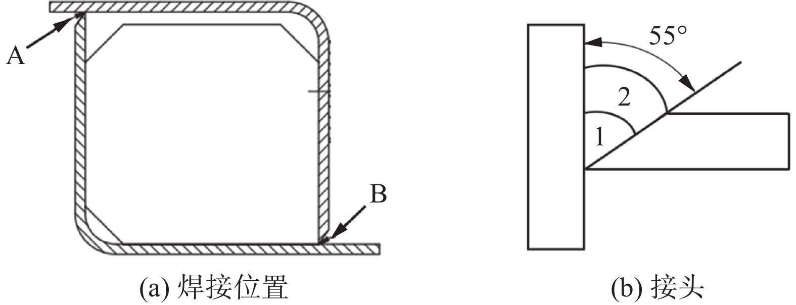
弦梁焊接结构模型如图1所示,长度13 832 mm,截面长和宽均在100 mm左右,钢板厚度为4 mm,由2块经过折弯成形的弯板焊接连接而成,工件材料为Q460E 低合金高强钢,填充金属为CHW-55C1,化学成分见表1和表2,弦梁共有2条焊缝,坡口均为55°的HY形坡口,焊缝位置和接头如图2所示. 试验采用熔化极活性气体保护焊焊接,工艺参数见表3,采用2种不同的焊接顺序,以图2中焊缝标识为基准,A侧焊缝打底焊道和盖面焊道依次设为A1,A2;B侧焊缝同样设为B1,B2,焊接顺序①依次按照A1,A2,B1,B2进行焊接,焊接顺序②依次按照B1,B2,A1,A2进行焊接.
表 1 Q460E钢化学成分(质量分数,%)Table 1. Chemical composition of Q460E steelC Mn Si P S V Nb Al Fe 0.15 1 0.35 0.009 0.008 0.003 0.015 0.053 余量 表 2 CHW-55C1的化学成分(质量分数,%)Table 2. Chemical composition of CHW-55C1C Si Mn Mo P S Cr Ni Fe 0.084 0.53 1.06 0.12 0.010 0.010 0.070 0.93 余量 ![]() 图 2 焊缝位置和接头示意图Figure 2. Schematic of weld position and welded joint. (a) weld position; (b) welded joint表 3 焊接工艺参数Table 3. Welding parameters
图 2 焊缝位置和接头示意图Figure 2. Schematic of weld position and welded joint. (a) weld position; (b) welded joint表 3 焊接工艺参数Table 3. Welding parameters焊道 气体流量
Q/(L·min−1)焊接电流
I/A电弧电压
U/V焊接速度
v/(mm·s−1)线能量
q/(J·mm−1)打底 20 240 26 21.7 288 盖面 20 287 28 11.3 709 1.2 变形测量
焊接变形测量示意图如图3所示,通过细线将弦梁两端变形位移最大的位置点连接为直线,d1为图中标注的测量点与直线之间的最大距离,采用直尺测量该测量点所在的x-y截面下测量点与细线的最短距离。
2. 有限元模型
为了精确计算弦梁的焊接变形,建立了与实际结构尺寸完全相同的三维有限元网格模型,相比于传统的Godlak双椭球[14],针对于大型长直结构所开发的增强移动热源,对于网格沿焊接方向的尺寸并不敏感,即采用较大的长度尺寸网格模型对计算结果影响不大,因此,为了控制网格数量,网格单元轴向采用较大的长度尺寸,而截面方向(x-y截面)采用较小的长度尺寸,焊缝附近的网格划分的较为密集,其它区域划分的较为稀疏,有限元网格模型如图4所示,整个模型的节点数为278 092,单元数为214 294.
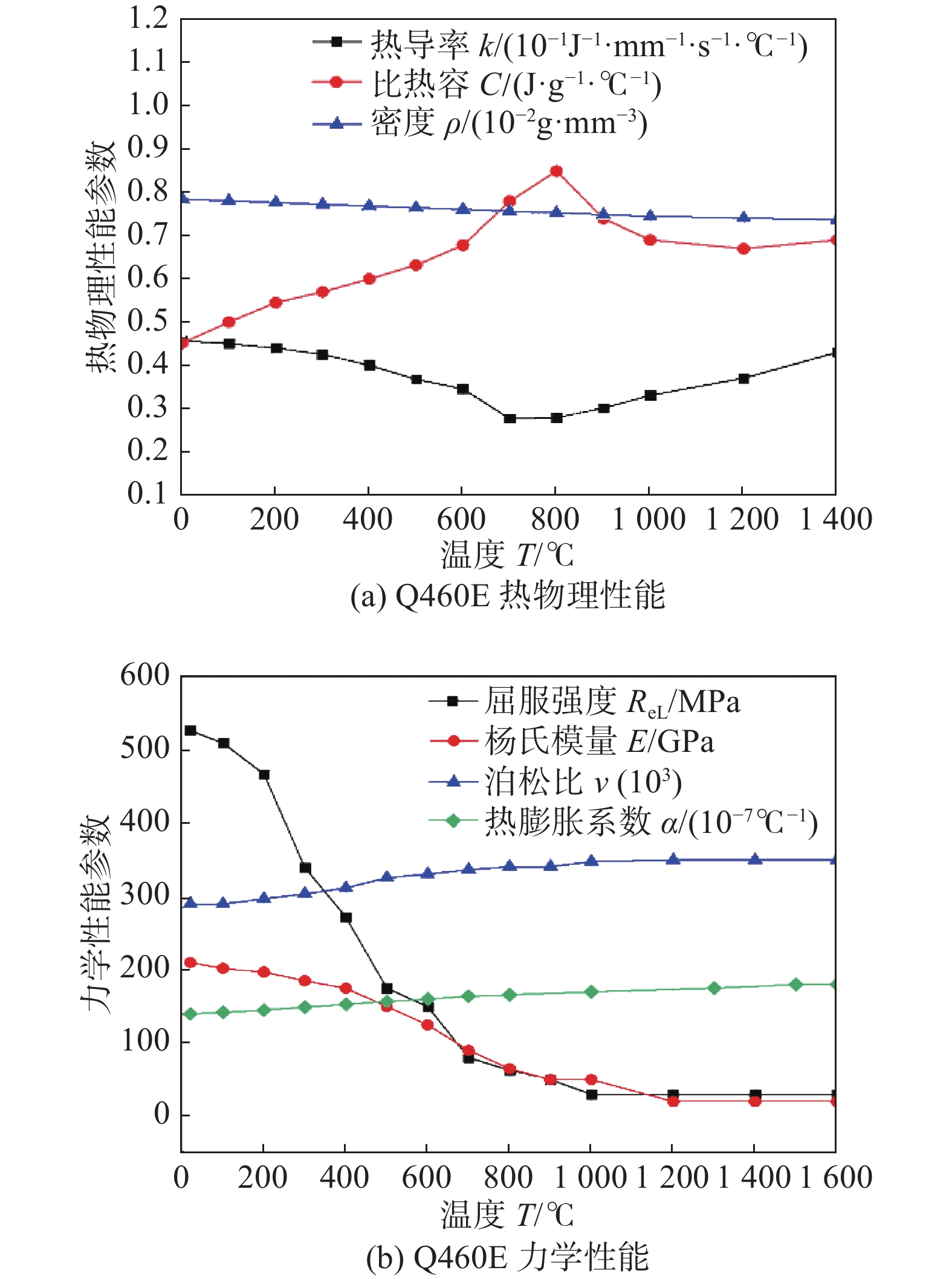
开发的有限元方法采用顺序耦合,首先进行温度场计算,再将其结果加载至位移场计算中,由于材料的热物理性能和力学参数会随着温度发生变化,计算过程考虑了温度的影响. 因为CHW-55C1焊丝与母材Q460E的各项参数差别不大,且焊缝在整体结构中占比较小,所以计算中假定焊缝区域的材料属性与母材相同,Q460E的温度性能参数如图5所示[15].
![]() 图 5 Q460E钢的温度性能参数Figure 5. Temperature-dependent properties of Q460E steel. (a) thermophysical properties of Q460E; (b) mechanical properties of Q460E
图 5 Q460E钢的温度性能参数Figure 5. Temperature-dependent properties of Q460E steel. (a) thermophysical properties of Q460E; (b) mechanical properties of Q460E2.1 热源模型和温度场计算
在可变长度热源与瞬间热源的基础上,开发出增强移动热源来模拟焊接过程的热输入. 增强移动热源是根据弦梁三维网格模型尺寸建立的长条型等密度热源,其形状尺寸与网格单元尺寸相匹配,网格单元的轴向长度约为30 ~ 50 mm,为了使热源加载时能够形成稳定连续的温度场,热源长度尺寸设为200 mm,约为传统双椭球热源的10倍,截面尺寸与焊缝截面尺寸相当,如图6所示. 相较于传统Godlak双椭球热源,增强移动热源能够大幅度提升计算效率,且对网格模型的宽容度有很大提升,此外,与瞬间热源相比,采用“增强移动热源”进行计算能够较大程度还原弦梁结构焊接过程中的拘束状态,提高焊接变形的预测精度.
焊接模拟过程中,通过调整焊接速度和热输入,保证计算时焊接总热输入与试验总热输入量保持一致,试验的焊接热输入为
$$ Q{\text{ = }}UI\eta $$ (1) 式中:U为电弧电压;I为焊接电流;η为热效率.
为保证模拟过程中焊接热输入和加热时间与实际焊接过程相同,定义了增强移动热源的2个重要参数:qv为热源的热流密度;
$v'$ 为等效焊接速度,计算过程中热流密度和等效焊接速度为$$ \begin{gathered} \left\{ {\begin{array}{*{20}{l}} {{q_v}{\text{ = }}\dfrac{{UI\eta }}{{vS}}{\text{ = }}\dfrac{Q}{{vS}}}& \\ {v'{\text{ = }}\dfrac{{l v}}{{l_r^{}}}}&{} \end{array}} \right. \\ \end{gathered} $$ (2) 式中:S为热源模型截面积;
$l$ 为热源模型长度;v为焊接速度;lr为实际熔池长度.在温度场计算中,内部的热传导采用非线性传热方程描述,焊接过程中,采用Newton冷却方程考虑热量的散失[16],同时通过Stefan-Boltzmann辐射定律考虑电弧的热辐射,温度场模拟时单元类型为全积分六面体传热单元.
2.2 位移场计算
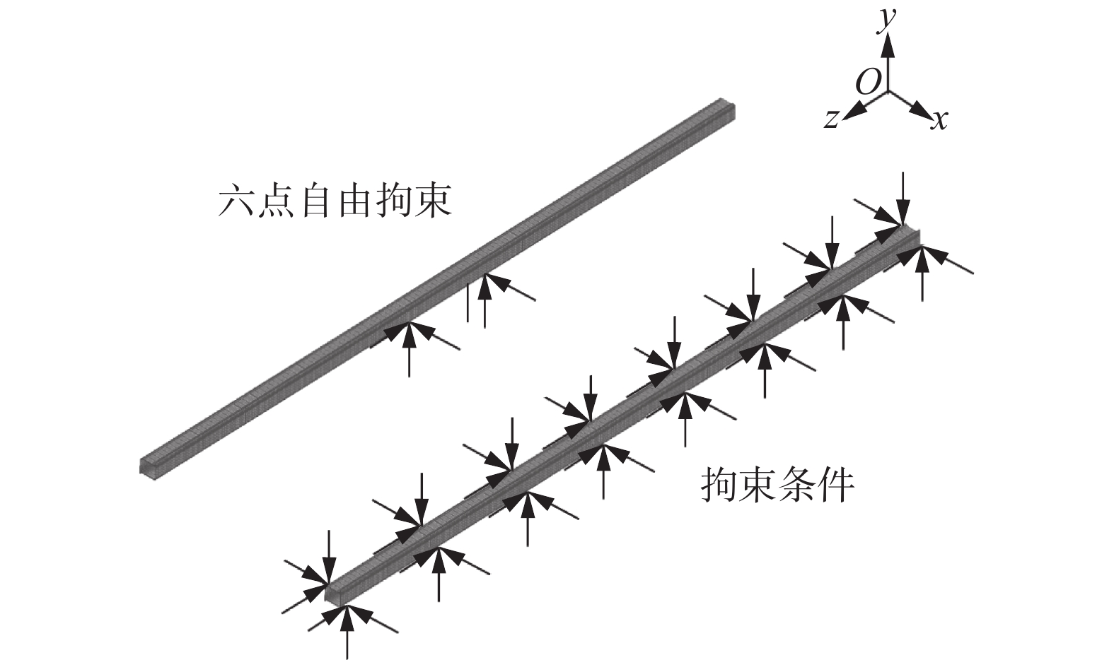
将温度场计算模型的单元类型改为全积分六面体结构单元用于焊接变形计算,为防止结构产生刚性位移,添加如图7所示六点自由拘束,同时,根据实际焊接条件,在弦梁轴向方向每间隔1 mm位置添加节点拘束,由于低碳钢焊接变形受到固态相变的影响较小[17],因此计算中不考虑固态相变的影响,另外,高温停留时间较短,计算中也可不考虑蠕变的影响. 材料的弹性行为通过各向同性Hook定律考虑,通过热膨胀系数对热应变进行计算,材料发生的塑性变形采用Von-Mises屈服准则进行计算. 低碳钢加工硬化性能远低于不锈钢[18],Q460E钢不考虑加工硬化,采用理想弹塑性模型. 弦梁在焊接过程中产生较大的变形,结构刚性随着工艺过程发生了改变,采用大变形理论考虑几何非线性,大变形理论中用来描述应变与位移的关系为[19]
$$ {\varepsilon _x} = \frac{{\partial u}}{{\partial x}} + \frac{1}{2}\left\{ {{{\left(\frac{{\partial u}}{{\partial x}}\right)}^2} + {{\left(\frac{{\partial v}}{{\partial x}}\right)}^2} + {{\left(\frac{{\partial w}}{{\partial x}}\right)}^2}} \right\} $$ (3) $$ {\varepsilon _y} = \frac{{\partial v}}{{\partial y}} + \frac{1}{2}\left\{ {{{\left(\frac{{\partial u}}{{\partial y}}\right)}^2} + {{\left(\frac{{\partial v}}{{\partial y}}\right)}^2} + {{\left(\frac{{\partial w}}{{\partial y}}\right)}^2}} \right\} $$ (4) $$ {\varepsilon _{\textit{z}}} = \frac{{\partial w}}{{\partial {\textit{z}}}} + \frac{1}{2}\left\{ {{{\left(\frac{{\partial u}}{{\partial {\textit{z}}}}\right)}^2} + {{\left(\frac{{\partial v}}{{\partial {\textit{z}}}}\right)}^2} + {{\left(\frac{{\partial w}}{{\partial {\textit{z}}}}\right)}^2}} \right\} $$ (5) $$ {\gamma _{xy}}= \frac{{\partial u}}{{\partial y}} + \frac{{\partial v}}{{\partial x}} + \left\{ {\left(\frac{{\partial u}}{{\partial x}}\right)\left(\frac{{\partial u}}{{\partial y}}\right) + \left(\frac{{\partial v}}{{\partial x}}\right)\left(\frac{{\partial v}}{{\partial y}}\right) + \left(\frac{{\partial w}}{{\partial x}}\right)\left(\frac{{\partial w}}{{\partial y}}\right)} \right\} $$ (6) $$ {\gamma _{y{\textit{z}}}} = \frac{{\partial v}}{{\partial {\textit{z}}}} + \frac{{\partial w}}{{\partial y}} + \left\{ {\left(\frac{{\partial u}}{{\partial y}}\right)\left(\frac{{\partial u}}{{\partial {\textit{z}}}}\right) + \left(\frac{{\partial v}}{{\partial y}}\right)\left(\frac{{\partial v}}{{\partial {\textit{z}}}}\right) + \left(\frac{{\partial w}}{{\partial y}}\right)\left(\frac{{\partial w}}{{\partial {\textit{z}}}}\right)} \right\} $$ (7) $${\gamma _{x{\textit{z}}}} = \frac{{\partial u}}{{\partial {\textit{z}}}} + \frac{{\partial w}}{{\partial x}} + \left\{ {\left(\frac{{\partial u}}{{\partial x}}\right)\left(\frac{{\partial u}}{{\partial {\textit{z}}}}\right) + \left(\frac{{\partial v}}{{\partial x}}\right)\left(\frac{{\partial v}}{{\partial {\textit{z}}}}\right) + \left(\frac{{\partial w}}{{\partial x}}\right)\left(\frac{{\partial w}}{{\partial {\textit{z}}}}\right)} \right\} $$ (8) 式中:
$ {\varepsilon _x} $ ,$ {\varepsilon _y} $ ,$ {\varepsilon _{\textit{z}}} $ 分别为x,y和z方向的正应变;$ {\gamma _{xy}} $ ,$ {\gamma _{y{\textit{z}}}} $ 和$ {\gamma _{x{\textit{z}}}} $ 分别为x-y,y-z和z-x平面上的剪切应变;u,ν,w分别为x,y,z方向的位移.2.3 计算案例
通过数值模拟的方式预测弦梁结构的焊接变形,根据焊接顺序的不同设计了2个计算案例,Case 1用焊接顺序①,Case 2用焊接顺序②. 通过计算结果与试验结果的对比,来验证计算方法的有效性,并讨论焊接顺序对弦梁结构焊接变形的影响.
3. 结果与讨论
3.1 温度场计算结果
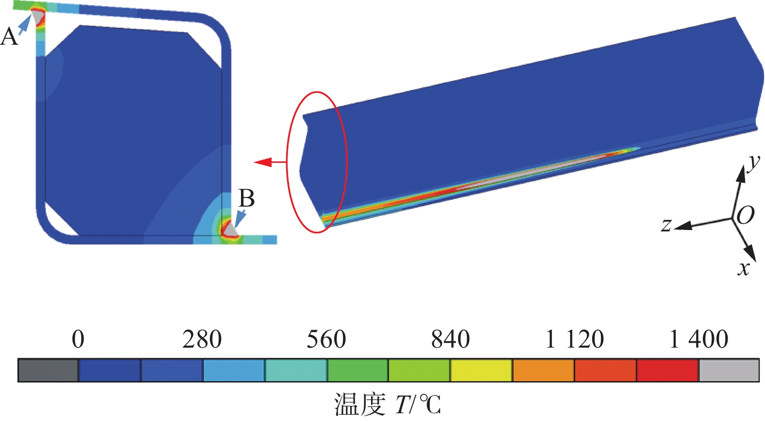
由于2个计算案例采用相同的热输入,且两侧焊道的焊接过程相对独立,因此得到的温度场计算结果相似,在这里仅列出Case 1的温度场计算结果如图8所示,图中A,B箭头指向焊缝中心表示温度高于1 400 ℃的熔化区域. 由于增强移动热源轴向尺寸的影响,图8左侧中熔池形状呈现出长、细的特点. 焊接完成后,提取弦梁截面的峰值温度分布如图8右侧所示,熔化区的范围与图4中定义的焊缝形状相似,这表明采用增强移动热源模型来计算弦梁焊接过程的温度场是基本合理的.
3.2 焊接变形计算结果
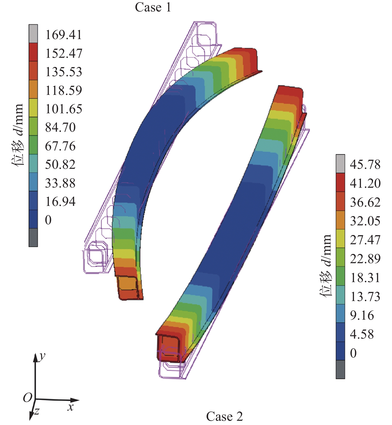
计算案例的合成位移分布如图9所示,在Case 1中,弦梁呈现出轴向方向的挠度变形,以弦梁中心为基点,1/2全长存在169.41 mm的挠度变形. 相较于Case 1,Case 2的变形大小远低于Case 1, 最大焊接变形为45.78 mm,仅为Case 1 的27%,图中Case 1和Case 2在变形模态上存在较大的差异,尽管案例中较大变形的部位均在弦梁两端,但弦梁的弯曲方向完全不同. 通过比较Case 1 和Case 2 的合成位移,可以发现焊接顺序对于弦梁结构的焊接变形存在显著影响.
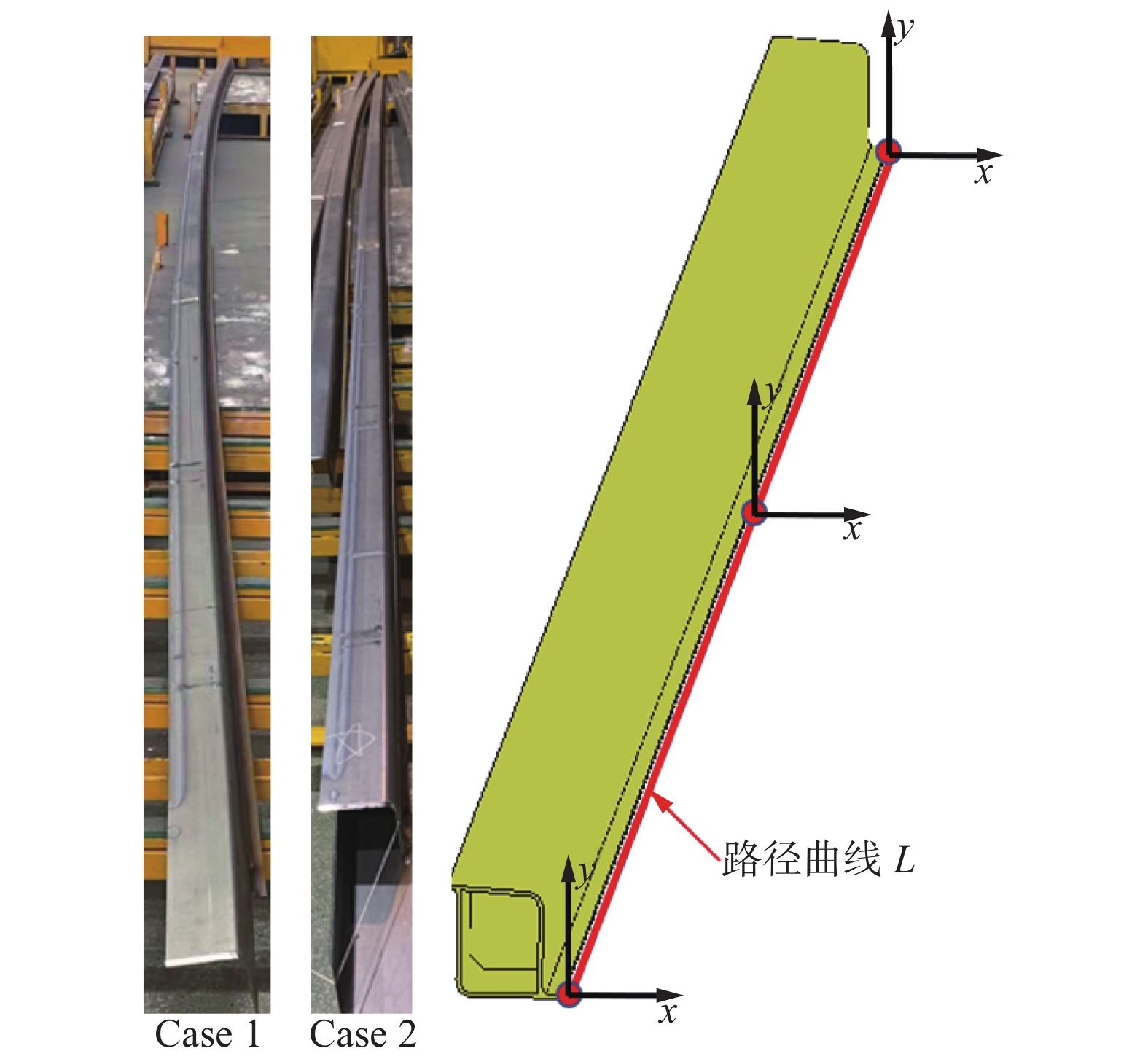
弦梁焊接变形如图10所示,采用Case 2焊接顺序下得到的弦梁焊接变形相较于Case 1案例大幅降低,这个结果与计算结果相似,此外,试验中弦梁的变形模态基本与计算结果一致. 为了评判有限元方法的有效性,方便定量分析焊接顺序对弦梁焊后变形的影响,定义了路径曲线L(图10). 从有限元计算结果中提取合成位移和x,y方向的位移沿路径曲线L的分布如图11所示,由于轴向(z方向)的位移相对较小,这里不对轴向位移做详细讨论. 试验中采用Case 1焊接顺序进行焊接的弦梁焊后变形达到了160 mm,在另一顺序下进行焊接的弦梁焊后变形达到了30 mm,在采用Case 1案例中的焊接顺序时,模拟结果和试验均表明弦梁焊后会产生较大的焊接变形,而采用Case 2焊接顺序时,二者均得到了较小的焊接变形,可以看出模拟结果能够与试验较好吻合,合成位移分布说明所开发的增强移动热源模型和有限元分析方法,针对长直弦梁结构焊接过程数值模拟有效.
![]() 图 10 弦梁焊接变形和路径曲线Figure 10. Straight beam structure welding deformation and schematic diagram of path curve
图 10 弦梁焊接变形和路径曲线Figure 10. Straight beam structure welding deformation and schematic diagram of path curve![]() 图 11 合成位移、x和y方向位移沿路径L分布Figure 11. Distribution of resultant displacement, x & y direction displacement along path L. (a) resultant displacement; (b) y direction displacement; (c) x direction displacement
图 11 合成位移、x和y方向位移沿路径L分布Figure 11. Distribution of resultant displacement, x & y direction displacement along path L. (a) resultant displacement; (b) y direction displacement; (c) x direction displacement从y方向位移分布图看,不同焊接顺序下,弦梁在焊接过程后产生了大小不同且方向完全相反的y向变形. 在Case 1中,以弦梁中部为基点,弦梁两端产生最大−y向变形98.71 mm;Case 2下, 两端均产生了最大 + y向变形43.32 mm . 与y向位移分布图一样,Case1模拟结果中x方向位移分布完全不同于Case 2,Case 1中弦梁两端产生了最大 + x方向变形约130 mm,而Case 2 中弦梁两端产生了−x向变形约20 mm. 可以看出,弦梁x,y方向的变形方向与后焊焊道相关,Case 1的后焊焊道为B侧焊道( + x侧),B焊道冷却时相对于结构中性面形成的弯矩导致弦梁在释放拘束后朝+ x,−y方向弯曲;与Case 1不同,Case 2的后焊焊道为A侧焊道(−x侧),该焊道冷却过程中相对中性面形成的弯矩驱使弦梁朝−x, + y方向弯曲. 此外,2种不同顺序下,焊接x,y方向变形的大小存在较大差距,这是因为A,B两侧焊道不对称分布于结构中性面的两侧,当A焊道和B焊道的热输入一致时,由于两侧焊道与中性面的力臂不同而产生了大小不同的弯矩,并导致了不同顺序下弦梁产生了不一样的焊接变形. 因此,对于薄壁箱型长梁结构而言,焊接顺序直接影响了结构焊后变形的模态和大小,两侧焊缝热输入保持一致的条件下,采用先焊B焊道后焊A焊道的焊接顺序能够得到较小的焊接变形.
4. 结论
(1) 采用开发的增强移动热源模型的热-弹-塑性有限元方法计算得到的弦梁结构焊接变形与试验结果吻合良好,验证了所开发的热源模型及有限元方法的有效性.
(2) 焊接顺序对大型长直结构的焊接变形的模态和大小有显著影响,等热输入的条件下,采用先焊B焊道后焊A焊道的焊接顺序能够得到较小的焊接变形. 在实际生产中,可以采用先焊接B焊道后焊接A焊道的焊接顺序控制变形.
-
![]()
图 2 焊缝位置和接头示意图
Figure 2. Schematic of weld position and welded joint. (a) weld position; (b) welded joint
![]()
图 5 Q460E钢的温度性能参数
Figure 5. Temperature-dependent properties of Q460E steel. (a) thermophysical properties of Q460E; (b) mechanical properties of Q460E
![]()
图 10 弦梁焊接变形和路径曲线
Figure 10. Straight beam structure welding deformation and schematic diagram of path curve
![]()
图 11 合成位移、x和y方向位移沿路径L分布
Figure 11. Distribution of resultant displacement, x & y direction displacement along path L. (a) resultant displacement; (b) y direction displacement; (c) x direction displacement
表 1 Q460E钢化学成分(质量分数,%)
Table 1 Chemical composition of Q460E steel
C Mn Si P S V Nb Al Fe 0.15 1 0.35 0.009 0.008 0.003 0.015 0.053 余量  下载: 导出CSV
表 2 CHW-55C1的化学成分(质量分数,%)
Table 2 Chemical composition of CHW-55C1
C Si Mn Mo P S Cr Ni Fe 0.084 0.53 1.06 0.12 0.010 0.010 0.070 0.93 余量
下载: 导出CSV
表 3 焊接工艺参数
Table 3 Welding parameters
焊道 气体流量
Q/(L·min−1)焊接电流
I/A电弧电压
U/V焊接速度
v/(mm·s−1)线能量
q/(J·mm−1)打底 20 240 26 21.7 288 盖面 20 287 28 11.3 709
下载: 导出CSV
-
[1] Liang W, Dean D. Investigating influence of external restraint on welding distortion in LAHS steel thin-plate structures by means of integrated computational approach[J]. Journal of Materials Research and Technology, 2022, 20: 2960 − 2976. doi: 10.1016/j.jmrt.2022.08.048
[2] Li Y, Li Y, Zhang C, et al. Effect of structural restraint caused by the stiffener on welding residual stress and deformation in thick-plate T-joints[J]. Journal of Materials Research and Technology, 2022, 21: 3397 − 3411. doi: 10.1016/j.jmrt.2022.10.127
[3] 芦凤桂, 邓德安, 王亚琦, 等. 数值模拟技术在激光焊接过程中的应用及发展[J]. 焊接学报, 2022, 43(8): 87 − 94. doi: 10.12073/j.hjxb.20220430001 Lu Fenggui, Deng Dean, Wang Yaqi, et al. Application and development of numerical simulation technology in laser welding process[J]. Transactions of the China Welding Institution, 2022, 43(8): 87 − 94. doi: 10.12073/j.hjxb.20220430001
[4] Zhu Z, Han Y, Zhang Z, et al. Numerical simulation of residual stress and deformation for submerged arc welding of Q690D high strength low alloy steel thick plate[J]. China Welding, 2021, 30(3): 49 − 58.
[5] Deng D, Murakawa H, Liang W. Numerical simulation of welding distortion in large structures[J]. Computer Methods in Applied Mechanics and Engineering, 2007, 196(45-48): 4613 − 4627. doi: 10.1016/j.cma.2007.05.023
[6] Liang X, Chen Q, Cheng L, et al. Modified inherent strain method for efficient prediction of residual deformation in direct metal laser sintered components[J]. Computational Mechanics, 2019, 64(6): 1719 − 1733. doi: 10.1007/s00466-019-01748-6
[7] Qian C, Xuan L, Devlin H, et al. An inherent strain based multiscale modeling framework for simulating part-scale residual deformation for direct metal laser sintering[J]. Additive Manufacturing, 2019, 28: 406 − 418. doi: 10.1016/j.addma.2019.05.021
[8] Deng D, Zhang C, Pu X, et al. Influence of material model on prediction accuracy of welding residual stress in an austenitic stainless steel multi-pass butt-welded joint[J]. Journal of Materials Engineering & Performance, 2017, 26(4): 1494 − 1505.
[9] Deng D, Kiyoshima S. Influence of annealing temperature on calculation accuracy of welding residual stress in a SUS304 stainless steel joint[J]. Acta Metallurgica Sinica, 2014, 50(5): 626 − 632.
[10] Ren S, Li S, Wang Y, et al. Finite element analysis of residual stress in 2.25Cr-1Mo steel pipe during welding and heat treatment process[J]. Journal of Manufacturing Processes, 2019, 47: 110 − 118. doi: 10.1016/j.jmapro.2019.09.019
[11] 邓德安, 清岛祥一. 用可变长度热源模拟奥氏体不锈钢多层焊对接接头的焊接残余应力[J]. 金属学报, 2010, 46(2): 195 − 200. Deng Dean, Kiyoshima S. Numerical simulation of welding residual stresses in a multi-pass butt-welded joint of austenitic stainless steel using variable length heat source[J]. Acta Metallurgica Sinica, 2010, 46(2): 195 − 200.
[12] Pu X, Zhang C, Li S, et al. Simulating welding residual stress and deformation in a multi-pass butt-welded joint considering balance between computing time and prediction accuracy[J]. The International Journal of Advanced Manufacturing Technology, 2017, 93(5): 2215 − 2226.
[13] 胡兴, 戴培元, 张超华, 等. 合并焊道法对SUS304不锈钢平板对接接头焊接残余应力计算精度和效率的影响[J]. 机械工程学报, 2019, 55(12): 72 − 82. doi: 10.3901/JME.2019.12.072 Hu Xing, Dai Peiyuan, Zhang Chaohua, et al. Influence of lumped-pass method on calculation accuracy and efficiency of welding residual stress in SUS304 stainless steel butt joints[J]. Journal of Mechanical Engineering, 2019, 55(12): 72 − 82. doi: 10.3901/JME.2019.12.072
[14] John G, Aditya C, Malcolm B. A new finite element model for welding heat sources[J]. Metallurgical Transactions B, 1984, 15(2): 299 − 305. doi: 10.1007/BF02667333
[15] 魏雷, 魏淳. Q460钢T型接头单边开坡口非对称焊接的数值模拟[J]. 热加工工艺, 2019, 7: 244 − 246. doi: 10.14158/j.cnki.1001-3814.2019.07.063 Wei Lei, Wei Chun. Numerical simulation of asymmetrical welding of Q460 steel T-joints with single side groove[J]. Hot Working Technology, 2019, 7: 244 − 246. doi: 10.14158/j.cnki.1001-3814.2019.07.063
[16] Deng D, Murakawa H. Prediction of welding distortion and residual stress in a thin plate butt-welded joint[J]. Computational Materials Science, 2008, 43(2): 353 − 365.
[17] Deng D. FEM prediction of welding residual stress and distortion in carbon steel considering phase transformation effects[J]. Materials & Design, 2009, 30(2): 359 − 366.
[18] 李索, 陈维奇, 胡龙, 等. 加工硬化和退火软化效应对 316 不锈钢厚壁管-管对接接头残余应力计算精度的影响[J]. 金属学报, 2021, 57(12): 1653 − 1666. Li Suo, Chen Weiqi, Hu Long, et al. Influence of strain hardening and annealing effect on the prediction of welding residual stresses in a thick-wall 316 stainless steel butt-welded pipe joint[J]. Acta Metallurgica Sinica, 2021, 57(12): 1653 − 1666.
[19] Wei L, Deng D. Influences of heat input, welding sequence and external restraint on twisting distortion in an asymmetrical curved stiffened panel[J]. Advances in Engineering Software, 2018, 115: 439 − 451. doi: 10.1016/j.advengsoft.2017.11.002
-
期刊类型引用(3)
1. 王磊,杜劭峰,李红星,刘港,张磊,彭勇. 钛合金蒙皮-骨架结构激光焊接变形规律模拟研究. 兵工学报. 2025(03): 266-275 .  百度学术
百度学术
2. 李长聪,赵蓓芳,李晓鹏. 天线反射面焊接过程及变形控制. 焊接技术. 2025(03): 123-126 . 百度学术
3. 任成龙. 焊接顺序和焊接方向优化在管线钢焊接中的应用. 焊接技术. 2024(09): 85-88+146 . 百度学术
其他类型引用(1)


计量
- 文章访问数: 232
- HTML全文浏览量: 70
- PDF下载量: 79
- 被引次数: 4
