
Vacuum brazing TC4 titanium alloy / 316L stainless steel with Ti43.76Zr12.50Cu37.49-xNi6.25Cox amorphous filler metals
-
摘要:
根据双团簇模型设计并制备了Ti-Zr-Cu-Ni-Co系非晶钎料,用于真空钎焊TC4钛合金和316L不锈钢,分析了钎料中Co元素含量对钎焊接头界面微观组织形貌、力学性能及断裂行为的影响规律.结果表明,钎焊接头可划分为TC4/扩散区(I区)/钎缝中心区(II区)/界面区(III区)/316L,界面典型微观组织结构为TC4/β-Ti + Ti2Cu/(Ti, Zr)2(Cu, Ni) + Ti2Cu + Ti2(Cu, Ni) + TiFe/(Fe, Cr)2Ti + α-(Fe, Cr) + τ + γ-(Fe, Ni) + σ/316L,随着Co元素含量的增加,接头剪切强度先升高后降低再升高,当Co元素含量为1.56%时达到最大310 MPa,不添加Co元素时,接头断裂于钎缝中心区(II区);当Co元素含量为1.56% ~ 6.24%时,接头断裂于靠近316L母材的界面区(III区)附近,断裂模式为典型的解理断裂.
-
关键词:
- 真空钎焊 /
- 非晶钎料 /
- 钛合金/不锈钢异种金属 /
- 微观组织 /
- 剪切强度
Abstract:Ti-Zr-Cu-Ni-Co amorphous filler metals were designed and prepared for vacuum brazing of TC4 titanium alloy to 316L stainless steel according to the dual-cluster model. The effect of Co content in filler metals on the microstructure, mechanical properties and fracture behavior of brazed joints was investigated. The results showed that the cross section of brazed joint could be divided into TC4/diffusion zone I/brazing seam center zone II/interface zone III/316L. The typical interfacial microstructure of the brazed joints was TC4/β-Ti + Ti2Cu/(Ti, Zr)2(Cu, Ni) + Ti2Cu + Ti2(Cu, Ni) + TiFe/(Fe, Cr)2Ti + α-(Fe, Cr) + τ + γ -(Fe, Ni) + σ/316L. The shear strength of brazed joints first increased, then decreased and then increased with the increase of Co content. The maximum shear strength of 310 MPa was obtained at 1.56% Co. When Co element was not added, brazed joints fractured in the center of the brazing seam (zone II). And when the Co content was 1.56 ~ 6.24%, brazed joints fractured near the interface zone (zone III) of 316L base metal. The fracture mode was typical cleavage fracture.
-
0. 序言
钛合金具有热强度高、耐蚀性好、比强度高、韧性好、密度低等优良性能,被广泛应用在航空航天、舰船和医疗等领域[1].不锈钢作为应用广泛的结构材料,具有优良的耐腐蚀性、焊接性、成形性、热稳定性和力学性能且生产成本低[2].若将钛合金和不锈钢异种金属进行连接,可使两种材料的优势相结合,二者在性能和价格实现优势互补[3],因此,开展钛/钢异种金属的连接不仅可以降低成本,还可以获得具有优异综合性能的构件,应用前景广阔,然而,钛/钢异种金属由于物理和化学性能差异显著,尤其是线膨胀系数差异较大,使得接头残余应力较大,易导致焊缝开裂;其次,Ti,Fe的互容性极差,极易产生Ti-Fe脆性金属间化合物,并且钛和钢在高温下易氧化,且钛合金高温时易吸氢元素、氧元素、氮元素,导致焊接区污染脆化,从而降低接头强度[4-5],为实现钛合金与不锈钢高质量连接,必须采用合适的焊接方法和工艺,以降低接头残余应力并减少脆性金属间化合物的生成.
目前,用于钛/钢异种金属连接的焊接方法有熔焊(电弧焊[6-7]、电子束焊[8-9]、激光焊[10-11])、固相焊(扩散焊[12-13]、摩擦焊[14-15]、爆炸焊[16-17])和钎焊[18-19],相较于其他焊接方法,真空钎焊可以显著降低接头残余应力,并抑制部分脆性相的生成,接头形式多样且真空环境可以起到净化接头的作用. Xia等人[20]采用Ti-Zr-Cu-Ni-V非晶钎料钎焊TC4钛合金与316L不锈钢,钎焊接头形成了4个不同的反应区,且接头剪切强度随钎焊温度和时间的增加先增大后减小,在960 ℃/25 min时,接头剪切强度最大为70 MPa,另外,接头裂纹萌生于[Ti(Cu, Ni)2 + TiFe]/TiFe2界面,然后沿着TiFe2和α-(Fe, Cr) + τ层扩展,断裂模式为解理断裂和晶间断裂;朱瑞等人[21]采用Ti-Zr-Hf-Cu-Ni高熵非晶钎料真空钎焊TC4钛合金和316L不锈钢,发现接头分为316L/扩散层I/焊缝中心区域II/扩散层III/TC4 5部分,在960 ℃/10 min时获得最大剪切强度205 MPa,接头断裂于靠近316L一侧的扩散层I(Fe-Ti等脆硬相).现有针对钛/钢异种金属钎焊的研究表明,钎料中组元与母材元素发生化学冶金反应,易生成Fe-Ti脆硬相而削弱接头性能,且钎料的熔点较高,使得钎焊温度也过高,从而损害母材性能,因此,钎料的成分成为钛/钢异种金属钎焊的关键.
文中设计并制备了Ti43.76Zr12.50Cu37.49-xNi6.25Cox(x = 0,1.56,3.12,4.68,6.24)系非晶钎料,用于真空钎焊TC4钛合金和316L不锈钢,通过添加合金元素Co以降低钎料熔点,改善钎料性能,从而提高接头强度,重点分析了钎料中Co元素含量对钎焊接头微观组织形貌、力学性能及断裂行为的影响.
1. 试验方法
1.1 母材
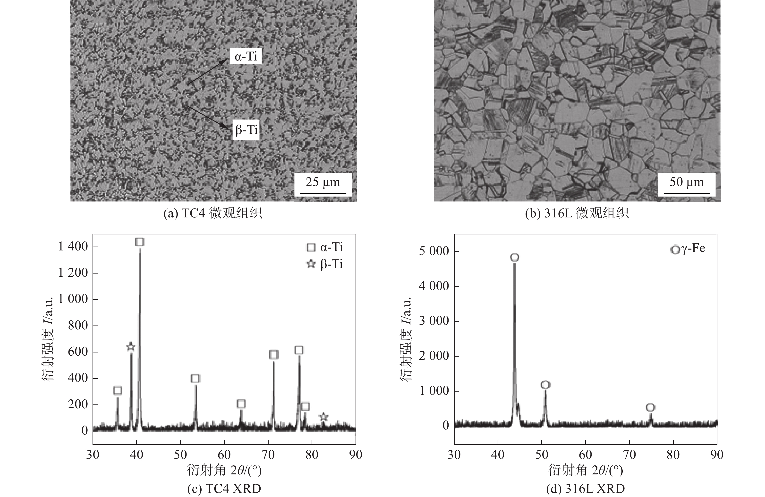
试验所用材料为TC4钛合金(TC4)和316L不锈钢(316L),采用线切割方式加工成5 mm × 5 mm × 5 mm和15 mm × 10 mm × 5 mm的小块试样,母材化学成分见表1,微观组织及XRD图谱如图1所示,可看出TC4钛合金由块状α-Ti相和围绕在α-Ti相晶界处的β-Ti相组成;316L不锈钢则由块状γ-Fe相组成.
表 1 母材化学成分(质量分数,%)Table 1. Chemical compositions of base metals母材 Al V Cr Ni Mo Mn Fe Ti TC4 5.9 3.6 — — — — — 余量 316L — — 16.5 10.2 2.0 1.3 余量 — ![]() 图 1 母材的微观组织和XRD图谱Figure 1. Microstructure and XRD patterns of base metals. (a) TC4 microstructure; (b) 316L microstructure; (c) TC4 XRD; (d) 316L XRD
图 1 母材的微观组织和XRD图谱Figure 1. Microstructure and XRD patterns of base metals. (a) TC4 microstructure; (b) 316L microstructure; (c) TC4 XRD; (d) 316L XRD1.2 钎料
根据双团簇加连接原子模型[22]设计Ti-Cu基非晶钎料,解析其共晶点,从而对非晶合金进行成分设计和优化,以获得更大非晶成形能力的钎料.采用相似元素(Zr,Ni,Co)替换方法对二元共晶点成分进行优化,通过元素之间的原子特性(原子半径和电负性接近)和混合焓(ΔH绝对值接近于0)判断两元素是否为相似元素,ΔHTi-Zr = 0 kJ/mol、ΔHCu-Ni = 4 kJ/mol、ΔHCu-Co = 6 kJ/mol[23],故可将Zr元素视为类Ti元素, Ni元素和Co元素视为类Cu元素,制备了不同Co元素含量的Ti-Zr-Cu-Ni-Co系非晶钎料.
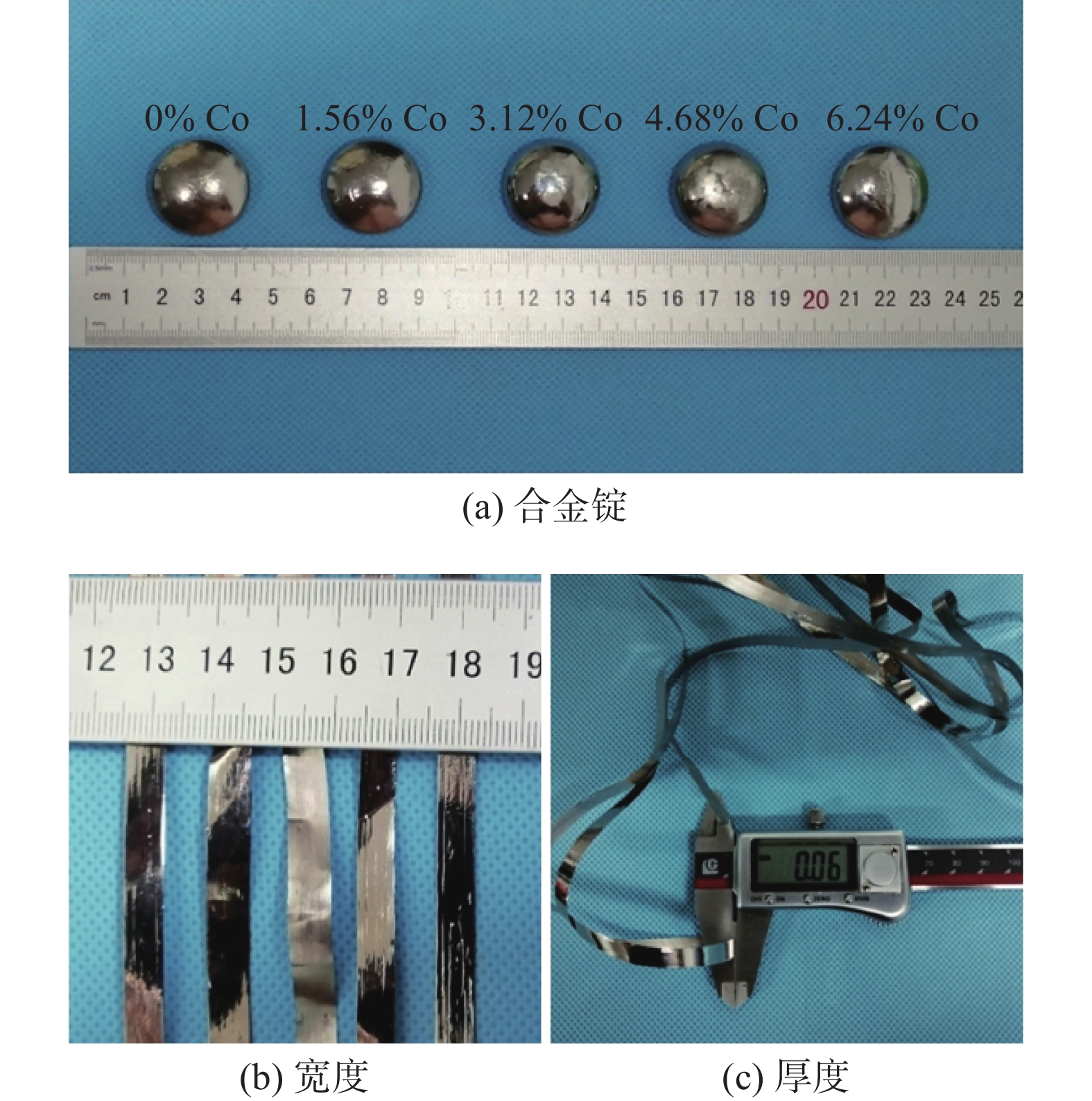
采用真空电弧熔炼甩带一体设备(DHL-350)制备Ti-Zr-Cu-Ni-Co系非晶钎料,原料(Ti,Zr,Cu,Ni和Co,纯度为99.99%)按设计好的成分比例进行混合,放置于真空电弧熔炼炉内熔炼为成分均匀的合金锭,并将合金锭剪碎用酒精超声清洗5 min,通过液态急冷甩带设备制备出宽度约6 mm,厚度约60 μm的非晶钎料箔带,如图2所示.
![]() 图 2 Ti-Zr-Cu-Ni-Co系非晶钎料Figure 2. Ti-Zr-Cu-Ni-Co Ingots amorphous filler metals. (a) ingots; (b) width; (c) thickness
图 2 Ti-Zr-Cu-Ni-Co系非晶钎料Figure 2. Ti-Zr-Cu-Ni-Co Ingots amorphous filler metals. (a) ingots; (b) width; (c) thickness1.3 钎焊工艺
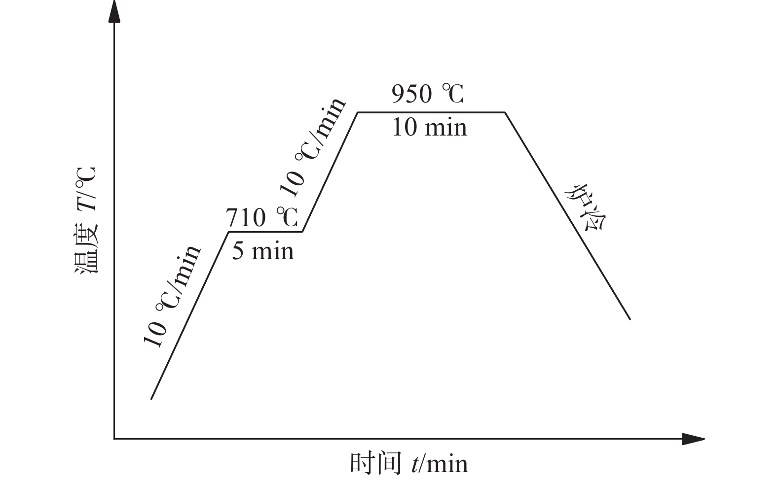
钎焊试验前,TC4和316L母材用80号,400号和800号水磨性砂纸逐级打磨,去除待焊试样表面的氧化膜,并使用无水乙醇超声清洗15 min.如图3所示,按照TC4/钎料箔带/316L“三明治”的结构装配试样,放置于真空钎焊炉(ZTF2-10)中,施加20 kPa的外在压力使得试样间紧密贴合,待钎焊炉内真空度达到6 × 10⁻³ Pa时,开始升温加热,钎焊温度设定为950 ℃,保温时间为10 min,具体的钎焊工艺加热曲线如图4所示.
![]() 图 3 钎焊装配和剪切夹具示意图Figure 3. Schematic diagram of brazing assembly and shear test fixture. (a) brazing assembly; (b) shear test fixture
图 3 钎焊装配和剪切夹具示意图Figure 3. Schematic diagram of brazing assembly and shear test fixture. (a) brazing assembly; (b) shear test fixture1.4 表征方法
采用D8 Advance型布鲁克X射线衍射仪(X-ray diffraction,XRD)对钎料晶体结构进行表征,并采用TGA/DSC3 + 型热分析仪(differential thermal analyzer,DTA)对其固液相线温度进行测试,采用JXA-8530F PLUS型场发射电子探针(electron probe micro-analyzer,EPMA)对钎焊接头界面微观组织、相分布和断裂路径进行表征和分析. 采用图3(b)所示的自制专用压剪夹具在DNS 100型万能试验机上测量接头剪切强度,剪切速率为0.5 mm/min,采用配备能谱仪(energy dispersive spectrometer,EDS)的Zeiss SUPRA55型场发射扫描电镜(scanning electron microscope,SEM)观察接头断口形貌.
2. 试验结果与分析
2.1 钎料的晶体结构与差热分析
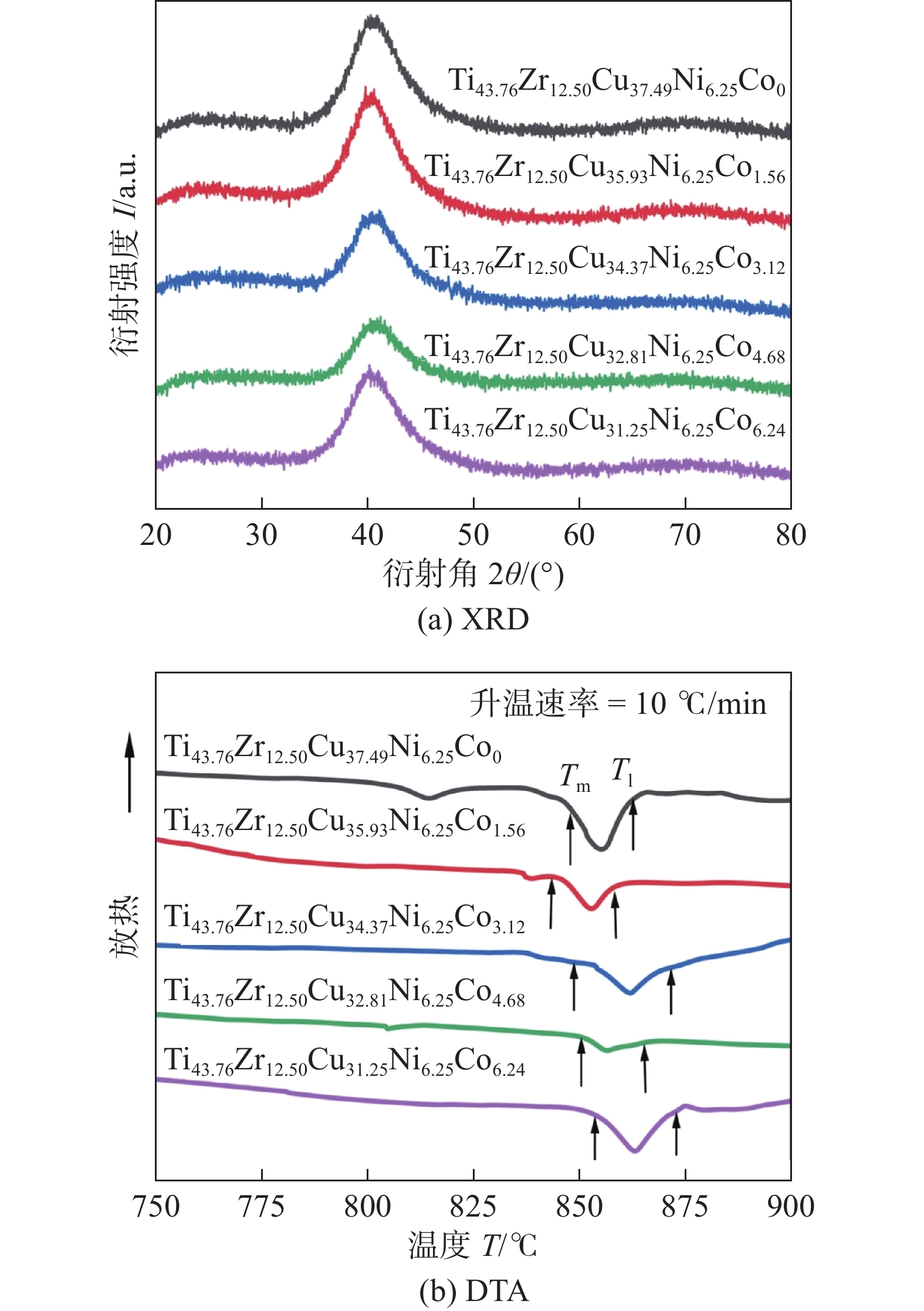
Ti-Zr-Cu-Ni-Co系非晶体钎料表征,如图5所示,Ti-Zr-Cu-Ni-Co系钎料箔带的XRD 如图5(a)所示,可知所有图谱在 2θ为38° ~ 45°时均出现一个宽大的漫衍射峰,说明这5种钎料箔带均为非晶结构.图5(b)为钎料箔带的DTA 曲线,其升温速率为10 ℃ /min,可以看出DTA曲线在800 ~ 900 ℃之间有一个明显的吸热峰.表2为钎料的固液相线温度,可看出Co元素的加入改变了钎料的熔化温度区间,当Co元素含量为1.56%时,钎料的液相线温度(Tl)和熔化温度区间(Tl ~ Tm)均达到最小,表明该钎料具有较好的流动性.钎焊温度需高于钎料液相线温度30 ~ 80 ℃以保证钎料的润湿性和流动性,因此,文中钎焊温度设定为950 ℃.
![]() 图 5 Ti-Zr-Cu-Ni-Co系非晶钎料表征Figure 5. Ti-Zr-Cu-Ni-Co amorphous filler metals. (a) XRD patterns; (b) DTA curves表 2 钎料的固相线温度(Tm)和液相线温度(Tl)Table 2. Solidus temperature and liquidus temperature of filler metals
图 5 Ti-Zr-Cu-Ni-Co系非晶钎料表征Figure 5. Ti-Zr-Cu-Ni-Co amorphous filler metals. (a) XRD patterns; (b) DTA curves表 2 钎料的固相线温度(Tm)和液相线温度(Tl)Table 2. Solidus temperature and liquidus temperature of filler metals钎料 固相线
温度
Tm/℃液相线
温度
Tl/℃熔化温度
区间
Tl ~ Tm/℃Ti43.76Zr12.50Cu37.49Ni6.25Co0 847 862 15 Ti43.76Zr12.50Cu35.93Ni6.25Co1.56 843 855 12 Ti43.76Zr12.50Cu34.37Ni6.25Co3.12 849 872 23 Ti43.76Zr12.50Cu32.81Ni6.25Co4.68 850 864 14 Ti43.76Zr12.50Cu31.25Ni6.25Co6.24 854 873 19 2.2 钎焊接头的界面典型微观组织
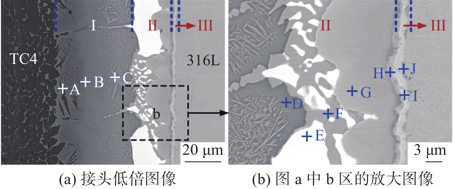
图6为950 ℃/10 min钎焊条件下使用Ti43.76Zr12.50Cu35.93Ni6.25Co1.56钎料钎焊接头的界面典型微观组织,表3为图6中标记位置的化学成分定量分析结果.从图6(a)可以看出接头形成了3个不同的区域(I、II和III区),分别为靠近TC4母材的扩散区I区,钎缝中心区II区和靠近316L母材的界面区III区. I区是TC4母材和钎料相互扩散而形成的一个扩散区,由靠近TC4母材侧的针状组织和灰色组织组成,针状组织是典型的魏氏体组织,位置A处的物相成分为85.6% Ti + 11.3% Al, Al元素为α-Ti稳定元素,因此位置A为α-Ti相;位置B的主要成分是75.8% Ti,此外还包含4.6% 的β-Ti稳定元素 Cu,其在钎焊过程中降低了α-Ti向β-Ti转变的温度,促进β-Ti的形成,因此推断该处物相为β-Ti;位置D具有相同的物相;C位置的主要元素为Ti和Cu,Ti与Cu元素含量的比值为2∶1,由Ti-Cu二元相图[24]推测该位置为Ti2Cu相.
![]() 图 6 Ti43.76Zr12.50Cu35.93Ni6.25Co1.56钎料钎焊接头的微观组织Figure 6. Microstructure of brazed joint with Ti43.76Zr12.50Cu35.93Ni6.25Co1.56 filler metal. (a) low-magnification image of the joint and (b) magnified image of zone b in a表 3 图6中标记位置的EPMA点元素分析结果(原子分数,%)Table 3. EPMA analysis results of the marked locations in Fig. 6
图 6 Ti43.76Zr12.50Cu35.93Ni6.25Co1.56钎料钎焊接头的微观组织Figure 6. Microstructure of brazed joint with Ti43.76Zr12.50Cu35.93Ni6.25Co1.56 filler metal. (a) low-magnification image of the joint and (b) magnified image of zone b in a表 3 图6中标记位置的EPMA点元素分析结果(原子分数,%)Table 3. EPMA analysis results of the marked locations in Fig. 6点 Ti Cu Zr Ni Co Al V Fe Cr 可能相 A 85.6 0.8 0.3 0.1 — 11.3 1.6 0.2 — α-Ti B 75.8 4.6 0.6 1.4 0.3 7.2 5.8 3.9 0.6 β-Ti C 66.1 23.1 2.5 2.3 0.2 1.9 1.1 2.1 0.8 Ti2Cu D 72.6 7.0 2.8 1.4 0.3 4.5 2.7 6.2 2.5 β-Ti E 40.8 25.0 15.8 4.4 0.4 5.3 1.3 5.4 1.7 (Ti, Zr)2(Cu, Ni) F 63.0 27.9 3.7 2.6 0.2 0.8 0.4 1.3 0.2 Ti2Cu G 50.8 22.0 2.2 3.9 0.9 2.5 1.0 14.3 2.5 Ti2(Cu, Ni) + TiFe H 32.0 0.9 0.9 4.0 0.4 0.5 0.3 52.4 8.5 (Fe, Cr)2Ti I 3.9 0.6 — 3.4 0.3 0.1 0.8 59.1 31.8 α-(Fe, Cr) + τ J 1.0 0.3 — 9.3 0.5 — 0.1 70.8 18.0 γ-(Fe, Ni) + σ II区由白色物相(位置E)、网状共晶组织(位置F)和灰色物相(位置G)组成,由表3可知,位置E主要元素为40.8% Ti + 25.0% Cu + 15.8% Zr + 4.4% Ni,由Cu-Ti-Zr三元相图[25]可知,E位置的反应相为Ti2Cu和Zr2Cu的混合物. Li等人[26]指出,Cu和Ni元素以及Zr和Ti两组元素的原子特性相近,可以无限固溶,故Ni元素可以视为类Cu元素,Zr元素可以视为类Ti元素,因此,E位置的Ti2Cu + Zr2Cu进一步被认为是(Ti, Zr)2(Cu, Ni),F位置Ti和Cu元素含量比值约为2∶1(表3),因此该相为Ti2Cu相,位置G主要元素为Ti, Cu, Fe,此外含有极少量Co元素,根据Cu-Fe-Ti三元相图[27]可知,在G位置形成了Ti2Cu + TiFe相,考虑到Cu,Ni,Co之间完全混溶和Xia等人[28]的研究,可以进一步认为是Ti2(Cu, Ni) + TiFe相.
由图6(b)可以明显看出III区形成了3个反应层,第一层中H位置的相主要由32.0% Ti + 52.4% Fe + 8.5% Cr组成,由Ti-Fe-Cr三元相图[29]可推断出该位置为(Fe, Cr)2Ti相,位置I(第二层)的物相为α-(Fe, Cr) + τ(Ti5Cr7Fe17),位置J(第三层)的主要元素有Fe,Ni,Cr,根据Fe-Cr-Ni三元相图[30]可知,其物相为γ-(Fe, Ni) + σ.
采用Ti43.76Zr12.50Cu35.93Ni6.25Co1.56非晶钎料钎焊TC4/316L得到接头的元素分布结果如图7所示,可以看出I区的反应层厚度相对较宽,其主要元素为Ti,可推断为Ti基固溶体;II区由白色物相和灰色物相组成,白色相主要是由Cu,Zr,Ti,Ni元素组成,可能是由于钎焊过程中钎料扩散不充分而残留在此区域,灰色相的主要元素为Ti,Cu,Fe,Ni,对于Co元素,由于Co和Fe元素的良好相容性,它更倾向于扩散靠近到316L侧的灰色相,Zr元素在白色相中出现了大量富集的现象,这主要是由于Zr元素扩散能力较差,难以实现长距离扩散到两侧母材而残留在钎缝中所致;III区的反应层厚度较小,由316L母材侧界面微观组织面扫描结果为图8,该区主要是Ti,Fe和Cr 3种元素,从Ni和Cr的元素分布中可明显看出,该区出现了明显的贫Ni现象,且靠近316L母材侧存在Cr元素大量富集现象.
![]() 图 7 采用Ti43.76Zr12.50Cu35.93Ni6.25Co1.56非晶钎料钎焊接头的元素分布Figure 7. Elemental distribution of brazed joint with Ti43.76Zr12.50Cu35.93Ni6.25Co1.56 amorphous filler metal
图 7 采用Ti43.76Zr12.50Cu35.93Ni6.25Co1.56非晶钎料钎焊接头的元素分布Figure 7. Elemental distribution of brazed joint with Ti43.76Zr12.50Cu35.93Ni6.25Co1.56 amorphous filler metal![]() 图 8 采用Ti43.76Zr12.50Cu35.93Ni6.25Co1.56非晶钎料钎焊接头316L母材侧的元素分布Figure 8. Elemental distribution at 316L base metal side of brazed joint with Ti43.76Zr12.50Cu35.93Ni6.25Co1.56 amorphous filler metal
图 8 采用Ti43.76Zr12.50Cu35.93Ni6.25Co1.56非晶钎料钎焊接头316L母材侧的元素分布Figure 8. Elemental distribution at 316L base metal side of brazed joint with Ti43.76Zr12.50Cu35.93Ni6.25Co1.56 amorphous filler metal图9为上述钎焊接头的线扫描结果,从图9(a)可以看出,I区Ti,Fe元素含量呈现相反的变化趋势,Ti元素含量逐渐降低,TC4母材中的Ti元素含量明显不同于靠近TC4母材侧钎缝中的Ti元素含量,可见TC4母材中的Ti元素扩散到了钎料中,而Fe含量逐渐升高,说明 316L母材中的Fe元素向TC4母材侧扩散;II区主要元素为Ti,Cu,Zr,Ni和Fe,这5种元素含量变化较为复杂且均呈现出阶梯型变化,主要是因为不同物相中元素的偏聚程度不同,进而对316L母材侧接头放大的线扫描元素分布如图9(b)所示;III区中Ti和 Fe元素呈相反的变化趋势,说明在浓度梯度的作用下,Ti和Fe元素与界面发生了互扩散,并在凝固过程中生成了Ti-Fe脆性相,Cr元素在此区域发生了富集现象,这是因为钎焊过程中,钎料中的Ti元素扩散到了316L不锈钢母材中削弱了Cr元素的活性,降低了Cr元素在316L母材中的溶解度,从而导致Cr元素在界面反应层出现了偏聚.
![]() 图 9 采用Ti43.76Zr12.50Cu35.93Ni6.25Co1.56非晶钎料钎焊接头元素线扫描分布Figure 9. Elemental line scanning distribution of brazed joint with Ti43.76Zr12.50Cu35.93Ni6.25Co1.56 amorphous filler metal. (a) integral joint; (b) magnified image of zone b in 9(a)
图 9 采用Ti43.76Zr12.50Cu35.93Ni6.25Co1.56非晶钎料钎焊接头元素线扫描分布Figure 9. Elemental line scanning distribution of brazed joint with Ti43.76Zr12.50Cu35.93Ni6.25Co1.56 amorphous filler metal. (a) integral joint; (b) magnified image of zone b in 9(a)2.3 Co元素含量对接头界面微观组织的影响
不同Co元素含量非晶钎料钎焊接头界面微观组织如图10所示. 钎料与TC4钛合金和316L不锈钢母材均紧密结合,无裂纹、未焊合等常见焊接缺陷的出现,说明所设计钎料对母材具有良好的流动性,与母材形成了良好的冶金连接.钎焊接头均形成了3个不同区域,I区靠近TC4母材侧均有针状魏氏体生成,且魏氏体的数量随Co元素含量的增加而增多,这是由于Co元素的电负性比Ti强,增加钎料中Co元素的含量,可以促进钎料与TC4母材之间的相互扩散.在不同Co元素含量条件下,II区形态变化最为明显,Co元素含量为0和1.56%时,II区存在明显的网状共晶组织,当Co元素含量超过1.56%时,网状共晶组织Ti2Cu相消失,且Co元素含量为1.56%时钎料残留(白色相)较少,表明该钎料流动性好,与母材的扩散和反应更充分.III区的高倍形貌如图10(a1) ~ 图10(e1)所示,图11为钎焊接头III区Ti-Fe化合物层的厚度随钎料中Co元素含量增加而变化的趋势,钎料中Co元素的加入,使得III区Ti-Fe化合物层厚度有减小趋势,这是由于Co元素的加入抑制了部分脆性相的生成所致.
![]() 图 10 950 ℃/10 min条件下不同Co含量非晶钎料钎焊接头界面微观组织Figure 10. Effect of Co content in filler metals on interfacial microstructure of brazed joint at 950 ℃/10 min. (a) 0%; (b) 1.56%; (c) 3.12%; (d) 4.68%; (e) 6.24%
图 10 950 ℃/10 min条件下不同Co含量非晶钎料钎焊接头界面微观组织Figure 10. Effect of Co content in filler metals on interfacial microstructure of brazed joint at 950 ℃/10 min. (a) 0%; (b) 1.56%; (c) 3.12%; (d) 4.68%; (e) 6.24%![]() 图 11 不同Co元素含量钎焊接头III区Ti-Fe化合物层的厚度Figure 11. Thickness of Ti-Fe reaction layer in zone III of brazed joints with different Co content
图 11 不同Co元素含量钎焊接头III区Ti-Fe化合物层的厚度Figure 11. Thickness of Ti-Fe reaction layer in zone III of brazed joints with different Co content2.4 Co元素含量对钎焊接头力学性能的影响
950 ℃/10 min条件下不同Co元素含量非晶钎料钎焊接头剪切强度如图12所示,随着Co元素含量的增加,接头剪切强度先升高后降低再升高,当Co元素含量由0增加到1.56%时,接头强度大幅度增加,且Co元素含量为1.56%时,接头剪切强度达到最大为310 MPa. 当Co元素含量增加到3.12%时,接头强度又显著下降,进一步增加Co元素含量到6.24%时,接头强度呈现升高趋势.钎料Co元素含量的增加会改变钎料液相线温度,使得钎料流动性有所不同而影响接头性能.Co元素含量为3.12%时,钎料的液相线温度较高,流动性差,从而导致大部分钎料残留在钎缝中与母材过度反应,生成了大量的Ti-Fe脆性相而削弱了接头性能.Co元素含量为1.56%时,钎料具有较好的流动性,可与母材实现良好的冶金结合,获得高强度接头,且接头剪切强度高于文献中报道的剪切强度[31].
![]() 图 12 950 ℃/10 min条件下不同Co元素含量非晶钎料钎焊接头的剪切强度Figure 12. Shear strength of brazed joints with different Co content filler metals at 950 ℃/10 min
图 12 950 ℃/10 min条件下不同Co元素含量非晶钎料钎焊接头的剪切强度Figure 12. Shear strength of brazed joints with different Co content filler metals at 950 ℃/10 min2.5 Co元素含量对钎焊接头断裂行为的影响
图13为不同Co元素含量非晶钎料钎焊接头断裂路径.从图13右图中可看出,Co元素含量为0%,钎焊接头断裂于(Ti, Zr)2(Cu, Ni) + Ti2Cu 界面;Co元素含量为1.56% ~ 6.24%时,接头均沿TiFe层断裂;当Co元素含量为1.56%时,可从图13(b)看出有二次裂纹的产生,二次裂纹穿过TiFe层,沿着TiFe2/FeCr界面扩展.由于二次裂纹在断裂过程中需要吸收大量的断裂载荷,从而使得接头强度提高. 当Co元素含量为0%时,断裂发生在钎缝中心区(II区),主要是因为该条件下II区中钎料残留(Ti, Zr)2(Cu, Ni)相过多,加剧了钎缝中心区的脆硬性,说明未加Co元素的非晶钎料钎焊接头性能较差;当Co元素含量为1.56% ~ 6.24%时,断裂均发生于靠近316L母材的界面区(III区)附近,III区含有τ,TiFe2,TiFe等脆性相,加剧了裂纹的萌生和扩展,使得该区域成为钎焊接头的薄弱位置.
![]() 图 13 950 ℃/10 min条件下不同Co元素含量非晶钎料钎焊接头断裂路径Figure 13. Fracture path of brazed joints with different Co content filler metals at 950 ℃/10 min. (a) 0%; (b) 1.56%; (c) 3.12%; (d) 4.68%; (e) 6.24%
图 13 950 ℃/10 min条件下不同Co元素含量非晶钎料钎焊接头断裂路径Figure 13. Fracture path of brazed joints with different Co content filler metals at 950 ℃/10 min. (a) 0%; (b) 1.56%; (c) 3.12%; (d) 4.68%; (e) 6.24%钎焊接头断口形貌如图14所示,表4为对应位置的EDS分析结果.母材两侧断口上均存在大量解理台阶和解理面,从图14(a)中 TC4侧断口可以观察到河流花样(位置A)及316L断口侧层状分布的扇形解理花样(位置E),呈典型的解理断裂模式.根据表4,断口检测到了FeCr,TiFe和TiFe2等物相.如图15所示,钎焊接头断口的XRD图谱也说明了母材两侧断口存在Ti-Fe,Fe-Cr等物相,与前文断裂路径、断口形貌物相的分析结果一致,最终可判断添加Co元素钎料的钎焊接头断裂位置位于III区附近.
![]() 图 14 使用不同钎料钎焊接头断口形貌Figure 14. Fracture morphology of brazed joints. (a) Ti43.76Zr12.50Cu35.93Ni6.25Co1.56; (b) Ti43.76Zr12.50Cu34.37Ni6.25Co3.12表 4 图14中标记位置的EDS点元素分析结果(原子分数,%)Table 4. EDS analysis results of the marked locations in Fig. 14
图 14 使用不同钎料钎焊接头断口形貌Figure 14. Fracture morphology of brazed joints. (a) Ti43.76Zr12.50Cu35.93Ni6.25Co1.56; (b) Ti43.76Zr12.50Cu34.37Ni6.25Co3.12表 4 图14中标记位置的EDS点元素分析结果(原子分数,%)Table 4. EDS analysis results of the marked locations in Fig. 14点 Ti Cu Zr Ni Co Al V Fe Cr 可能相 A 48.4 25.4 5.7 4.8 1.3 2.7 0.7 9.8 1.3 Ti2Cu B 53.8 25.2 11.0 2.8 0.2 3.2 0.4 2.9 0.6 (Ti, Zr)2(Cu, Ni) C 48.1 24.7 13.9 3.8 0.4 3.4 0.7 3.9 1.2 (Ti, Zr)2(Cu, Ni) D 30.8 0.7 2.1 3.4 0.6 1.1 0.4 50.5 10.5 TiFe2 E 48.5 21.7 3.2 3.8 1.3 3.7 0.7 14.9 2.4 Ti2(Cu, Ni) + TiFe F 48.3 23.6 3.5 5.2 1.2 2.3 — 13.9 2.0 Ti2(Cu, Ni) + TiFe G 58.1 12.1 10.2 3.4 0.8 6.5 1.9 5.6 1.6 (Ti, Zr)2(Cu, Ni) H 49.1 18.9 2.0 7.1 2.6 2.6 0.5 15.3 1.9 Ti2(Cu, Ni) + TiFe I 49.9 19.1 2.7 5.7 2.6 3.5 0.6 14.2 1.7 Ti-Cu-Fe J 11.5 0.4 0.7 2.9 0.3 0.7 0.6 57.0 26.0 FeCr K 38.2 5.6 1.3 5.4 1.5 1.6 0.3 36.9 9.3 TiFe L 47.9 19.4 3.0 6.0 2.4 2.9 0.3 16.0 2.2 Ti-Cu-Fe ![]() 图 15 使用不同钎料钎焊接头断口XRD图谱Figure 15. XRD patterns of fracture surfaces. (a) Ti43.76Zr12.50Cu35.93Ni6.25Co1.56; (b) Ti43.76Zr12.50Cu34.37Ni6.25Co3.12
图 15 使用不同钎料钎焊接头断口XRD图谱Figure 15. XRD patterns of fracture surfaces. (a) Ti43.76Zr12.50Cu35.93Ni6.25Co1.56; (b) Ti43.76Zr12.50Cu34.37Ni6.25Co3.123. 结论
(1)钎料中Co元素的加入显著降低了钎焊接头Ti-Fe反应层厚度,随着Co元素含量的增加,接头剪切强度先升高后降低再升高,当Co元素含量为1.56%时,接头剪切强度达到最大310 MPa.
(2)钎焊接头可分为3个典型区域,分别为靠近TC4母材的扩散区(I区)、钎缝中心区(II区)和靠近316L母材的界面区(III区). 接头界面典型微观组织结构为TC4/β-Ti + Ti2Cu/(Ti, Zr)2(Cu, Ni) + Ti2Cu + Ti2(Cu, Ni) + TiFe/(Fe, Cr)2Ti + α-(Fe, Cr) + τ + γ-(Fe, Ni) + σ/316L.
(3)TC4钛合金母材与Ti-Zr-Cu-Ni-Co系非晶态钎料有良好的化学相容性.接头断裂均发生在靠近316L母材侧的TiFe层,断裂模式为典型的解理断裂.而未添加Co元素的接头断裂于钎缝中心区(II区),性能较差,界面区中生成了TiFe和TiFe2等脆性相削弱了接头的力学性能.
-
![]()
图 1 母材的微观组织和XRD图谱
Figure 1. Microstructure and XRD patterns of base metals. (a) TC4 microstructure; (b) 316L microstructure; (c) TC4 XRD; (d) 316L XRD
![]()
图 2 Ti-Zr-Cu-Ni-Co系非晶钎料
Figure 2. Ti-Zr-Cu-Ni-Co Ingots amorphous filler metals. (a) ingots; (b) width; (c) thickness
![]()
图 3 钎焊装配和剪切夹具示意图
Figure 3. Schematic diagram of brazing assembly and shear test fixture. (a) brazing assembly; (b) shear test fixture
![]()
图 5 Ti-Zr-Cu-Ni-Co系非晶钎料表征
Figure 5. Ti-Zr-Cu-Ni-Co amorphous filler metals. (a) XRD patterns; (b) DTA curves
![]()
图 6 Ti43.76Zr12.50Cu35.93Ni6.25Co1.56钎料钎焊接头的微观组织
Figure 6. Microstructure of brazed joint with Ti43.76Zr12.50Cu35.93Ni6.25Co1.56 filler metal. (a) low-magnification image of the joint and (b) magnified image of zone b in a
![]()
图 7 采用Ti43.76Zr12.50Cu35.93Ni6.25Co1.56非晶钎料钎焊接头的元素分布
Figure 7. Elemental distribution of brazed joint with Ti43.76Zr12.50Cu35.93Ni6.25Co1.56 amorphous filler metal
![]()
图 8 采用Ti43.76Zr12.50Cu35.93Ni6.25Co1.56非晶钎料钎焊接头316L母材侧的元素分布
Figure 8. Elemental distribution at 316L base metal side of brazed joint with Ti43.76Zr12.50Cu35.93Ni6.25Co1.56 amorphous filler metal
![]()
图 9 采用Ti43.76Zr12.50Cu35.93Ni6.25Co1.56非晶钎料钎焊接头元素线扫描分布
Figure 9. Elemental line scanning distribution of brazed joint with Ti43.76Zr12.50Cu35.93Ni6.25Co1.56 amorphous filler metal. (a) integral joint; (b) magnified image of zone b in 9(a)
![]()
图 10 950 ℃/10 min条件下不同Co含量非晶钎料钎焊接头界面微观组织
Figure 10. Effect of Co content in filler metals on interfacial microstructure of brazed joint at 950 ℃/10 min. (a) 0%; (b) 1.56%; (c) 3.12%; (d) 4.68%; (e) 6.24%
![]()
图 11 不同Co元素含量钎焊接头III区Ti-Fe化合物层的厚度
Figure 11. Thickness of Ti-Fe reaction layer in zone III of brazed joints with different Co content
![]()
图 12 950 ℃/10 min条件下不同Co元素含量非晶钎料钎焊接头的剪切强度
Figure 12. Shear strength of brazed joints with different Co content filler metals at 950 ℃/10 min
![]()
图 13 950 ℃/10 min条件下不同Co元素含量非晶钎料钎焊接头断裂路径
Figure 13. Fracture path of brazed joints with different Co content filler metals at 950 ℃/10 min. (a) 0%; (b) 1.56%; (c) 3.12%; (d) 4.68%; (e) 6.24%
![]()
图 14 使用不同钎料钎焊接头断口形貌
Figure 14. Fracture morphology of brazed joints. (a) Ti43.76Zr12.50Cu35.93Ni6.25Co1.56; (b) Ti43.76Zr12.50Cu34.37Ni6.25Co3.12
![]()
图 15 使用不同钎料钎焊接头断口XRD图谱
Figure 15. XRD patterns of fracture surfaces. (a) Ti43.76Zr12.50Cu35.93Ni6.25Co1.56; (b) Ti43.76Zr12.50Cu34.37Ni6.25Co3.12
表 1 母材化学成分(质量分数,%)
Table 1 Chemical compositions of base metals
母材 Al V Cr Ni Mo Mn Fe Ti TC4 5.9 3.6 — — — — — 余量 316L — — 16.5 10.2 2.0 1.3 余量 —  下载: 导出CSV
表 2 钎料的固相线温度(Tm)和液相线温度(Tl)
Table 2 Solidus temperature and liquidus temperature of filler metals
钎料 固相线
温度
Tm/℃液相线
温度
Tl/℃熔化温度
区间
Tl ~ Tm/℃Ti43.76Zr12.50Cu37.49Ni6.25Co0 847 862 15 Ti43.76Zr12.50Cu35.93Ni6.25Co1.56 843 855 12 Ti43.76Zr12.50Cu34.37Ni6.25Co3.12 849 872 23 Ti43.76Zr12.50Cu32.81Ni6.25Co4.68 850 864 14 Ti43.76Zr12.50Cu31.25Ni6.25Co6.24 854 873 19
下载: 导出CSV
表 3 图6中标记位置的EPMA点元素分析结果(原子分数,%)
Table 3 EPMA analysis results of the marked locations in Fig. 6
点 Ti Cu Zr Ni Co Al V Fe Cr 可能相 A 85.6 0.8 0.3 0.1 — 11.3 1.6 0.2 — α-Ti B 75.8 4.6 0.6 1.4 0.3 7.2 5.8 3.9 0.6 β-Ti C 66.1 23.1 2.5 2.3 0.2 1.9 1.1 2.1 0.8 Ti2Cu D 72.6 7.0 2.8 1.4 0.3 4.5 2.7 6.2 2.5 β-Ti E 40.8 25.0 15.8 4.4 0.4 5.3 1.3 5.4 1.7 (Ti, Zr)2(Cu, Ni) F 63.0 27.9 3.7 2.6 0.2 0.8 0.4 1.3 0.2 Ti2Cu G 50.8 22.0 2.2 3.9 0.9 2.5 1.0 14.3 2.5 Ti2(Cu, Ni) + TiFe H 32.0 0.9 0.9 4.0 0.4 0.5 0.3 52.4 8.5 (Fe, Cr)2Ti I 3.9 0.6 — 3.4 0.3 0.1 0.8 59.1 31.8 α-(Fe, Cr) + τ J 1.0 0.3 — 9.3 0.5 — 0.1 70.8 18.0 γ-(Fe, Ni) + σ
下载: 导出CSV
表 4 图14中标记位置的EDS点元素分析结果(原子分数,%)
Table 4 EDS analysis results of the marked locations in Fig. 14
点 Ti Cu Zr Ni Co Al V Fe Cr 可能相 A 48.4 25.4 5.7 4.8 1.3 2.7 0.7 9.8 1.3 Ti2Cu B 53.8 25.2 11.0 2.8 0.2 3.2 0.4 2.9 0.6 (Ti, Zr)2(Cu, Ni) C 48.1 24.7 13.9 3.8 0.4 3.4 0.7 3.9 1.2 (Ti, Zr)2(Cu, Ni) D 30.8 0.7 2.1 3.4 0.6 1.1 0.4 50.5 10.5 TiFe2 E 48.5 21.7 3.2 3.8 1.3 3.7 0.7 14.9 2.4 Ti2(Cu, Ni) + TiFe F 48.3 23.6 3.5 5.2 1.2 2.3 — 13.9 2.0 Ti2(Cu, Ni) + TiFe G 58.1 12.1 10.2 3.4 0.8 6.5 1.9 5.6 1.6 (Ti, Zr)2(Cu, Ni) H 49.1 18.9 2.0 7.1 2.6 2.6 0.5 15.3 1.9 Ti2(Cu, Ni) + TiFe I 49.9 19.1 2.7 5.7 2.6 3.5 0.6 14.2 1.7 Ti-Cu-Fe J 11.5 0.4 0.7 2.9 0.3 0.7 0.6 57.0 26.0 FeCr K 38.2 5.6 1.3 5.4 1.5 1.6 0.3 36.9 9.3 TiFe L 47.9 19.4 3.0 6.0 2.4 2.9 0.3 16.0 2.2 Ti-Cu-Fe
下载: 导出CSV
-
[1] 赵永庆, 葛鹏. 我国自主研发钛合金现状与进展[J]. 航空材料学报, 2014, 34(4): 51 − 61. Zhao Yongqing, Ge Peng. Current situation and development of new titanium alloys invented in China[J]. Journal of Aeronautical Materials, 2014, 34(4): 51 − 61.
[2] 宋庭丰, 蒋小松, 莫德锋, 等. 不锈钢和钛合金异种金属焊接研究进展[J]. 材料导报, 2015, 29(6): 81 − 87. Song Tingfeng, Jiang Xiaosong, Mo Defeng, et al. A survey on dissimilar welding of stainless steel and titanium alloy[J]. Materials Reports, 2015, 29(6): 81 − 87.
[3] 李鹏, 李京龙, 熊江涛, 等. 添加Ni + Nb中间层的钛合金与不锈钢扩散焊工艺研究[J]. 航空材料学报, 2011, 31(3): 46 − 51. Li Peng, Li Jinglong, Xiong Jiangtao, et al. Study on diffusion bonded titanium alloy to stainless steel with Ni + Nb interlayers[J]. Journal of Aeronautical Materials, 2011, 31(3): 46 − 51.
[4] 邓云华, 岳喜山, 李晓辉, 等. TC4钛合金/304不锈钢异种材料蜂窝结构钎焊工艺[J]. 焊接学报, 2019, 40(10): 148 − 155. Deng Yunhua, Yue Xishan, Li Xiaohui, et al. Brazing process of TC4 titanium/304 stainless steel dissimilar materials honeycomb sandwich structure[J]. Transactions of the China Welding Institution, 2019, 40(10): 148 − 155.
[5] 王廷, 张秉刚, 陈国庆, 等. 钛/钢异种金属焊接存在问题及研究现状[J]. 焊接, 2009(9): 29 − 33. Wang Ting, Zhang Binggang, Chen Guoqing, et al. Problems and research status of welding of dissimilar metals between titanium alloy and steel[J]. Welding & Joining, 2009(9): 29 − 33.
[6] Hao X H, Dong H G, Li S, et al. Lap joining of TC4 titanium alloy to 304 stainless steel with fillet weld by GTAW using copper-based filler wire[J]. Journal of Materials Processing Tech, 2018, 257: 88 − 100. doi: 10.1016/j.jmatprotec.2018.02.020
[7] Liu H, Cheng Z, Huang J H, et al. Feasibility study of different filler metals on MIG-TIG double-sided arc brazing of titanium alloy-stainless steel[J]. Journal of Manufacturing Processes, 2019, 47: 183 − 191. doi: 10.1016/j.jmapro.2019.09.029
[8] 王廷, 张秉刚, 张艳桥, 等. 采用不同结构Cu/V填充层的钛合金/不锈钢电子束焊接试验[J]. 焊接学报, 2014, 35(8): 71 − 74. Wang Ting, Zhang Binggang, Zhang Yanqiao, et al. Experimental research on electron beam welding of titanium alloy to stainless steel based on Cu/V filler metals with different shapes[J]. Transactions of the China Welding Institution, 2014, 35(8): 71 − 74.
[9] Tomashchuk I, Sallamand P, Belvavina N, et al. Evolution of microstructures and mechanical properties during dissimilar electron beam welding of titanium alloy to stainless steel via copper interlayer[J]. Materials Science and Engineering:A, 2013, 585: 114 − 122. doi: 10.1016/j.msea.2013.07.050
[10] Zhang Y, Sun D Q, Gu X Y, et al. Nd/YAG pulsed laser welding of TC4 titanium alloy to 301L stainless steel via pure copper interlayer[J]. The International Journal of Advanced Manufacturing Technology, 2017, 90(1-4): 953 − 961. doi: 10.1007/s00170-016-9453-z
[11] Fang Y J, Jiang X S, Song T F, et al. Pulsed laser welding of Ti-6Al-4V titanium alloy to AISI 316L stainless steel using Cu/Nb bilayer[J]. Materials Letters, 2019, 244: 163 − 166. doi: 10.1016/j.matlet.2019.02.075
[12] Balasubramanian M. Development of processing windows for diffusion bonding of Ti-6Al-4V titanium alloy and 304 stainless steel with silver as intermediate layer[J]. Transactions of Nonferrous Metals Society of China, 2015, 25(9): 2932 − 2938. doi: 10.1016/S1003-6326(15)63919-X
[13] Li P, Li C, Dong H G, et al. Vacuum diffusion bonding of TC4 titanium alloy to 316L stainless steel with AlCoCrCuNi2 high-entropy alloy interlayer[J]. Journal of Alloys and Compounds, 2022, 909: 164698. doi: 10.1016/j.jallcom.2022.164698
[14] Li P, Dong H G, Xia Y Q, et al. Inhomogeneous interface structure and mechanical properties of rotary friction welded TC4 titanium alloy/316L stainless steel joints[J]. Journal of Manufacturing Processes, 2018, 33: 54 − 63. doi: 10.1016/j.jmapro.2018.05.001
[15] Liu H H, Aoki Y, Aoki Y, et al. Principle for obtaining high joint quality in dissimilar friction welding of Ti-6Al-4V alloy and SUS316L stainless steel[J]. Journal of Materials Science & Technology, 2020, 46: 211 − 224.
[16] Chu Q L, Zhang M, Li J H, et al. Experimental and numerical investigation of microstructure and mechanical behavior of titanium/steel interfaces prepared by explosive welding[J]. Materials Science and Engineering:A, 2017, 689: 323 − 331. doi: 10.1016/j.msea.2017.02.075
[17] Zhou Q, Liu R, Ran C, et al. Effect of microstructure on mechanical properties of titanium-steel explosive welding interface[J]. Materials Science and Engineering:A, 2022, 830: 142260. doi: 10.1016/j.msea.2021.142260
[18] Han K, Wang T, Chang S T, et al. Interface characteristics and mechanical property of titanium/steel joint by electron beam brazing with 72Ag-28Cu filler metal[J]. Journal of Manufacturing Processes, 2020, 59: 58 − 67. doi: 10.1016/j.jmapro.2020.09.049
[19] Xia Y Q, Dong H G, Li P, et al. Brazing TC4 titanium alloy/316L stainless steel joint with Ti50- xZr xCu39Ni11 amorphous filler metals[J]. Journal of Alloys and Compounds, 2020, 849: 156650. doi: 10.1016/j.jallcom.2020.156650
[20] Xia Y Q, Li P, Hao X H, et al. Interfacial microstructure and mechanical property of TC4 titanium alloy/316L stainless steel joint brazed with Ti-Zr-Cu-Ni-V amorphous filler metal[J]. Journal of Manufacturing Processes, 2018, 35: 382 − 395. doi: 10.1016/j.jmapro.2018.08.022
[21] 朱瑞, 李国选, 汪月勇, 等. TC4钛合金-316L不锈钢真空钎焊接头组织与性能研究[J]. 有色金属工程, 2021, 11(12): 8 − 14. doi: 10.3969/j.issn.2095-1744.2021.12.002 Zhu Rui, Li Guoxuan, Wang Yueyong, et al. An investigation on microstructure and mechanical properties of vacuum brazed TC4 titanium to 316L stainless steel[J]. Nonferrous Metals Engineering, 2021, 11(12): 8 − 14. doi: 10.3969/j.issn.2095-1744.2021.12.002
[22] Ma Y P, Dong D D, Dong C, et al. Composition formulas of binary eutectics[J]. Scientific Reports, 2015, 5: 14 − 18.
[23] Takeuchi A, Inoue A. Classification of bulk metallic glasses by atomic size difference, heat of mixing and period of constituent elements and its application to characterization of the main alloying element[J]. Materials Transactions, 2005, 46(12): 2817 − 2829. doi: 10.2320/matertrans.46.2817
[24] Akbarpour M R, Mirabad H M, Hemmati A, et al. Processing and microstructure of Ti-Cu binary alloys: A comprehensive review[J]. Progress in Materials Science, 2022: 100933.
[25] Turchanin M A, Velikanova T Y, Agraval P G, et al. Thermodynamic assessment of the Cu-Ti-Zr system. III. Cu-Ti-Zr System[J]. Powder Metallurgy and Metal Ceramics, 2007, 47: 586 − 606.
[26] Li X Q, Li L, Hu K, et al. Vacuum brazing of TiAl-based intermetallics with Ti-Zr-Cu-Ni-Co amorphous alloy as filler metal[J]. Intermetallics, 2015, 57: 7 − 16. doi: 10.1016/j.intermet.2014.09.010
[27] Raghavan V. Cu-Fe-Ti (Copper-Iron-Titanium)[J]. Journal of Phase Equilibria, 2002, 23(2): 172 − 174. doi: 10.1361/1054971023604152
[28] Xia Y Q, Dong H G, Zhang R Z, et al. Interfacial microstructure and shear strength of Ti6Al4V alloy/316 L stainless steel joint brazed with Ti33.3Zr16.7Cu50-xNix amorphous filler metals[J]. Materials & Design, 2020, 187: 108380.
[29] Zeng L J, Liu L B, Huang S X, et al. Experimental investigation of phase equilibria in the Ti-Fe-Cr ternary system[J]. Calphad, 2017, 58: 58 − 69. doi: 10.1016/j.calphad.2017.05.006
[30] Yen Y W, Su J W, Huang D P. Phase equilibria of the Fe-Cr-Ni ternary systems and interfacial reactions in Fe–Cr alloys with Ni substrate[J]. Journal of Alloys and Compounds, 2007, 457(1/2): 270 − 278.
[31] Cao X, Dong K W, Zhu R, et al. A high-strength vacuum brazed TC4/316L joint with a Ti-Zr-based amorphous ribbon as the filler metal[J]. Vacuum, 2021, 187: 110070.
-
期刊类型引用(6)
1. 董博文,史光远,钟素娟,董显,程亚芳,龙伟民,张冠星. 钎料短流程成型技术研究现状(英文). 稀有金属材料与工程. 2025(02): 377-384 .  百度学术
百度学术
2. 夏月庆,杜强,郭鹏,秦建,路全彬,丁宗业,李鹏,董红刚,纠永涛,周培林,张秀丽. 钛/钢异质金属压力焊与钎焊研究进展. 精密成形工程. 2025(03): 67-80 . 百度学术
3. 梁伊茗,赵明远,盛兰兵,沈元勋,钟素娟. 钛合金钎焊界面与熔蚀调控研究现状. 焊接. 2025(04): 66-77 . 百度学术
4. 李鹏,王景宽,秦志伟,丁志杰,马雄,姚佳,孙华为,程亚芳,常云峰,董红刚. TiZrNiCoNbSn高熵钎料钎焊Ti_2AlNb合金接头微观组织与性能. 精密成形工程. 2025(04): 217-225 . 百度学术
5. 田晓羽,张志伟,周晨,赵连清,田洋光,付伟,宋晓国. 钎焊温度对BNi-2非晶钎料钎焊1Cr18Ni9Ti不锈钢组织和性能的影响. 焊接学报. 2024(06): 61-67 . 本站查看
6. 李鹏,张振阳,张亮亮,马雄,孙兵兵,李超,董红刚. (TiZrHf)_(40)(NiCu)_(55)Al_5高熵非晶钎料真空钎焊Ti_2AlNb/GH4169合金. 焊接学报. 2024(08): 1-11 . 本站查看
其他类型引用(0)


计量
- 文章访问数: 327
- HTML全文浏览量: 113
- PDF下载量: 70
- 被引次数: 6
