Comparative study on the microstructure and mechanical properties of the laser welded joints of additive manufactured and forged TC11 titanium alloy
-
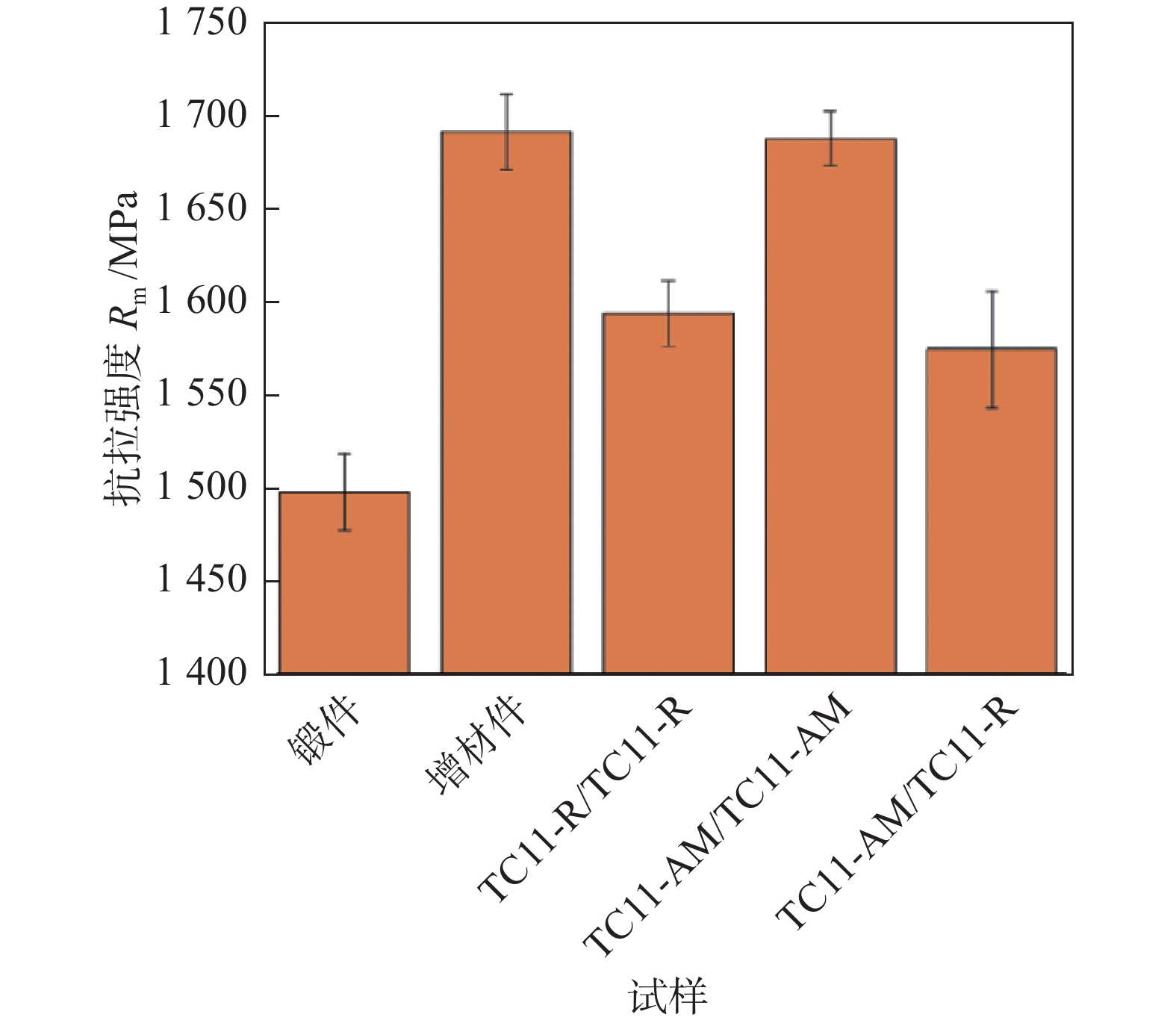
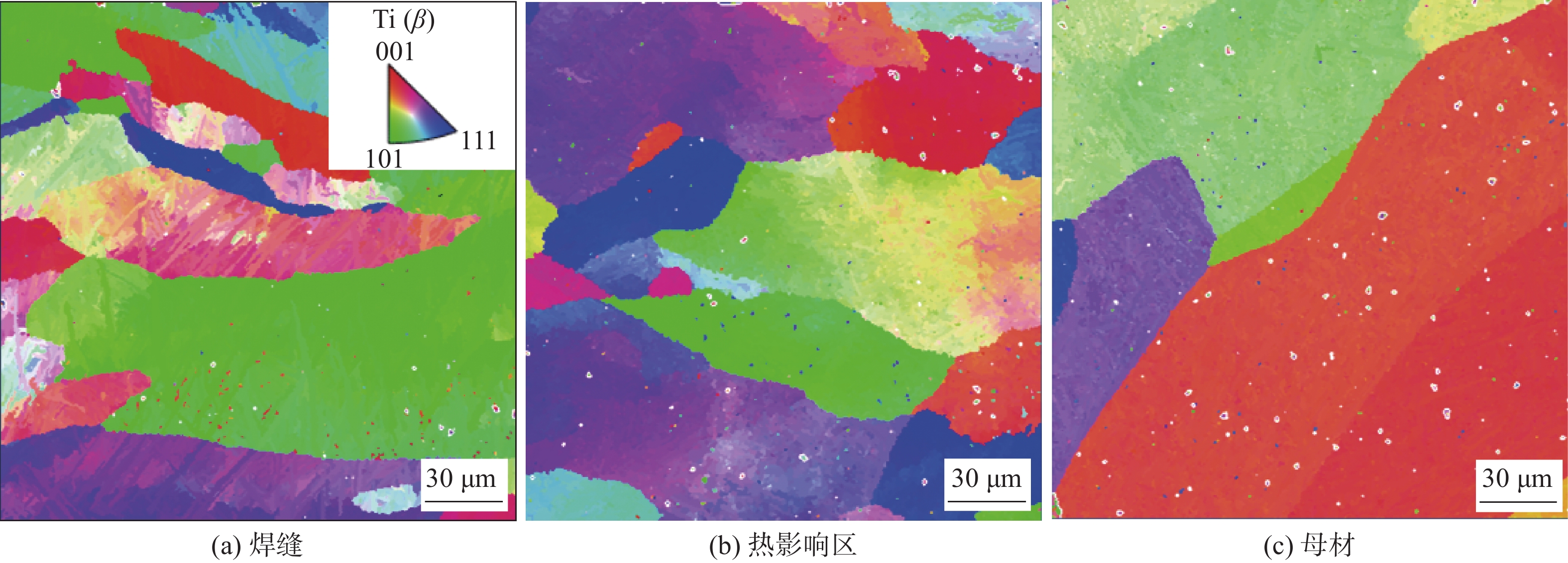
摘要: 采用增材制造方法制备航空航天大尺寸构件经常会受到加工效率、设备最大加工尺寸的限制,开发增材制造和焊接相结合的复合制造技术有望解决这一问题. 因此,开展了增材制造和锻造TC11钛合金激光焊试验,研究了增材制造TC11(TC11-AM)/锻造TC11(TC11-R),TC11-AM/TC11-AM和TC11-R/TC11-R 3种接头的焊接性,开展了焊接接头微观组织、硬度和拉伸试验,并观察了拉伸试样的断口形貌. 结果表明,3种接头的焊缝区均未发现明显的气孔缺陷. 由于熔池温度梯度大、冷却速度快,焊缝组织均为内部布满α′马氏体相的粗大柱状晶粒. 3种接头抗拉强度分别约为1 575,1 687 MPa和1 593 MPa. TC11-R/TC11-R接头和TC11-AM/TC11-AM接头横截面显微硬度呈高斯分布,硬度值分别为445 HV ± 31 HV和424 HV ± 6 HV.由于接头不同区域的组织差异明显,TC11-AM/TC11-R接头显微硬度呈台阶状分布,硬度值为432 HV ± 21 HV. 3种接头的拉伸试样均为韧性断裂,发现断裂面均有大量韧窝.通过对比接头的抗拉强度可知,TC11-AM/TC11-R接头和TC11-AM/TC11-AM接头具有良好的焊接性.
-
关键词:
- 增材制造TC11合金 /
- 锻造TC11合金 /
- 激光焊 /
- 微观组织 /
- 力学性能
Abstract: Additive manufacturing of large-size components for aerospace applications is always limited by processing efficiency and the maximum machining dimension of the equipment. Therefore, it is expected that a hybrid manufacturing technology combining additive manufacturing and welding will tackle this problem. In this paper, laser welding tests of additive and forged TC11 titanium alloy were carried out. The weldability of additive TC11 titanium alloy (TC11-AM), of "TC11-AM/forged TC11 (TC11-R)" joint and of TC11-R/TC11-R joint were studied.The microstructure of welded joints, hardness and tensile tests were conducted, and the fracture morphologies of tensile specimens were observed. The results show that no obvious porosity was found in the weld zone of TC11-R/TC11-R joint, TC11-AM/TC11-R joint, or TC11-AM/TC11-AM joint. Due to the large temperature gradient and fast cooling rate of the molten pool, the microstructure of the weld was coarse columnar grain with α' martensite phase inside. The tensile strengths of the three joints mentioned above were about 1575, 1687 MPa and 1593 MPa, respectively. The cross sectional microhardness of TC11-R/TC11-R and TC11-AM/TC11-AM joints shows Gaussian distribution, and the variation range ΔHV of hardness values was about 445 HV ± 31 HV and 424 HV ± 6 HV, respectively. Due to the notable difference in the microstructures at different zones of the joint, the microhardness of TC11-AM/TC11-R joint showed a ladder-shaped distribution with higher hardness in TC11-AM side and lower hardness in TC11-R side, and the range of hardness was about 432 HV ± 21 HV. By comparing the tensile strength of the joints, it is found that TC11-AM/TC11-R joint and TC11-AM/TC11-AM joint are better in terms of weldability. -
0. 序言
以材料设计与模拟为理论基石的材料基因工程,在新材料研发过程中占有及其重要的地位. 材料基因工程中的高通量方法,在短时间内高效完成大批量样品制备与表征,包括高通量制备、高通量计算、高通量表征、高通量数据库与数据传输,其核心是将传统材料研究中的顺序迭代方法改为并行处理,以量变引起材料研究效率的质变[1-2].
作为“材料基因组技术”三大要素之一,高通量方法在材料成分设计、组织分析、性能优化、过程模拟等方面起着关键性作用[1]. 需要与“材料计算模拟”和“材料信息学/数据库”有机融合、协同发展、互相补充,方可充分发挥其加速材料研发与应用的效能,最终使材料科学走向“按需设计”的终极目标[3-5]. 钎焊是现代制造业中材料连接的重要方法之一,借助材料基因组理念[6],高通量方法是否在钎焊性能数值模拟[7]、钎料高效可控制备、钎缝微观组织分析、钎焊材料物性数据库建立等方面起到举足轻重的关键作用,值得思考与探索.
钎焊技术作为三大焊接技术的重要分支之一,是在狭窄半封闭空间内瞬间实现熔化、润湿、铺展、填充、溶解、扩散、凝固和界面反应过程[6],使得钎焊过程异常复杂、影响因素多、随机性强,国内外学者对钎焊界面状态变化、冶金反应及钎缝缺欠形成机理的研究仅限于个例,尚未形成涵盖全部因素的表征模型,在很大程度上凭经验判定,难以确保接头的使用可靠性[6, 8-9]. 利用材料基因工程中的高通量方法[10],也许可解决上述难题,故有必要开展钎焊基因工程及高通量制备的深入研究.
目前有关钎焊与高通量方法组合研究的报道较为零散,缺乏综述性报道给以详细梳理,因此文中全面阐述有关高通量方法在钎焊领域的应用研究,对于未来实现钎焊基因工程、智能钎焊工厂提供理论依据和参考信息.
1. 高通量方法在钎焊领域的应用概述
高通量方法在钎焊领域的应用以高通量制备钎料、钎料及钎焊接头的高通量计算模拟分析为主,目前国内外学者发表的学术论文20余篇(包括期刊论文、会议论文、学位论文)、公开发明专利21项,主要有哈尔滨工业大学何鹏教授、北京科技大学黄继华教授、上海交通大学陈捷狮博士、太原理工大学丁敏博士、上海大学贾延东及德国Hartz教授、乔治亚理工学院Gao Feng教授等研究组,但目前国内外有关钎焊材料与工艺方面,还未涉及高通量表征、高通量数据库与数据传输方面的研究. 上述代表性的研究成果归纳、总结如表1所示.
表 1 高通量方法在钎焊领域的代表性研究Table 1. Representative study of high-throughput methods in the field of brazing研究钎料类别 研究内容 作者 单位 文献 贵金属钎料 钎焊基因工程、智能钎焊理念提出 何鹏 哈尔滨工业大学 [6, 8] AgCuNi 定向凝固高通量制备装置、楔形轧制 谢明 贵研铂业股份有限公司 [11-12] AgCuTi 第一性原理研究钎料在SiC表面的润湿性 黄继华 北京科技大学 [13] Ag72Cu 第一性原理计算 Ag 元素在 Ti2AlC 中
元素取代倾向性和可行性王国超 哈尔滨工业大学 [14] Ag72Cu 分子动力学方法模拟钎料在铁基板的润湿特性 Hartz 德国多特蒙德大学 [15] NiCrBSi 第一性原理分析B、Si元素对金刚石钎缝
界面结合强度的影响Zhang Jian 长沙理工大学 [16] CuNiTi CuTi二元体系的电子轨道杂化 黄继华 北京科技大学 [17] AlSi梯度 梯度钎料高通量制备装置 贾延东 上海大学 [18] Al12Si、Sn基 与SiC界面的原子活性 韩雨彤 哈尔滨工业大学 [19] SnZnCu 两靶磁控溅射共沉积制备软钎料 王刚 上海大学 [20] Sn-3.5Ag 基于密度泛函理论的第一原理探索Cu6Sn5晶体结构中
掺杂剂最有利的占据位置Gao F 乔治亚理工学院 [21] SnCu 密度泛函理论的第一性原理对Cu/Cu3Sn(010)
界面Bi的偏析进行了研究Liu Z Q 中科院金属所 [22] SnZn 第一性原理计算Al2O3/Sn9Zn、Sn9Zn-1Al2O3 -xCu
钎料界面电子性能丁敏 太原理工大学 [23-24] SnCu 基于密度泛函分子动力学方法,计算母材原子在Sn轴方向的
最优迁移路径、最小能量及相应的电子结构陈捷狮 上海交通大学 [25-26] 2. 钎料高通量制备研究现状
高端装备制造对高性能材料的需求迫切,尤其是对缩短研发时间与降低成本的需求,但是新材料研发有其固有的规律和时间要求[4]. 借助高通量制备可以解决加快新材料的研发速度,降低合金的研发成本等问题. 高通量制备作为高通量试验技术的重要组成部分,是材料基因组技术能否有效进行的关键. 目前国内外有关高通量制备技术在钎焊技术领域的应用研究现状,按照软、硬钎焊技术类别,可归纳为AgCuNi钎料、AlSi梯度钎料、SnZnCu钎料的高通量制备研究,具体如下.
昆明贵金属研究所谢明课题组开发出钎料高通量定向凝固制备装置(图1),可单次完成不同成分、工艺下钎料高通量制备[11]. 在熔体温度1 150 ℃、冷却水温度及水量25 ~ 35 ℃,400 L/h,拉坯速度0.5 mm/s,氩气保护条件下,定向凝固制备直径25 mm的AgCuNi棒材,Ni含量0.5% ~ 2% (质量分数) 经系列测试,钎料性能参数如下:抗拉强度320 ~ 411 MPa,断后伸长率5.3% ~ 10.2%,固相线温度区间558 ~ 617 ℃,液相线温度区间549 ~ 586 ℃. 对AgCuNi楔形试样[12]轧制后发现:高通量样品变形量从33% ~ 80%连续变化. 该方法不足之处是拉坯过程中容易产生裂纹、夹杂等缺陷,成为制约钎料性能提升的瓶颈.
一种封装用高硅铝合金结构梯度材料高通量制备装置及方法[18],主要用于制备AlSi梯度合金钎料,钎料抗拉强度180 ~ 260 MPa,热导率139 ~ 170 W/(m·℃),热膨胀系数(12.1 ~ 17.4) × 106(25 ~ 200 ℃),制备的合金致密度更高,组织更加细化,合金具有优异的综合性能,该方法仅适用小批量制备,与工业实际规模化生产还有一定差距.
上海大学王刚课题组[20]发明了两靶共溅射沉积方法制备Sn-Zn-Cu钎料(图2),一次性可制备10种不同组分的钎料,靶材为Sn-9Zn合金和纯Cu金属,钎料成分为Cu含量20.2% ~ 20.3%,Sn含量74.38% ~ 92.77%,Zn含量4.5% ~ 7.5%. 钎料熔化温度区间:204 ~ 218.5 ℃,但制备的钎料中存在微量Cu2O和ZnO氧化物.
3. 钎焊领域高通量计算
对于材料性质的研究,理论计算与模拟具有极强的理论指导性及预见性,能够较好的解释试验结果,并对试验中的不足提出改进,进一步指导试验[3, 27-28]. 理论模拟计算研究材料性能最常用的方法主要有密度泛函理论、分子动力学、第一性原理. 将上述三种高通量计算方法应用到钎焊领域,可获得预想不到的研究结果.
3.1 硬钎焊领域
硬钎焊作为钎焊领域一个重要分支,国内外学者采用第一性原理、分子动力学等高通量计算方法对银钎料、镍钎料、铜钎料中的二元电子结构、电荷密度、原子置换等进行了系统研究,但有关钎料整体电子结构、钎焊性能方面的数值模拟、三维钎焊过程,目前还鲜有涉及,有待后续进行深入研究.
王国超[14]使用BAg-8钎料钎焊Ti2AlC和铜,利用第一性原理,从热力学角度揭示了Ag在Ti2AlC中是通过Al空位优先成片的置换,形成 Ti2(Al, Ag)C固溶体,从而保持了Ti2AlC陶瓷结构的稳定性;Ti-Ag键取代Ti-Al键,键合强度的减弱降低了体系稳定性;从原子尺度发现Ag在Ti2AlC中形成圆盘状的富Ag固溶体,证实了第一性原理计算结果. 但是有关Ti-Ag-Al之间的键合强度未涉及.
Yang等人[13]借助第一性原理计算研究Ag(111)/SiC(111)界面和Ag(111)/TiC(111)界面的界面特性,研究Ag-Cu-Ti钎料在SiC陶瓷表面的优异反应润湿性,如图3所示. 结果表明,Ag(111)/SiC(111)界面和Ag(111)/TiC(111)界面具有C端基结构和TL堆叠序列,显示出最高的界面稳定性.Ag(111)/SiC(111)界面和Ag(111)/TiC(111)界面的化学键主要通过SiC(或TiC)板中第一层C原子之间的相互作用和Ag板中的第一层Ag原子形成. Ag(111)/SiC(111)界面的界面能远大于Ag(111)/TiC(111)界面的界面能,这表明AgCuTi钎料与SiC母材之间形成TiC反应层,对提高AgCuTi钎料在SiC陶瓷上的润湿性起到积极作用. 但是有关Ti-Ag-Cu-Si之间的界面能未涉及,可能是计算软件本身的缺陷.
Hartz-Behrend等人[15]采用分子动力学模拟方法对钎焊过程固/液界面的润湿及铺展行为进行了定量分析. 分子动力学模拟能够定量反映纯铜、纯银、AgCu28钎料在铁基板上的润湿情况,与试验结果较为吻合. 但是该研究没有考虑钎料与基体之间复杂的界面传质和反应行为.
Zhang等人[16]通过第一性原理研究了Cr,B,Si对Ni-Cr-B-Si钎料钎焊金刚石界面结合强度和粘着转移的影响规律. 研究发现,Cr对镍金刚石界面具有较强的包覆能力,相对于B和Si,Cr对镍/金刚石界面具有较强的包覆能力. Cr有效地提高了界面结合强度,镍/金刚石界面的拉伸模拟试验进一步验证了Cr对镍/金刚石界面性能具有强化作用,镍/金刚石界面Cr和C原子之间强烈的离子键决定了镍基钎料钎焊金刚石界面具有高结合能. 有关Cr,B,Si对钎焊金刚石界面的耦合作用机理还有待深入研究.
Yang等人[17]采用超软赝势密度泛函的第一性原理系统研究Ag-Cu-Ti和Cu-Ni-Ti钎料中Cu-Ti体系金属间化合物的电子结构(电子轨道杂化、电子分布情况),如图4所示. 对于Cu-Ti金属间化合物,负信息焓表明它们从降解到纯金属在热力学上是稳定的,建立了Cu含量和信息焓之间的定量表达式. Cu-Ti金属间化合物的力学性能与共价键强度正相关,而热物理性能同时受离子特性和共价特性的影响,其中离子特性起主导作用. 但有关Ag-Cu-Ti和Cu-Ni-Ti三元体系的电子结构,目前还未涉及.
3.2 软钎焊领域
软钎焊领域,钎焊学术界运用密度泛函理论的第一性原理和分子动力学方法研究母材与钎料的界面结合机制、元素偏析、原子最佳占据位置及颗粒/钎料的界面特性、原子的最小能量,均取得了一些重要的理论结果,对于调控无铅焊点界面组织、提高焊点可靠性具有重要的指导意义.
韩雨彤[19]运用第一性原理研究Al/SiC,Al-12Si/SiC,Sn/SiC,Sn-1.0Al/SiC的界面结合机制. 探究Al钎料与SiC界面的结合,模拟计算Sn基钎料与SiC陶瓷界面结合. 界面的结合主要是Al-C离子共价键和Si-C共价离子键的作用,界面上Al原子活性被抑制,Al-C原子间仍成键,但不形成化合物Al4C3,界面的结合主要来自于Si-C间的相互作用. 结合模拟计算设计试验实现了SiC陶瓷的低温钎焊,并验证理论计算的可靠性. 有关Si元素在Al-12Si/SiC,Al元素在Sn-1.0Al/SiC中的影响还未解析清楚,有待研究.
通常在Cu基板和Sn基焊料之间的界面处形成含有一定量Co或Ni的Cu6Sn5金属间化合物,发现Co或Ni添加剂占据Cu6Sn5晶体结构中的Cu原子亚晶格. Gao等人[21]研究发现:对于浓度高达27.3%(原子分数)的Ni和Co原子均倾向于取代Cu6Sn5结构中的Cu,并形成热力学更稳定的(Cu, Ni)6Sn5和(Cu, Co)6Sn5相. 相比之下,Ni在稳定Cu6Sn5相方面比Co更有效. 在较低浓度条件(9.1%)下,Ni或Co原子优选占据4e Cu亚晶格;在较高浓度(27.3.%)下,Ni原子可能位于4e+ 8f2Cu亚晶格上;但有关Co,Ni复合添加对Cu原子亚晶格的行为还未阐明.
Pang等人[22]使用密度泛函理论的第一性原理对Cu/Cu3Sn(010)界面Bi的偏析进行了研究,如图5所示. 分析表明,Bi偏析使Cu/Cu3Sn(010)界面的附着能降低了约一半,由于Bi原子半径大,导致界面键合从Cu-Cu和Cu-Sn转移到Cu-Bi和Sn-Bi. 采用粘附能量标准引入了五种初始结构. 其中Cu板界面Cu原子沿Cu3Sn中Cu-Cu键方向定位的所谓“Cu-Cu”结构被认为最佳能量结构,此时粘附能量为1.96 J/m2时;当粘附能量低至1.06 J/m2时,被确定是最可能的分离位点;同时发现尺寸效应在脆化中起决定性作用.
太原理工大学丁敏课题组采用第一性原理计算研究了Sn-9Zn-xAl2O3(x = 0-1)界面结构和电子性能[23]. Al2O3/Sn9Zn界面能的数值相对稳定在−1.15 ~ −0.23 J/m2之间. 与普通的Sn-9Zn焊料相比,掺入Al2O3纳米颗粒可抑制Sn-Zn共晶中粗枝晶的生长,并在合金凝固过程中细化焊料的晶粒. 随着Al2O3纳米粒子含量增加,复合焊料的显微硬度和拉伸强度升高. 其次添加Cu元素,分析Sn9Zn-1Al2O3-xCu (x=0, 1.5%, 4.5%, 6%)无铅焊料中Cu和Al2O3颗粒对焊接6061铝合金的影响规律[24],基于密度泛函理第一性原理的Materials Studio软件,计算Al2O3/Sn9Zn界面的界面结构、界面能、接触角和电子结构,如图6所示.
计算表明,Sn9Zn-1Al2O3-4.5Cu 和 Sn9Zn1Al2O3-6Cu呈现稳定的结构;当Cu元素含量为4.5%时,焊缝中出现大量细小Cu5Zn8相,Al4Cu3Zn固溶体层最薄、最平坦. 与Sn9Zn-1Al2O3焊料相比,采用Sn9Zn-1Al2O3-4.5Cu焊料时,润湿面积和抗剪强度分别提高了27.12%和75.6%,归因于Cu5Zn8第二相的强化机制. 该方法建议后续可进行大范围推广,应用至硬钎焊领域.
Chen等人[25-26]采用基于密度泛函理论分子动力学方法,计算母材M(M= Cu, Ni, Ag, Au, In)原子在Sn轴方向的最优迁移路径、最小能量及相应电子结构,确定无铅焊点中母材溶解的原因. 研究认为,吸附阶段,M原子倾向吸附在Sn表面空位处,容易吸附在Sn(001)(c方向)的空位处;真正决定M原子的迁移速率的是渗透阶段,在3个步骤中拥有最高的能量势垒;电场引起迁移能减低的原因是电流密度增加,加剧了M与Sn体间的电荷转移和再分配,扩宽原子扩散通道,有利于原子迁移. 但有关上述Cu,Ni,Ag,Au,In原子的二元及以上复合作用机制还未阐明.
4. 存在问题
有关高通量方法在钎焊领域应用的研究还存在以下问题.
(1)硬钎焊领域,采用高通量计算中的第一性原理方法对钎料中某一金属元素与母材、金属间化合物的电子结构(电子轨道杂化、电子分布情况)及热力学性能进行了分析,同时借助分子动力学方法定量分析钎焊过程固/液界面的润湿及铺展行为,但研究仅限于单金属、二元体系金属间化合物,对于钎料整体与母材、三元及以上合金体系的电子结构及热力学特性还未涉及,有待进一步研究.
(2)软钎焊领域,运用密度泛函理论的第一性原理或分子动力学方法研究母材与钎料的界面结合机制、界面元素偏析、晶体结构中原子最佳占据位置及纳米颗粒/钎料的界面特性、母材原子在钎料原子轴方向的最小能量及电子结构,但仅计算了某一金属原子的位置替代、界面结合、成键、最小能量及相应的电子结构及颗粒界面能,有关整个钎料在钎焊过程中的模拟仿真、三维电子结构等还未研究.
(3)由于钎焊过程复杂、影响因素繁多,高通量制备钎料的方法、工艺还不统一,无法实现整个钎料体系的高效、快速制造,缺乏通用的钎料高通量制造平台或装备.
5. 结束语
鉴于上述存在的系列问题,未来有关高通量方法在钎焊领域的应用可重点关注以下几个方向.
(1)由于高通量制备方法和装备不统一,呈现多种钎料对应多种不同的高通量制备方法工艺、装备,需构建适用于所有钎料体系的高通量制备方法和装备,同时制定相应的国家、行业标准,规范钎料的高通量制造生产.
(2)高通量计算需要弄明白三元及以上钎料整体的电子结构、三维钎焊过程,为实际钎焊工艺提供理论基础和技术支撑.
(3)亟需将钎料实验数据进行整合、梳理、归类,建立含有多种软、硬钎料热力学性能、钎焊性能的高通量数据库和软件,实现各数据之间的耦合传输、高效验证,为高通量计算钎料、钎焊接头的组织性能提供科学依据.
(4)将高通量制备、高通量计算、数据库和软件有机整合,未来可开展钎焊4.0的研究,如钎料过程手机App或电脑远程控制、智能钎焊工厂等卡脖子热点课题的研究.
-
表 1 SLM工艺参数
Table 1 Process parameters of SLM
激光功率
P/W扫描速度
v/(mm·s−1)填充间距
d/mm层厚
δ/mm350 1000 0.10 0.03 表 2 TC11-R和TC11-AM 合金的力学性能
Table 2 Mechanical properties of TC11-R and TC11-AM alloy
材料 屈服强度
Rp0.2/MPa抗拉强度
Rm/MPa断后伸长率
A(%)TC11-R 1 380 1 468 10.0 ± 1.0 TC11-AM 1 565 1 691 5.0 ± 1.0 -
[1] Banerjee D, Williams J. Perspectives on titanium science and technology[J]. Acta Materialia, 2013, 61(3): 844 − 879. doi: 10.1016/j.actamat.2012.10.043
[2] Li M Q, Liu X M, Xiong A M. Prediction of the mechanical properties of forged TC11 titanium alloy by ANN[J]. Journal of Materials Process and Technology, 2002, 121: 1 − 4. doi: 10.1016/S0924-0136(01)01006-8
[3] 席明哲, 吕超, 吴贞号, 等. 连续点式锻压激光快速成形TC11钛合金的组织和力学性能[J]. 金属学报, 2017, 53(9): 1065 − 1074. Xi Mingzhe, Lyu Chao, Wu Zhenhao, et al. Microstructures and mechanical properties of TC11 titanium alloy formed by laser rapid forming and its combination with consecutive point-mode forging[J]. Acta Metallurgica Sinica, 2017, 53(9): 1065 − 1074.
[4] 高佳丽, 黄雪玲, 郝云波, 等. 激光熔覆沉积TC11钛合金基板应力预测和微观组织研究[J]. 有色金属材料与工程, 2022, 43(3): 1 − 8. Gao Jiali, Huang Xueling, Hao Yunbo, et al. Study on stress prediction and microstructure of TC11 titanium alloy substrate deposited by laser cladding[J]. Nonferrous Metal Materials and Engineering, 2022, 43(3): 1 − 8.
[5] Mohammed M T, Semelov V G, Sotov A. SLM-built titanium materials: great potential of developing microstructure and properties for biomedical applications: a review[J]. Materials Research Express, 2020, 6(12): 122006. doi: 10.1088/2053-1591/ab624c
[6] 赵洋洋, 林可欣, 王颖, 等. 基于位错模型的增材制造构件疲劳裂纹萌生行为[J]. 焊接学报, 2023, 44(7): 1 − 8. doi: 10.12073/j.hjxb.20220829001 Zhao Yangyang, Lin Kexin, Wang Ying, et al. Fatigue crack initiation behavior of additive manufacturing components based on dislocation model[J]. Transactions of the China Welding Institution, 2023, 44(7): 1 − 8. doi: 10.12073/j.hjxb.20220829001
[7] Yin Yan, Zhang Yuan, Dong Kaiji, et al. The development of 3D printing technology and the current situation of controlling defects in SLM technology[J]. China Welding, 2020, 29(3): 9 − 19.
[8] Nickels L. AM and aerospace: an ideal combination[J]. Metal Powder Report, 2015, 70(6): 300 − 303. doi: 10.1016/j.mprp.2015.06.005
[9] Zhou C S, Wu F Y, Dan T, et al. Effect of subcritical-temperature heat treatment on corrosion of SLM SS316L with different process parameters[J]. Corrosion Science, 2023, 218: 111214. doi: 10.1016/j.corsci.2023.111214
[10] Jiang J, Ren Z, Ma Z, et al. Mechanical properties and microstructural evolution of TA15 Ti alloy processed by selective laser melting before and after annealing[J]. Materials Science & Engineering: A, 2020, 772(9): 138742.
[11] Cai C, Wu X, Liu W, et al. Selective laser melting of near-α titanium alloy Ti-6Al-2Zr-1Mo-1V: Parameter optimization, heat treatment and mechanical performance[J]. Journal of Materials Science & Technology, 2020, 57(22): 51 − 64.
[12] Chaolin T, Fei W, Shang S, et al. Progress and perspectives in laser additive manufacturing of key aeroengine materials[J]. International Journal of Machine Tools and Manufacture, 2021, 170: 103804. doi: 10.1016/j.ijmachtools.2021.103804
[13] Xu W, Chao C, Lei Y, et al. Enhanced mechanical properties of Ti-6Al-2Zr-1Mo-1V with ultrafine crystallites and nano-scale twins fabricated by selective laser melting[J]. Materials Science & Engineering: A, 2018, 738: 10 − 14.
[14] Chen X, Zhang J, Cheng X, et al. Electron beam welding of laser additive manufacturing Ti-6.5Al-3.5Mo-1.5Zr-0.3Si titanium alloy thick plate[J]. Vacuum, 2018, 151: 116 − 121. doi: 10.1016/j.vacuum.2018.02.011
[15] Yu H, Li F, Yang J, et al. Investigation on laser welding of selective laser melted Ti-6Al-4V parts: Weldability, microstructure and mechanical properties[J]. Materials Science & Engineering: A, 2018, 712: 20 − 27.
[16] Xu M, Chen Y, Zhang T, et al. Microstructure evolution and mechanical properties of wrought/wire arc additive manufactured Ti-6Al-4V joints by electron beam welding[J]. Materials Characterization, 2022, 190: 112090. doi: 10.1016/j.matchar.2022.112090
[17] Sun Y Y, Wang P, Lu S L, et al. Laser welding of electron beam melted Ti-6Al-4V to wrought Ti-6Al-4V: Effect of welding angle on microstructure and mechanical properties[J]. Journal of Alloys and Compounds, 2019, 782: 967 − 972. doi: 10.1016/j.jallcom.2018.12.268
[18] Qin P T, Damodaram R, Maity T, et al. Friction welding of electron beam melted Ti-6Al-4V[J]. Materials Science & Engineering: A, 2019, 761: 138045.
[19] Thijs L, Frederik V, Craeghs T, et al. A study of the microstructural evolution during selective laser melting of Ti-6Al-4V[J]. Acta Materialia, 2010, 58(9): 3303 − 3312. doi: 10.1016/j.actamat.2010.02.004
[20] Lin J, Lv Y, Guo D, et al. Enhanced strength and ductility in thin Ti-6Al-4V alloy components by alternating the thermal cycle strategy during plasma arc additive manufacturing[J]. Materials Science & Engineering: A, 2019, 759: 288 − 297. doi: 10.1016/j.msea.2019.05.025
-
期刊类型引用(1)
1. 杨义成,冷冰,黄瑞生,聂鑫,马一鸣,武鹏博. 基于高通量测试方法的高功率激光焊接工艺特性分析. 焊接学报. 2021(11): 77-82+101-102 .  本站查看
本站查看
其他类型引用(1)


 下载:
下载:


