
Research on microstructure evolution and mechanical properties of gradient sandwich filler metal during brazing
-
摘要: 三明治复合钎料是实现硬质合金与钢可靠钎焊连接的重要技术,复合层间及其与基体间的界面层组织形态对力学性能有着重要影响. 系统分析了不同钎焊温度、时间条件下梯度三明治复合钎料钎缝组织演变规律,分析了影响力学性能的关键因素. 试验结果表明,梯度三明治复合钎料与钢和硬质合金基体界面形成分为4个阶段:界面组织形成、长大、溶合、重排. 梯度钎料中间CuMn2层随着保温时间的延长,由初始连续状逐渐变为孤立的小岛,周围被低Mn铜固溶体包围;继续延长保温时间,CuMn2层消失,整个钎缝由铜固溶体、银固溶体和银铜共晶组成.钎缝抗剪强度在780 ℃、保温2.5 min时达到最高285 MPa,Co,Ni元素此时发生长程扩散,聚集在中间层CuMn2附近,提高了CuMn2中间层强韧性,在断口韧窝的根部分布着Co基颗粒强化相;进一步延长保温时间,Co,Ni等钎缝强韧化元素开始分散,钎缝组织粗化,强度降低.Abstract: Sandwich composite filler metal is an important technical means to realize reliable brazing connection between cemented carbide and steel. The microstructure of the composite layer and the interface layer between the composite layer and the matrix has an important influence on the mechanical properties. The microstructure evolution of brazing joint of gradient sandwich composite filler metal under different brazing temperature and time conditions was systematically studied, and the key factors affecting the mechanical properties were analyzed. The research results showed that the interfacial formation of gradient sandwich filler metal with steel and carbide matrix could be divided into four stages: interfacial structure formation, growth, fusion and rearrangement. The CuMn2 layer in the middle of the gradient filler metal gradually changed from the initial continuous shape to an isolated island surrounded by low Mn copper solid solution with the extension of holding time. As the holding time continued, CuMn2 layer disappeared and the whole brazing joint was composed of copper solid solution, silver solid solution and silver copper eutectic. The shear strength of the brazing joint reached the highest 285 MPa when the temperature was kept at 780 ℃ for 2.5 min. At this time, the Co and Ni elements had long range diffusion and accumulated near the CuMn2 interlayer, which improved the strength and toughness of the CuMn2 interlayer. The Co-based particle strengthening phase was distributed in the root of the fracture dimple. Further extension of holding time, Co, Ni and other brazing elements began to disperse, the brazing structure coarsened, the strength decreased.
-
0. 序言
CMT Cycle Step焊接工艺是通过控制每个焊点的熔滴数,以及焊点与焊点之间的间隔时间,来获得焊缝表面特征纹路呈鱼鳞纹状的焊缝,既继承了CMT焊接工艺低热输入、无飞溅[1-3]等特点,又能够进一步控制热输入,在点焊、热敏感材料焊接、电弧增材制造等领域具有广阔的应用前景.
众所周知,焊接工艺参数对焊缝成形的影响较大,同时成形又会影响焊缝质量[4]. 目前关于CMT焊接工艺对焊缝成形影响的研究报道较多,Kannan等人[5]研究了CMT工艺下弧长修正对AISI316L焊缝成形及性能的影响,结果表明,随着弧长修正的增大,熔宽逐渐增大,当弧长校正在0% ~ 20%的正范围内时,焊接接头的抗拉强度增加. 张栋等人[6]研究了高速CMT焊接条件下,焊接工艺参数对焊缝成形的影响,结果发现三个控制因素对焊缝成形的主次顺序为:峰值送丝速度,峰值持续时间,峰值电流. 刘志森等人[7]采用正交试验研究了CMT焊接工艺下送丝速度、焊接速度和层间温度对焊缝成形尺寸的影响规律,结果表明通过改变焊接速度可以引起熔宽和余高的显著变化,层间温度对余高和第2层增高影响较小. Yin等人[8]研究了双丝CMT焊接工艺参数对5083铝合金焊缝成形尺寸的影响,并拟合出能够预测焊缝成形的回归方程.
与普通CMT焊接工艺相比,CMT Cycle Step新增了熔滴数量、间隔时间和焊点数量等工艺参数,且表面呈“鱼鳞纹状”特征. 而目前针对CMT Cycle Step工艺对焊缝成形影响的研究未见报道. 为系统研究CMT Cycle Step工艺参数对焊缝成形的影响,文中通过正交试验法,探究了CMT Cycle Step工艺参数对焊缝表面特征纹路的影响规律,并建立多元工艺参数与焊缝成形尺寸的回归方程,为预测焊缝形貌以及优化焊接工艺提供理论依据.
1. 试验方法
图1为CMT Cycle Step焊接工艺原理示意图,可以看出,CMT Cycle Step焊接工艺参数主要包括送丝速度(wire speed)、熔滴数量(CMT cycles)、间隔时间(pause time interval)和焊点数量(interval cycles). CMT Cycle Step工艺下连续焊缝的表面由两两相邻的焊点搭接形成鱼鳞纹特征纹路,相邻鱼鳞纹的间距为鱼鳞纹步长S,搭接处的高度差即为鱼鳞纹高度差Δh.
![]() 图 1 CMT Cycle Step工艺原理示意图Figure 1. Schematic diagram of CMT cycle step process principle
图 1 CMT Cycle Step工艺原理示意图Figure 1. Schematic diagram of CMT cycle step process principle熔滴数量用于设置每个焊点的熔滴个数,取值越大焊点越大,熔滴数量可调节范围为50 ~ 2 000. 间隔时间用于设置焊点之间的间隔时间,间隔时间越长,焊点之间间距越大,间隔时间调节范围为0.01 ~ 2 s. 为获得成形良好的连续焊缝,熔滴数量一般取50 ~ 250,间隔时间一般取0.1 ~ 0.5 s. 焊点数量用于设置焊点总个数,决定焊缝长度,对焊缝成形影响极小,文中不做研究. 另外,焊接速度对焊缝成形影响较大[9-10],综合考虑,主要研究送丝速度、焊接速度、熔滴数量和间隔时间四个参数对焊缝熔宽B、堆焊层厚度h、鱼鳞纹步长S以及鱼鳞纹高度差Δh的影响.
试验采用ABB IRB 2600机器人,集成Fronius全数字化TPS500i焊机,采用一元化控制调节焊接电流、电压与送丝速度,其各参数间的关系如图2所示. 采用直径1.0 mm的ER316L不锈钢焊丝,试板材料为316L不锈钢,保护气采用20 L/min的氩气.
![]() 图 2 送丝速度与焊接电流、焊接电压的关系Figure 2. Relationship between wire feeding speed and welding current and voltage
图 2 送丝速度与焊接电流、焊接电压的关系Figure 2. Relationship between wire feeding speed and welding current and voltage采用正交试验法进行CMT Cycle Step平板堆焊试验,考察送丝速度、焊接速度、熔滴数量和间隔时间对焊缝成形的影响,4个因素分别选取5个等距的水平,具体见表1,采用L25正交表设计试验.
表 1 正交试验表Table 1. Orthogonal test table水平 送丝速度X1/(m∙min−1) 焊接速度X2/(mm∙s−1) 熔滴数量X3 间隔时间X4/s 1 7.0 2 50 0.1 2 8.5 3 100 0.2 3 10.0 4 150 0.3 4 11.5 5 200 0.4 5 13.0 6 250 0.5 2. 试验结果与讨论
2.1 试验结果
CMT Cycle Step工艺下焊缝成形如图3所示,鱼鳞纹步长S、鱼鳞纹高度差Δh、熔宽B、堆焊层厚度h测量结果见表2,正交试验结果的分析见表3. 从表3各参数极差可以看出,焊接速度对焊缝鱼鳞纹步长S的影响最大,其次是熔滴数量 、间隔时间和送丝速度;间隔时间对鱼鳞纹高度差Δh的影响最大,其次是焊接速度、送丝速度和熔滴数量;送丝速度对焊缝熔宽B的影响最大,其次是焊接速度、熔滴数量和间隔时间;焊接速度对堆焊层厚度h的影响最大,其次是熔滴数量、送丝速度和间隔时间.
表 2 正交试验测量结果Table 2. Results of the orthogonal experiments序号 因素X1
水平因素X2
水平因素X3
水平因素X4
水平鱼鳞纹步长
S/mm鱼鳞纹高度差
Δh/mm熔宽
B/mm堆焊层厚度
h/mm1 1 1 1 1 1.07 0.01 6.80 5.61 2 1 2 2 2 3.52 0.12 6.20 4.84 3 1 3 3 3 4.82 0.24 6.29 4.02 4 1 4 4 4 9.44 0.46 6.05 3.54 5 1 5 5 5 14.52 1.12 5.70 3.04 6 2 1 2 3 2.55 0.10 8.62 5.85 7 2 2 3 4 5.53 0.44 7.86 4.80 8 2 3 4 5 9.12 0.51 7.89 4.41 9 2 4 5 1 9.55 0.06 7.65 4.16 10 2 5 1 2 4.36 0.34 5.72 3.13 11 3 1 3 5 4.02 0.20 10.50 5.74 12 3 2 4 1 5.13 0.06 10.84 5.44 13 3 3 5 2 9.81 0.16 9.76 5.10 14 3 4 1 3 3.47 0.32 6.54 3.78 15 3 5 2 4 8.06 0.42 6.96 3.24 16 4 1 4 2 3.93 0.04 13.14 6.50 17 4 2 5 3 7.32 0.24 12.32 5.58 18 4 3 1 4 3.54 0.22 8.12 3.72 19 4 4 2 5 7.08 0.43 8.98 3.73 20 4 5 3 1 8.30 0.16 9.07 3.94 21 5 1 5 4 3.90 0.11 14.00 6.72 22 5 2 1 5 3.35 0.22 8.60 4.38 23 5 3 2 1 3.87 0.10 11.58 4.81 24 5 4 3 2 6.91 0.24 10.89 4.30 25 5 5 4 3 11.50 0.36 9.84 3.90 表 3 正交试验结果分析Table 3. Analysis of the orthogonal experiments分析指标 分析值 X1 X2 X3 X4 因素主次 S k1 6.67 3.09 3.15 5.58 X2 X3 X4 X1 k2 6.22 4.97 5.01 5.70 k3 6.09 6.23 5.91 5.93 k4 6.03 7.29 7.82 6.09 k5 5.90 9.34 9.02 7.61 极差R 0.77 6.25 5.87 2.03 Δh k1 0.39 0.09 0.22 0.07 X4 X2 X1 X3 k2 0.29 0.21 0.23 0.18 k3 0.23 0.24 0.25 0.25 k4 0.21 0.30 0.28 0.33 k5 0.20 0.48 0.33 0.49 极差R 0.19 0.39 0.11 0.42 B k1 6.20 10.61 7.15 9.18 X1 X2 X3 X4 k2 7.54 9.16 8.46 9.14 k3 8.92 8.72 8.92 8.72 k4 10.32 8.02 9.55 8.59 k5 10.98 7.45 9.88 8.33 极差R 4.78 3.16 2.73 0.85 h k1 4.21 6.08 4.12 4.79 X2 X3 X1 X4 k2 4.47 5.01 4.49 4.77 k3 4.66 4.41 4.56 4.62 k4 4.69 3.90 4.75 4.40 k5 4.82 3.45 4.92 4.26 极差R 0.61 2.63 0.80 0.53 2.2 工艺参数对焊缝表面特征纹路的影响
CMT Cycle Step工艺参数对焊缝表面特征纹路的影响如图4所示. 图4a给出了焊缝表面特征纹路—鱼鳞纹步长S随各参数的变化曲线,可以看出,随着熔滴数量和焊接速度的增加,焊缝表面鱼鳞纹步长S越长,是因为随着熔滴数量的增加,单个焊点持续焊接时间越长,焊点之间的间距越大;焊接速度增加时,也会使焊点之间间距增大,所以鱼鳞纹步长S随之增加. 随着间隔时间的增加,鱼鳞纹步长S逐渐增大,是因为间隔时间越长,焊点之间间距越大,也会使得鱼鳞纹步长S增加. 送丝速度对鱼鳞纹步长S的影响较小,主要是因为送丝速度的变化不会导致焊点之间的间距发生明显改变.
![]() 图 4 工艺参数对焊缝表面特征纹路的影响Figure 4. Influence of process parameters on characteristic lines of weld surface. (a) Influence of process parameters on S; (b) Influence of process parameters on Δh
图 4 工艺参数对焊缝表面特征纹路的影响Figure 4. Influence of process parameters on characteristic lines of weld surface. (a) Influence of process parameters on S; (b) Influence of process parameters on Δh图4b给出了鱼鳞纹高度差Δh随各参数的变化曲线. 采用CMT Cycle Step工艺连续焊接时,焊缝表面鱼鳞纹高度差Δh是由相邻焊点搭接形成的,前一焊点收弧形成弧坑,后一焊点在弧坑处起弧,搭接处高度难以与中间平稳段一致,因此会存在一定高度差. 由图4b可以看出,焊接速度和间隔时间增加,鱼鳞纹高度差Δh呈逐渐增大的趋势,是因为焊接速度和间隔时间增加时,后一焊点与前一焊点的搭接量减小,导致鱼鳞纹高度差Δh增大.
由此可见,适当减小焊接速度和间隔时间,可有效提高焊缝表面平整度. 送丝速度、熔滴数量与单个焊点内填充金属量相关,对焊点之间搭接量影响很小,因此对鱼鳞纹高度差Δh基本没有影响.
为进一步量化工艺参数对焊缝表面特征纹路的影响,采用回归模型对数据进行拟合,由图4b可以看出鱼鳞纹高度差Δh随工艺参数变化的范围很小,因此只进一步探究各因素与鱼鳞纹步长S之间的关系. 对正交试验数据进行回归分析,发现鱼鳞纹步长S与焊点间隔距离相关,熔滴数量决定单个焊点持续焊接时间,焊点间隔距离与焊接速度和单个焊点持续焊接时间的乘积相关,鱼鳞纹步长S与熔滴数量和焊接速度的乘积相关,所以采用二次回归模型进行拟合,即
$$ S = a + \sum\limits_{i = 1}^4 {{b_i}{x_i}} + \sum\limits_{i = 1}^4 {\sum\limits_{j = 1}^4 {{b_i}_j{x_i}} } {x_j} + \sum\limits_{i = 1}^4 {{b_i}_i{x_i}^2} $$ (1) 式中:a为常数项系数,bi为一次项系数,bij为交叉项系数,bii为二次项系数[11]. 为保证回归数学模型的可靠性,利用F检验法检验回归模型及其包括的各个因素的显著性,对影响力较弱的因素予以简化[12]. 经简化后,最终得到焊缝鱼鳞纹步长S与送丝速度、焊接速度、熔滴数量和间隔时间之间的回归方程,即
$$ \begin{split} & S = - 0.208 + 0.042{X_1} + 0.069{X_2} - 0.000\;5{X_3} + \\&\qquad 0.384{X_4} + 0.007{X_2}{X_3} + 1.02{X_2}{X_4} \end{split} $$ (2) 图5为回归模型计算与试验测量焊缝表面鱼鳞纹特征尺寸对比图,通过对比计算值和试验测量值来验证回归方程拟合准确性,各点距离图5对角线越近,说明计算值与试验测量值偏差越小,方程拟合程度越高,观察发现各试验点均在对角线附近,可见,回归模型计算值与试验测试结果具有较好的对应关系.
![]() 图 5 回归模型计算值与鱼鳞纹步长S测量值对比图Figure 5. Comparison between calculated value of regression model and measured value of fish scale step S
图 5 回归模型计算值与鱼鳞纹步长S测量值对比图Figure 5. Comparison between calculated value of regression model and measured value of fish scale step S2.3 工艺参数对焊缝成形尺寸的影响
图6为工艺参数对焊缝成形尺寸的影响规律图. 由图6a、6b可以看出,随着送丝速度的增加,焊缝熔宽B、堆焊层厚度h逐渐增大;随着焊接速度的增大,焊缝熔宽B、堆焊层厚度h逐渐减小. 与MIG等其他传统焊接方法规律一致,与文献[7]结果一致. 随着熔滴数量的增大,焊缝熔宽B、堆焊层厚度h逐渐增大,这是由于熔滴数量越大,单个焊点内熔滴个数越多,燃弧持续时间越长,因此焊缝熔宽B、堆焊层厚度h越大. 随着间隔时间的增大,焊缝熔宽B、堆焊层厚度h基本不变,这是由于间隔时间只会影响各焊点之间的间距,对焊缝成形尺寸影响较小.
![]() 图 6 工艺参数对焊缝成形尺寸的影响Figure 6. Effect of the welding parameters on bead forming dimension. (a) influence of process parameters on B; (b) influence of process parameters on h
图 6 工艺参数对焊缝成形尺寸的影响Figure 6. Effect of the welding parameters on bead forming dimension. (a) influence of process parameters on B; (b) influence of process parameters on h为进一步考察送丝速度、焊接速度、熔滴数量和间隔时间四个参数对焊缝成形尺寸熔宽B和堆焊层厚度h的影响,采用多元线性回归方法对正交试验数据进行拟合分析,得到熔宽B、堆焊层厚度h的回归方程,即
$$ B = 2.272 - 0.822{X_1} - 0.745{X_2} + 0.013{X_3} - 2.252{X_4} $$ (3) $$ h = 6.03 + 0.096{X_1} - 0.637{X_2} + 0.004{X_3} - 1.434{X_4} $$ (4) 图7为利用回归模型计算的焊缝成形尺寸计算值与试验测量获得的焊缝成形尺寸实测值的对比图,可以看出,回归模型计算数值与试验测试结果具有较好的对应关系,由此可以说明回归方程能够一定程度上反映送丝速度、焊接速度、熔滴数量和间隔时间4个工艺参数与焊缝熔宽B、堆焊层厚度h之间的关系.
![]() 图 7 回归模型计算与焊缝成形实测值对比图Figure 7. Comparison between regression model calculation and measured value of weld formation. (a) comparison between calculated and experimental values of weld width; (b) comparison between calculated and experimental values of weld overlay thickness
图 7 回归模型计算与焊缝成形实测值对比图Figure 7. Comparison between regression model calculation and measured value of weld formation. (a) comparison between calculated and experimental values of weld width; (b) comparison between calculated and experimental values of weld overlay thickness3. 结论
(1) 随着焊接速度、熔滴数量和间隔时间的增大,鱼鳞纹步长S逐渐增大;随着焊接速度和间隔时间的增大,鱼鳞纹高度差Δh呈逐渐增大的趋势. 适当减小焊接速度和间隔时间,可有效减小鱼鳞纹高度差Δh.
(2) 随着送丝速度的增加,焊缝熔宽B、堆焊层厚度h逐渐增大;随着焊接速度的增大,焊缝熔宽B、堆焊层厚度h逐渐减小. 随着熔滴数量的增大,焊缝熔宽B、堆焊层厚度h逐渐增大. 间隔时间对焊缝成形尺寸影响较小.
(3) 通过建立送丝速度、焊接速度、熔滴数量和间隔时间与焊缝表面鱼鳞纹步长S和焊缝成形尺寸之间的回归方程,并对比试验值和预测值,验证了方程的准确性.
-
![]()
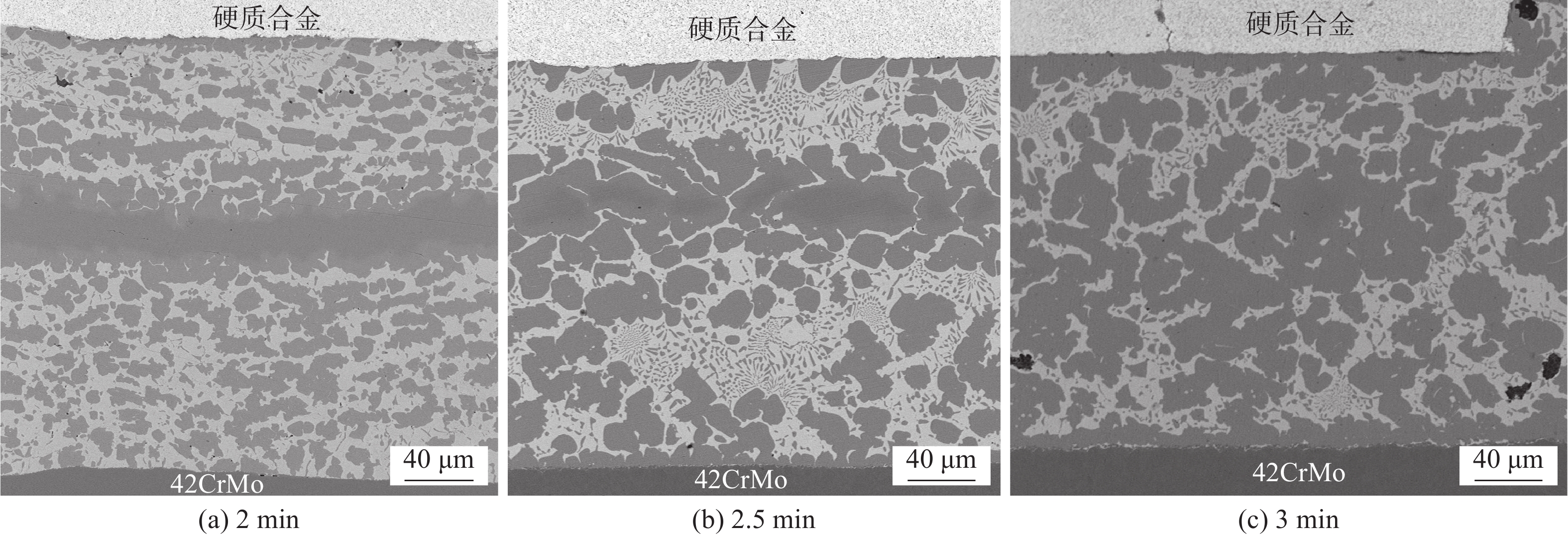
图 3 780 ℃不同保温时间钎缝微观组织
Figure 3. Microstructure of brazing seam with different time at 780 ℃. (a) 2 min; (b) 2.5 min; (c) 3 min; (d) 3.5 min; (e) 4 min
![]()
图 4 780 ℃保温不同时间钎缝元素分布
Figure 4. Elements distribution with different time at 780 ℃. (a) 2.5 min; (b) 3 min; (c) 3.5 min
![]()
图 5 800 ℃不同保温时间钎缝微观组织
Figure 5. Microstructure of brazing seam with different time at 800 ℃. (a) 2 min; (b) 2.5 min; (c) 3 min
![]()
图 6 780 ℃不同保温时间钎缝区域不同位置硬度变化
Figure 6. Hardness of brazing seam with different time at 780 ℃
![]()
图 8 780 ℃不同保温时间钎缝断口形貌
Figure 8. Fracture morphology of brazing seam with different time. (a) 2.5 min; (b) 4 min
![]()
图 9 空洞聚集形成韧窝断裂示意图
Figure 9. Schematic diagram of dimple fracture formed by cavity accumulation. (a) cavity growth; (b) cavity accumulation
表 1 42CrMo钢的主要化学成分(质量分数,%)
Table 1 Chemical composition of 42CrMo steel
C Cr Si Mo Mn Fe 0.42 1.05 0.27 0.2 0.65 余量  下载: 导出CSV
表 2 钎料合金化学成分(质量分数,%)
Table 2 Chemical compositions of filler metal
材料 Ag Cu Zn Ni Mn Co BAg40CuZnNi 40 30 27.8 2.2 — — CuMn2 — 98 — — 2 — BAg40CuZnNiMnCo 40 30 20.5 4 4.5 1
下载: 导出CSV
表 3 图3中标识位置能谱分析(质量分数,%)
Table 3 Energy spectrum analysis of identified locations in Fig. 3
位置 Ag Cu Zn Ni Mn Co 其它 A 6.24 67.04 17.48 4.7 1.74 1.21 余量 B 34.56 38.65 20.26 3.2 1.4 0.8 余量 C 9.67 66.12 17.55 3.67 1.41 0.55 余量 D 10.26 68.02 15.04 2.84 1.50 0.51 余量 E 0.63 94.29 0.57 0.16 2.26 0.13 余量 F 6.49 74.28 14.12 0.47 1.45 — 余量 G 9.26 57.03 19.33 4.06 1.13 — 余量
下载: 导出CSV
-
[1] Yin X H, Ma Q S, Cui B, et al. Current review on the research status of cemented carbide brazing: filler materials and mechanical properties[J]. Metals and Materials International, 2020, 2: 1 − 13.
[2] 秦建, 董显, 裴夤崟, 等. 高强韧CuZnNiMn纽扣钎料钎焊截齿接头组织与性能[J]. 焊接学报, 2019, 40(8): 96 − 103. Qin Jian, Dong Xian, Pei Yinyin, et al. Microstructure and properties of mining bit brazing joint employed by the high strength and ductility CuZnNiMn button materials[J]. Transactions of the China Welding Institution, 2019, 40(8): 96 − 103.
[3] 夏毅敏, 仝磊, 柏彬, 等. 盾构切刀硬质合金与钢基体钎焊残余应力[J]. 东北大学学报(自然科学版), 2020, 41(1): 101 − 107. Xia Yimin, Tong Lei, Bai Bin, et al. Residual stress in soldering and brazing between cemented carbide and steel substrate of shield machine cutters[J]. Journal of Northeastern University(Nature Science), 2020, 41(1): 101 − 107.
[4] Zhang X Z, Liu G W, Tao J N, et al. Brazing of WC–8Co cemented carbide to steel using Cu-Ni-Al alloys as filler metal: Microstructures and joint mechanical behavior[J]. Journal of Materials Science & Technology, 2018, 34(7): 1180 − 1188.
[5] Barrena M I, Gomez De Salazar J M, Matesanz L. Interfacial microstructure and mechanical strength of WC–Co/90MnCrV8 cold work tool steel diffusion bonded joint with Cu/Ni electroplated interlayer[J]. Materials and Design, 2010, 31(7): 3389 − 3394. doi: 10.1016/j.matdes.2010.01.050
[6] Kaiwa K, Yaoita S, Sasaki T, et al. Effects of Ni and Co additions to filler metals on Ag-brazed joints of cemented carbide and martensitic stainless steel[J]. Advanced Materials Research, 2014, 3130(922): 322 − 327.
[7] Wang H F, Chi L H, Chang H. Effect of tin content on the microstructure and property of brazed WC-Co/CrMo alloy steel joints[J]. Advanced Materials Research, 2008, 740(47): 596 − 599.
[8] Akbari Mousavi S A A, Sherafati P, Hoseinion M M. Investigation on wettability and metallurgical and mechanical properties of cemented carbide and steel brazed joint[J]. Advanced Materials Research, 2012, 1614(445): 759 − 764.
[9] Sui Y W, Luo H B, Yang Lü, et al. Influence of brazing technology on the microstructure and properties of YG20C cemented carbide and 16Mn steel joints[J]. Welding in the World, 2016, 60(6): 1269 − 1275. doi: 10.1007/s40194-016-0374-0
[10] Hasanabadi M, Shamsipur A, Najafisani H, et al. Interface structure and mechanical properties of brazing joints for WC using Ag-Cu-Zn-Ni-Mn filler metals[J]. Transactions of Nonferrous Metals Society of China, 2017, 27(12): 2638 − 2646. doi: 10.1016/S1003-6326(17)60292-9
[11] 马琳博, 王嘉琳. 硬质合金钎焊工艺分析[J]. 冶金与材料, 2021, 41(1): 185 − 186. Ma Linbo, Wang Jialin. Analysis of cemented carbide brazing process[J]. Metallurgy and Materials, 2021, 41(1): 185 − 186.
[12] 李远星, 张晓山, 朱宗涛, 等. Ni元素扩散行为对硬质合金/钢钎焊接头微观组织及力学性能的影响[J]. 稀有金属材料与工程, 2017, 46(4): 1120 − 1125. Li Yuanxing, Zhang Xiaoshan, Zhu Zongtao, et al. Effect of element Ni diffusion on microstructure and mechanical properties of brazed joints of cemented carbide and steel[J]. Rare Metal Materials and Engineering, 2017, 46(4): 1120 − 1125.
[13] Tillmann W, Sievers N. Feasibility study of fluxless brazing cemented carbides to steel[J]. Conference Series:Materials Science and Engineering, 2017, 181(1): 012007.
[14] 李永. 层状复合钎料制备工艺研究[D]. 北京:中国机械科学研究总院集团, 2013. Li Yong. Study of the manufacturing technology of layered composite brazing filler metal[D]. Beijing:China Academy of Machinery Science and Technology Group, 2013.
[15] Chao J, Chen H, Zhao X, et al. Microstructure and mechanical properties of brazing bonded WC-15Co/35CrMo joint using AgNi/CuZn/AgNi composite interlayers[J]. International Journal of Refractory Metal and Hard Materials, 2018, 70: 1 − 8. doi: 10.1016/j.ijrmhm.2017.08.021
[16] 周德敬, 尹林, 张新明, 等. 轧制复合/铝/不锈钢界面金属间化合物的生长动力学[J]. 中国有色金属学报, 2012, 22(9): 2461 − 2467. Zhou Dejin, Yin Lin, Zhang Xinming, et al. Growth kinetics of intermetallic compounds at aluminum/stainless steel interface bonded by rolling[J]. The Chinese Journal of Nonferrous Metals, 2012, 22(9): 2461 − 2467.
-
期刊类型引用(6)
1. 冯消冰,王建军,王永科,陈苏云,刘爱平. 面向大型结构件爬行机器人智能焊接技术. 清华大学学报(自然科学版). 2023(10): 1608-1625 .  百度学术
百度学术
2. 詹剑良,金浩哲. 六工位焊接电器盒系统设计. 机械制造文摘(焊接分册). 2022(02): 41-44 . 百度学术
3. 李建宇,倪川皓,江亚平,贾小磊. 高强钢小角度坡口深熔焊工艺. 机械制造文摘(焊接分册). 2022(05): 26-30 . 百度学术
4. 周利平,朵丛,韩永刚. 常见焊接接头的机器人焊接工艺设计. 科技视界. 2022(29): 101-103 . 百度学术
5. 刘云鸾,敖三三,罗震,相茜. 焊接与智能制造(下)——第25届北京·埃森焊接与切割展览会焊接国际论坛综述. 焊接技术. 2021(08): 1-3 . 百度学术
6. 洪妍,樊星. 北京·埃森焊接展之焊接智能化. 焊接技术. 2021(S1): 78-82 . 百度学术
其他类型引用(3)


计量
- 文章访问数: 324
- HTML全文浏览量: 72
- PDF下载量: 84
- 被引次数: 9
