
Effect of post welding heat treatment on corrosion behavior of NiCrMo-3 deposited metal
-
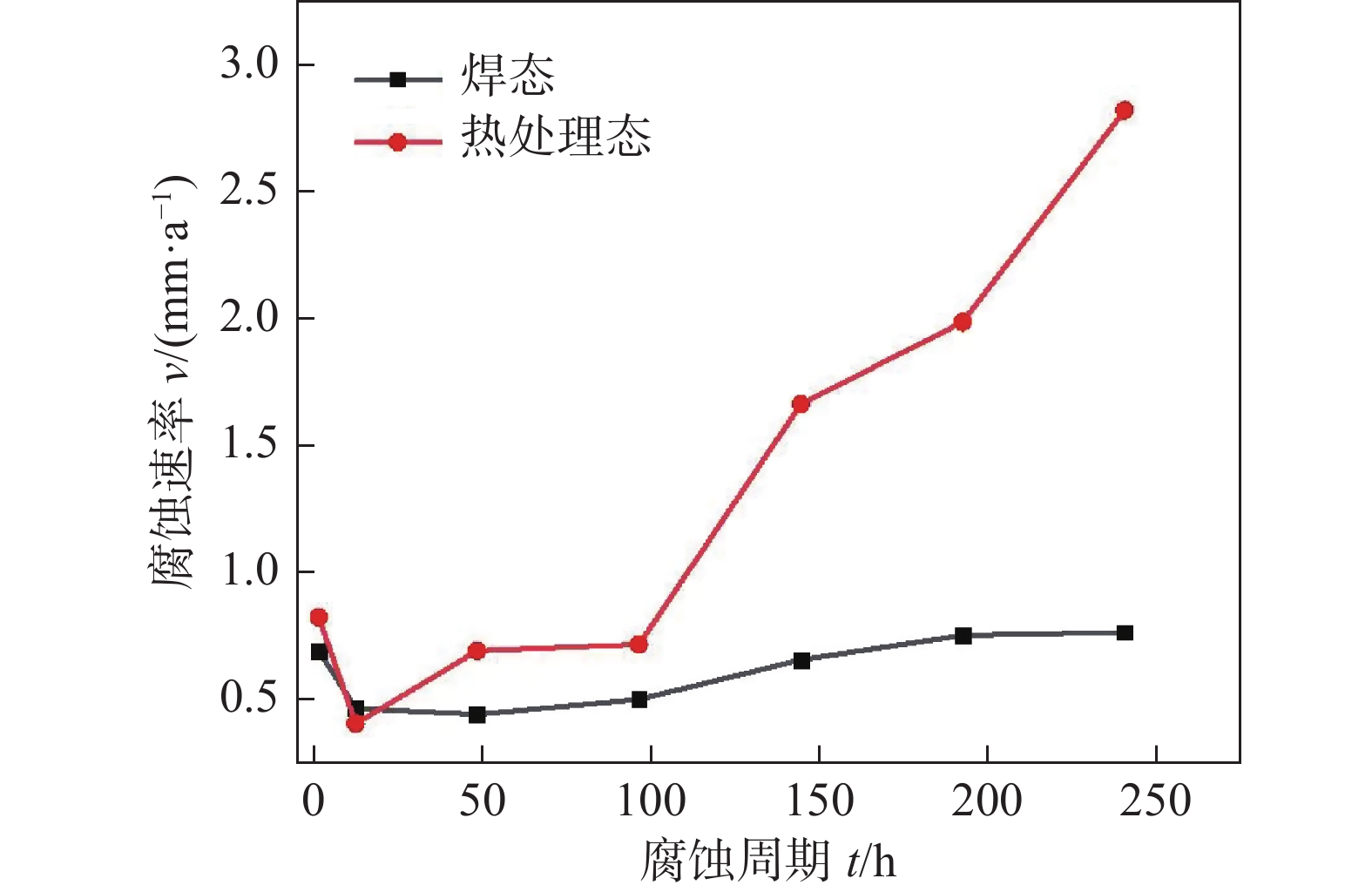
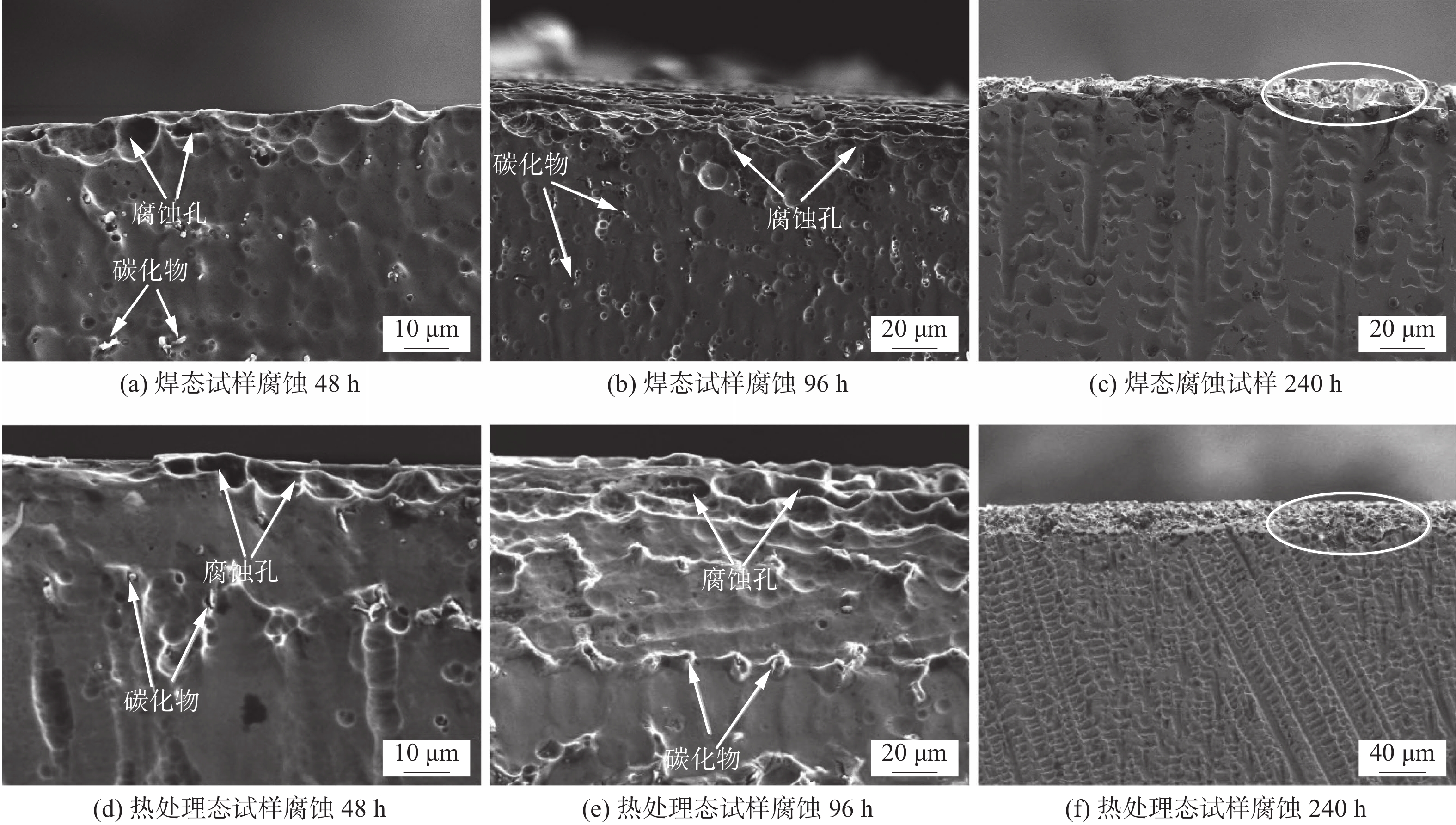
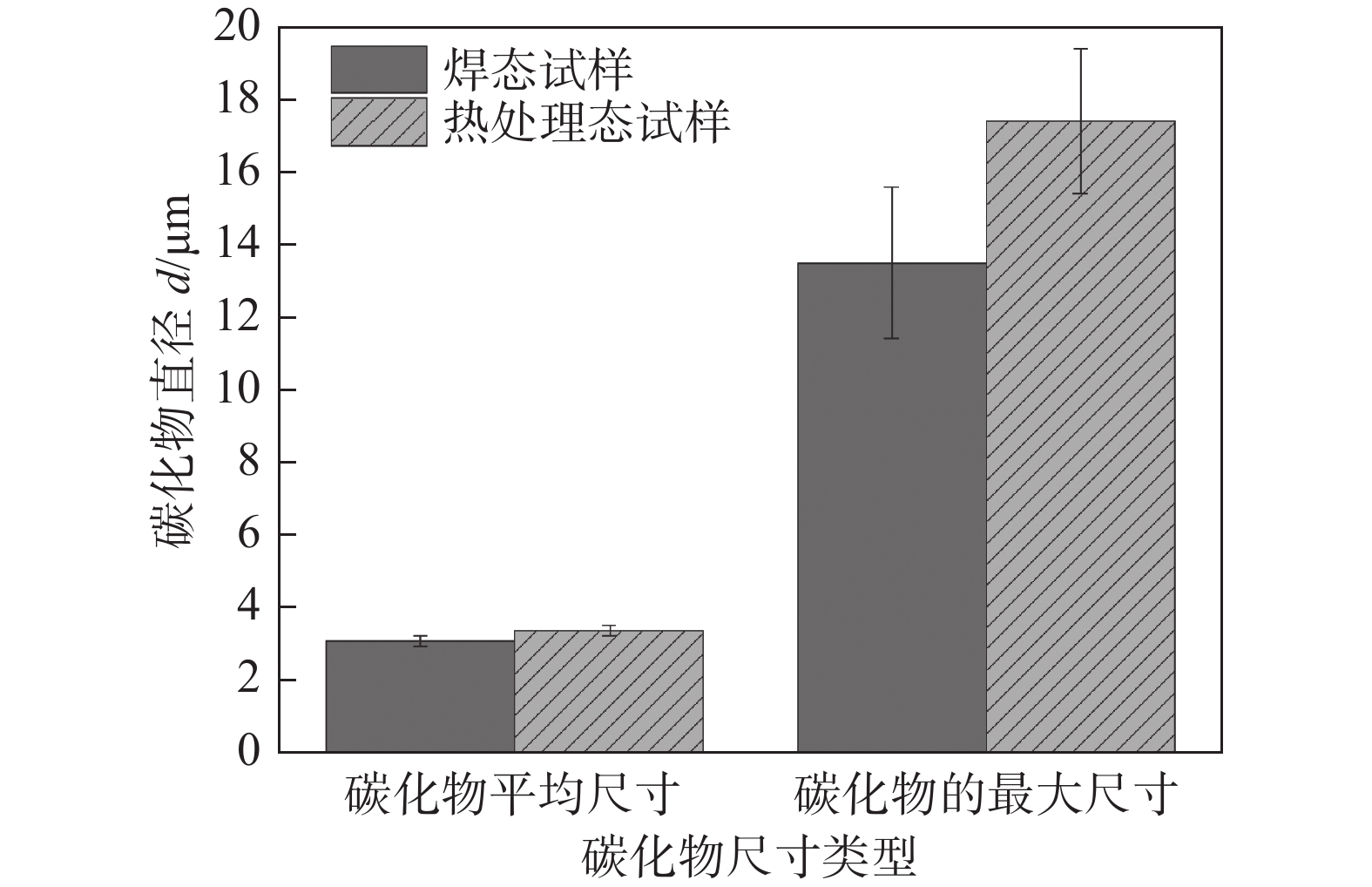
摘要: 以NiCrMo-3合金熔敷金属为研究对象,通过扫描电子显微镜、透射电子显微镜、X射线衍射仪等研究了原始焊态与690 ℃保温8 h热处理态熔敷金属的耐腐蚀性能差异.结果表明,与焊态试样相比,热处理试样具有良好的耐晶间腐蚀性能,在HNO3溶液中浸泡不同的时间发生了点蚀和晶间腐蚀;热处理态金属除了点蚀与晶间腐蚀还发生了部分枝晶间腐蚀行为.热处理后的试样由于NbC,Laves相数量及尺寸的增加导致腐蚀敏感性升高.析出相NbC,Laves相与基体的电位差导致在腐蚀介质作用下发生点蚀.晶界析出物导致Ni,Cr元素含量的降低,从而增加了熔敷金属晶间腐蚀敏感性.热处理后由于元素再分配导致枝晶间Nb,Mo等元素的富集和Ni,Cr等元素的贫化,引起枝晶间腐蚀.
-
关键词:
- NiCrMo-3熔敷金属 /
- 热处理工艺 /
- 析出相 /
- 耐腐蚀性能
Abstract: In this paper, the difference of corrosion resistance for NiCrMo-3 deposited metal with as-welded and as-PWHT (post welding heat treatment) at 690 ℃ for 8 h was investigated by scanning electron microscope, transmission electron microscopy and other characterization methods. The results show that the as-welded specimens have better intergranular corrosion resistance than that of as-PWHT specimens. Pitting corrosion and intergranular corrosion occur when the specimens were immersed in HNO3 solution for different times. In addition to pitting corrosion and intergranular corrosion, partial inter-dendrite corrosion occurs in as-PWHT deposited metal. The increase of the number and size of NbC and Laves phase leads to the increase of corrosion sensitivity of the specimens after heat treatment. The potential difference between precipitated phase NbC, Laves phase and matrix leads to pitting corrosion under the action of corrosive medium. The contents of Ni and Cr elements decrease due to grain boundary precipitates, which increased the intergranular corrosion sensitivity of deposited metal. After heat treatment, the elements redistribution leads to the enrichment of Nb, Mo elements and depletion of Ni, Cr elements, resulting in inter-dendrite corrosion. -
0. 序言
目前在工业制造领域,包括船舶建造、航空航天、轨道交通等,对高质量和高效率的新型焊接技术需求越来越迫切[1]. 实际生产中,等离子弧焊(plasma arc welding,PAW)和熔化极惰性气体保护焊(metal inert gas welding,MIG)由于前者的高能量密度[2]和后者的高柔性度、高效率[3]等优点在工业领域广泛应用. 旁路等离子体-MIG同轴复合电弧焊是一种新型工艺,既结合了这两种方法的优点,同时又可以通过调节旁路电流的大小精确控制电弧能量,从而能够适应不同加工场景及工作需求.
近年来,等离子-MIG复合电弧焊技术在国内外科研与工程领域屡见报道. Bai等人[4]对其熔滴过渡特性进行了研究,证明了亚射流过渡和射滴过渡是这种工艺最稳定的熔滴过渡方式;Yang等人[5-6]则对其工艺特性进行了试验研究,发现外侧的等离子电流有助于增加焊接熔深, 另外还对等离子体-MIG复合电弧的作用机制进行了研究,发现随着外部等离子电流的增加,电弧的稳定性得到加强,从而有助于进一步提高焊接质量;而在基于旁路电流的等离子体-MIG复合工艺方面,Miao等人[7]研究了其在加热和冷却过程中应力和变形的演变过程和作用机理,发现这种方法有利于缓解焊后残余应力和变形;需要指出的是旁路电流的概念是由美国肯塔基大学Zhang教授[8]首先提出,他们使用钨极作为分流电极分走MIG电弧的电流,以减少母材的热输入;Huang等人[9]提出将这一思想与等离子热丝工艺方法相结合进行镍基合金增材制造,发现熔覆层的高度随着旁路电流的增加而增加. 前期的研究报道主要集中在等离子-MIG同轴复合技术在改善焊接增材过程中材料成形、电弧及熔滴特性等方面的研究,但是基于旁路电流的等离子-MIG复合电弧和熔池的物理作用机制研究却未见报道.
文中借助商用流体计算软件Fluent,采用数值模拟[10]和物理试验相结合方法,针对旁路电流对等离子体-MIG复合电弧和耦合熔池影响机理进行深入研究,相关研究结果不仅丰富了电弧焊接理论及方法,同时为焊接过程能量精确控制提供更多可行性.
1. 数值模型
1.1 原理与计算域
图1是旁路等离子体-MIG复合工艺的原理和2D计算模型. 旁路等离子-MIG复合工艺的设计原理是通过与电源负极相连的等离子焊枪铜嘴和与电源正极相连的焊丝间形成分流弧,分走焊丝与母材间主路电弧的电流,如图1a所示, 为了防止铜嘴过热烧损,铜嘴采用循环水冷却; 图1b为旁路等离子-MIG复合焊接电弧与熔池的作用原理;图1c为根据原理设计的数值模型包括焊丝区、铜嘴区、电弧区和母材区. 模型的尺寸为24 mm × 12.8 mm(KJ × JH). 焊丝的半径为0.6 mm,铜嘴极的尺寸设置为1 mm,焊丝端部距离母材上表面的距离为5 mm,母材的厚度为6 mm,铜嘴出口半径1.5 mm,以上参数均是根据物理试验情况设定. 全计算域采用四边形网格离散,由于焊丝下方、铜嘴下方以及气液交界面的区域传热传质行为较为剧烈,因此采用较小的网格尺寸0.1 mm × 0.1 mm,为了提高计算效率,其它部分的网格尺寸相对粗化.
![]() 图 1 旁路等离子-MIG复合工艺原理及计算域Figure 1. Principle and calculation domain of plasma-MIG hybrid technology. (a) principle; (b) hybrid arc and molten pool; (c) calculation domain
图 1 旁路等离子-MIG复合工艺原理及计算域Figure 1. Principle and calculation domain of plasma-MIG hybrid technology. (a) principle; (b) hybrid arc and molten pool; (c) calculation domain1.2 基本假设
为了合理地计算、分析和证明旁路等离子-MIG复合电弧和耦合熔池的复杂流体动力学行为,建立了如下重要假设.
(1) 设置的模型是轴向对称的.
(2) 流体是不可压缩的牛顿流体,流体流动为层流.
(3) 在计算过程中,旁路等离子体-MIG复合电弧直接作用于熔池的上表面,这里不考虑熔池变形.
(4) 气体为纯氩气,其物理特性包括密度、比热、热导率等随温度变化,高温等离子体属于局部热动力平衡(LTE).
(5) 不考虑金属液滴与电弧和熔池的相互作用.
1.3 控制方程
计算涉及的控制方程主要包括连续方程、动量守恒、能量守恒方程. 二维坐标系下, 连续方程为[11]
$$ \frac{{\partial \rho }}{{\partial t}} + \frac{1}{r}\frac{\partial }{{\partial r}}(\rho ru) + \frac{\partial }{{\partial a}}(\rho v) = 0 $$ (1) 式中:ρ为密度;t为时间;u和v分别为径向r和轴向a的速度.
径向和轴向的动量守恒方程为[11]
$$ \begin{split} & \frac{{\partial (\rho u)}}{{\partial t}} + \frac{1}{r}\frac{\partial }{{\partial r}}(\rho ruu) + \frac{\partial }{{\partial a}}(\rho uv) = - \frac{{\partial p}}{{\partial r}} - {j_{\text{a}}}{B_{{\rm{\theta}}}} - 2\mu \frac{u}{{{r^2}}} +\\&\qquad \frac{1}{r}\frac{\partial }{{\partial r}}(2r\mu \frac{{\partial u}}{{\partial r}}) + \frac{\partial }{{\partial a}}\left(\mu \frac{{\partial u}}{{\partial a}} + \mu \frac{{\partial v}}{{\partial r}}\right) + {S_{\text{r}}} \end{split} $$ (2) $$ \begin{split} & \frac{{\partial (\rho v)}}{{\partial t}} + \frac{1}{r}\frac{\partial }{{\partial r}}(\rho ruv) + \frac{\partial }{{\partial a}}(\rho vv) = - \frac{{\partial p}}{{\partial a}} - {j_{\text{r}}}{B_{\text{θ}}} - \rho g +\\&\qquad \frac{1}{r}\frac{\partial }{{\partial r}}(r\mu \frac{{\partial u}}{{\partial a}} + r\mu \frac{{\partial v}}{{\partial r}}) + \frac{\partial }{{\partial a}}(2\mu \frac{{\partial u}}{{\partial a}}) + {S_{\text{a}}} \end{split}$$ (3) 式中:p为压力;µ为动态粘度;Sr和Sa为径向和轴向源项;Bθ为磁场强度,可由麦克斯韦方程得到;ja和jr为轴向和径向电流密度.
能量守恒方程为[11]
$$ \begin{split} & \frac{{\partial \left(\rho H\right)}}{{\partial t}} + \frac{1}{r}\frac{\partial }{{\partial r}}\left(\rho ruH\right) + \frac{\partial }{{\partial a}}\left(\rho vH\right) =\\&\frac{1}{r}\frac{\partial }{{\partial r}}\left(r\frac{k}{{{C_{\text{p}}}}}\frac{{\partial T}}{{\partial r}}\right) + \frac{\partial }{{\partial a}}\left(\frac{k}{{{C_{\text{p}}}}}\frac{{\partial T}}{{\partial a}}\right) + {S _{\text{E}}} \end{split}$$ (4) 式中:H为焓;k为导热系数;T为温度;SE为能量源项.
1.4 界面追踪
焓-孔技术[11]是用来处理固相向液相转化过程中的热量变化,可以表示为
$$ H = h + \Delta H = \int_{{T_\infty }}^T {{C_{\text{p}}}} {\rm{d}}T + {f_{\text{l}}}L $$ (5) $$ {f_{\text{l}}} = \left\{ {\begin{array}{*{20}{l}} 0&{T \leqslant {T_{\text{s}}}} \\ {(T - {T_{\text{s}}})/({T_{\text{l}}} - {T_{\text{s}}})},&{{T_{\text{s}}} < T < {T_{\text{l}}}} \\ 1&{T \geqslant {T_{\text{l}}}} \end{array}} \right. $$ (6) 式中:h为金属的焓;Cp为比热;fl为液相分数;L为潜热;Ts和Tl分别为固相和液相温度.
1.5 源项
源项包括动量和能量源项,动量源项包括热浮力、马兰戈尼力,分别表示为[11]
$$ {S_{\text{r}}} = - \frac{\mu }{K}u,{S_{\text{a}}} = - \frac{\mu }{K}v + \rho g\beta (T - {T_{{\text{melt}}}}) $$ (7) $$ K = \frac{{f_{\text{l}}^{\text{3}}}}{{A{{(1 - {f_{\text{l}}})}^2}}} $$ (8) $$ \tau = \mu \frac{{\partial V}}{{\partial n}} = - \frac{{{\rm{d}}\gamma }}{{{\rm{d}}T}} \cdot \frac{{\partial T}}{{\partial n}} $$ (9) 式中:β为热膨胀系数;A为糊状区常数;τ为马兰戈尼力;γ为表面张力系数;n为局部表面的切线方向. 电弧区的能量源项为
$$ {S _{\text{E}}} = \frac{{j_{\text{r}}^2 + j_{\text{a}}^2}}{{{\sigma _{\text{e}}}}} + \frac{5}{2}\frac{\sigma }{e}\left({j_{\text{a}}}\frac{{\partial T}}{{\partial a}} + {j_{\text{r}}}\frac{{\partial T}}{{\partial r}}\right) - H_{{\text{los}}} $$ (10) 式中:σe为电导率;Hlos为热损失. 另外界面处的能量源项包括阴极中的电子激活、能量传递以及其表面的热损失被添加,即
$$ S = - \left| {{j_{\text{c}}}} \right|{\phi _{\text{w}}} + {q_{\text{c}}} - \sigma \varepsilon {T^4} $$ (11) 式中:jc为阴极表面的电流密度;ϕw为阴极的功函数;qc为传导能量;σ为Stefan-Boltzmann常数;ε为辐射率.
1.6 边界条件
阳极的边界(AB,BC)、等离子铜嘴的边界(DE,EF,FG)以及两个气体速度入口(CD,GH)的温度被设定为1 000 K,KA为轴向对称轴,HI为压力-出口边界,在基底区域的边界(IJ和JK)有两个热交换过程,即对流和辐射,可以表示为[12]
$$ q = {h_{{\text{conv}}}}(T - {T_{{\text{amb}}}}) + \sigma \varepsilon ({T^4} - T{_{{\text{amb}}}}^4) $$ (12) 式中:hconv为对流传热系数;Tamb为环境温度.
1.7 材料模型
试验使用的母材是典型船用5083铝合金,其热物理性能[13]如表1所示. 气相是纯氩气且不考虑空气的影响[14],其热物理性能见文献[15].
表 1 5083铝合金热物理性能Table 1. 5083 aluminum alloy property parameters环境温度Tamb/K 固相线温度Ts/K 液相线温度Tl/K 热传导率(固态)
ks/(W·m−1·K−1)热传导率(液态)
k1/(W·m−1·K−1)比热容(固态)
cs/(J·kg−1·K−1)比热容(液态)
c1/(J·kg−1·K−1)粘度μ/(kg·m−1·K−1) 密度
ρ/(103 kg·m3)300 847 933 235 90 1 050 1 200 0.004 2 2.66 辐射率
ε磁导率
μ0/(10−6 H·m−1)相变潜热
L/(105 J·kg−1)线膨胀系数
α/10−5K−1电导率
σe/ (107Ω−1·m−1)传热系数
k/(W·m−2·K−1)功函数
ϕw/eV表面张力温度梯度系数γ/(10−4 N·m−1·K−1) 0.15 1.26 3.87 2.3 1.7 20 3.0 -1.55 2. 计算结果与分析
2.1 复合电弧与耦合熔池演变过程
计算过程采用的工艺参数如表2所示. 计算结果如图2所示,其中图2a为施加旁路电流时的复合电弧和耦合熔池的演变过程,图2b为不施加旁路电流时的电弧和耦合熔池的演变过程. 可以看出t = 0.2 s时,这两者的电弧和熔池都处于长大状态,其中图2a中的母材仍处于尚未熔化状态;t = 0.5 s时,二者的电弧都已经趋于稳定,但熔池的尺寸随着热通量的增加还在继续增长; 随着时间的增加,t = 0.7 s时,熔池内部的液态金属流动行为已经相对剧烈;t = 1.2 s时,图2b的母材已经熔透,而图2a的熔池形态还处于稳定的状态.
表 2 计算过程工艺参数Table 2. Process parameters序号 主路电流
I1/A旁路电流
I2/A离子气体流量
Q1/(L·min−1)保护气体流量
Q2/(L·min−1)1 140 15 1 15 2 140 0 1 15 ![]() 图 2 旁路等离子-MIG复合电弧与熔池演变过程Figure 2. Plasma-MIG hybrid arc and molten pool evolution. (a) with bypass-current; (b) without bypass-current
图 2 旁路等离子-MIG复合电弧与熔池演变过程Figure 2. Plasma-MIG hybrid arc and molten pool evolution. (a) with bypass-current; (b) without bypass-current从计算结果来看,施加旁路电流时,母材的热输入降低效果是明显的,此外还可以看出施加旁路电流后,电弧的高温等离子体形态产生了明显的变化,这种变化主要体现在电弧下方出现了明显的收缩趋势,而电弧加热面积的减少也是母材热输入降低的主要原因之一. 由于进入电弧区的气相带电粒子部分向阴极扩散,导致图2a的电弧自身的热效应也有所降低,这可以从图3的电弧最高温度曲线得出. 相比图2b所示结果,图2a的电弧最高温度从初始时刻就较低,这个最大温差接近1 000 K,且随着时间变化一直稳定存在,如图3复合电弧温度曲线所示. 差异的电弧行为最终导致了熔池内部液态金属的对流换热行为也产生了差异.
![]() 图 3 电弧最高温度与熔池最大流速随时间变化趋势Figure 3. Trend of maximum arc temperature and maximum melt pool flow velocity over time
图 3 电弧最高温度与熔池最大流速随时间变化趋势Figure 3. Trend of maximum arc temperature and maximum melt pool flow velocity over time整体来看,熔池内部液态金属的流速均呈现先增加后稳定的变化趋势,且施加旁路电流时熔池内部液态金属的流速更低,如图3中最大流速曲线所示. 当施加旁路分流时,从初始时刻到t = 0.2 s,母材几乎不熔化,而不施加旁路分流时,母材已经熔化,且液相金属的最大流速达到0.42 m/s;t = 0.5 s,这两者的液态金属流速基本达到最大值,以后时刻增长幅度都很小;但是随着热输入增加,母材的活化金属量继续增加,熔池的面积继续增大,不施加旁路电流时的母材金属活化速度要远远高于施加旁路电流时,这可以通过图2中母材熔池面积的增加趋势看出,最终t = 1.2 s,不施加旁路电流时,母材出现熔透现象,而施加旁路电流时,熔池仍处于稳定状态.
2.2 电弧—熔池界面热通量分析
图4为电弧与熔池的交界面处的有效热通量对比情况. 由于电弧的本质是高温等离子体,因而在焊接加工过程中电弧本身要向周围低温环境散失能量,而真正由电弧传递给母材的能量是焊接加工过程中的有效能量,即除去热损失而真正形成熔池的能量,此处通过有效热通量的方式对有无旁路电流施加时有效能量区别进行对比分析. 从计算结果来看,当无旁路电流施加时,电弧与熔池界面处的有效热通量整体更高, 但是当施加旁路电流时,界面中心的能量峰值更高,这是因为旁路电流施加后,电弧的下部分产生压缩态,因而在中心部分的能量密度更高,但是由于部分带电粒子没有向母材运动,趋向母材运动的能量粒子水平更低,因而随着径向距离的增加,能量的分布快速下降,即有效加热面积减少,整体的能量水平也就更低.
![]() 图 4 复合电弧与耦合熔池界面处的有效热通量对比Figure 4. Comparison of the effective heat flux at the interface between the hybrid arc and the molten pool
图 4 复合电弧与耦合熔池界面处的有效热通量对比Figure 4. Comparison of the effective heat flux at the interface between the hybrid arc and the molten pool热量由电弧通过气液交界面向母材传递,经过一段时间的能量演变和积累逐渐形成熔池. 图5为 t = 1.2 s 时熔池内部液态金属径向和轴向的流速以及它们对熔池尺寸的影响对比. 在轴向上,液态金属在温度梯度的作用下由表面向下运动,在一定范围内形成回流,从计算结果可以看出,当旁路电流施加时,轴向的液态金属最大流动速度明显降低,最终也导致了熔深尺寸的下降; 在径向上,液态金属的回流驱动力还包括马兰戈尼力,从计算结果可以看出径向上的液态金属回流运动最大速度整体水平较高;当施加旁路电流时,径向上的液态金属流动速度相也有所降低,最终也导致熔池的熔宽尺寸有所下降. 整体来看,旁路电流的施加有减小熔池尺寸的作用,在熔深方向的减小程度更明显,这是因为旁路电流间接导致电弧中心附近能量传递水平下降剧烈,例如在距离中心1.5 mm左右,有效热通量已经下降了约60 × 106 W/m2,因此母材积累的热量水平也就下降,液化的母材体积更少, 以上计算结果和分析说明这种新型工艺在电弧能量精确调控和减少母材热输入方面是有优势的.
![]() 图 5 熔池内部液态金属流速对熔池尺寸的影响Figure 5. Influence of the liquid metal flow velocity on sizes of the molten pool
图 5 熔池内部液态金属流速对熔池尺寸的影响Figure 5. Influence of the liquid metal flow velocity on sizes of the molten pool2.3 电弧与熔池电磁效应分析
图6为t = 1.2 s时整个计算模型内,包括电弧区和母材区的电流密度矢量分布. 从计算结果来看,当施加旁路电流时,在焊丝端和分流极端都有较高的电流密度分布,且矢量方向相反,这与试验设置是吻合的.
![]() 图 6 计算域内电流密度矢量分布情况对比Figure 6. Comparison of the current density vector distribution in the calculation domain. (a) with bypass-current; (b) without bypass-current
图 6 计算域内电流密度矢量分布情况对比Figure 6. Comparison of the current density vector distribution in the calculation domain. (a) with bypass-current; (b) without bypass-current在电弧区,无论是否施加旁路电流,最大电流密度区均出现在焊丝极下方的电弧中心区,且方向均是由焊丝极指向母材极,但是最高电流密度的数值有所不同. 当施加旁路电流时,电弧区的最大电流密度为1.32 × 10⁸ A/m2,熔池区的最大电流密度为1.3 × 107 A/m2;不施加旁路电流时,电弧区的最大电流密度为1.71 × 108 A/m2,熔池区的最大电流密度为2.25 × 107 A/m2. 旁路电流施加前后电弧区最大电流密度相差接近1.3倍,而母材区相差约1.7倍,这是由于部分带电粒子在旁路电流施加前后分别向分流电极和向母材极运动的结果,而电流密度的不同又会对磁场强度及分布产生影响.
图7为t = 1.2 s时,计算域内电磁矢量的分布和数值对比情况. 从计算结果来看,无论是否施加旁路电流,最大磁力的位置和方向并没有改变,但是其在电弧区的数值因为旁路电流的施加从7.1 × 10⁶ N/m3下降到5.1 × 106 N/m3;而其在熔池区的数值从8.4 × 106 N/m3下降到5.6 × 106 N/m3,下降的趋势基本接近,这说明旁路电流的施加不会改变最大磁场强度的方向,但会降低电弧和熔池内部的电流密度的数值,进而降低电磁力的数值,即旁路电流有弱化磁场作用.
![]() 图 7 计算域内电磁矢量分布情况对比Figure 7. Comparison of electromagnetic vector distribution in the calculation domain. (a) with bypass-current; (b) without bypass-current
图 7 计算域内电磁矢量分布情况对比Figure 7. Comparison of electromagnetic vector distribution in the calculation domain. (a) with bypass-current; (b) without bypass-current2.4 试验验证
图8为施加旁路分流时的等离子-MIG复合电弧和熔池在t = 1.2 s时的计算与试验结果对比,其中类似的双侧分流机制下的高温等离子体图像已经由兰州理工大学石玗教授团队[15]成功拍摄(图8左上所示). 从对比结果看出电弧下方的等离子体具有更高的温度,而两侧的分流弧的等离子体温度较低,图像中其亮度也较弱. 熔池的试验结果如图8左下所示. 总体来看,模拟结果与试验结果在一定程度上能够匹配,但是也存在一些误差:其一是电弧根部的发散;其二是熔宽尺寸误差约0.5 mm, 造成这些误差的原因是由于没有考虑熔滴的影响,其次数据处理过程也会产生一些误差.
3. 结论
(1) 其它试验条件相同,施加旁路电流后,电弧有压缩趋势,此外复合电弧和母材交界面处的有效热通量整体减少.
(2) 施加旁路电流后,熔池内部液态金属在轴向和径向上的回流速度有所降低,最终导致熔池面积减小.
(3) 旁路电流的施加使电弧和熔池的电流密度下降约23%和42%,因此导致等离子-MIG复合电弧和耦合熔池的最大电磁力数值减小约28%和33%,但其方向没有改变.
-
![]()
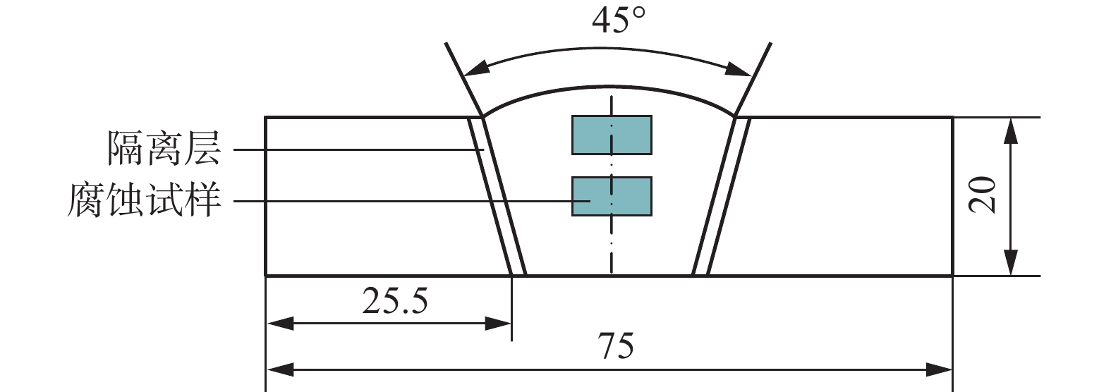
图 1 金相和腐蚀试验取样示意图(mm)
Figure 1. Schematic diagram of specimen sampling of metallographic test and corrosion test
![]()
图 3 焊态和热处理态熔敷金属的组织
Figure 3. Microstructure of deposited metals with as-welded and as-PWHT. (a) dendrite structure with as-welded sample; (b) SEM morphology with as-welded sample; (c) SEM morphology of precipitated phase with as-welded sample; (d) dendrite structure with as-PWHT sample; (e) SEM morphology with as-PWHT sample; (f) SEM morphology of precipitated phase with as-PWHT sample; (g) TEM morphology of MC phase; (h) TEM morphology of Laves phase
![]()
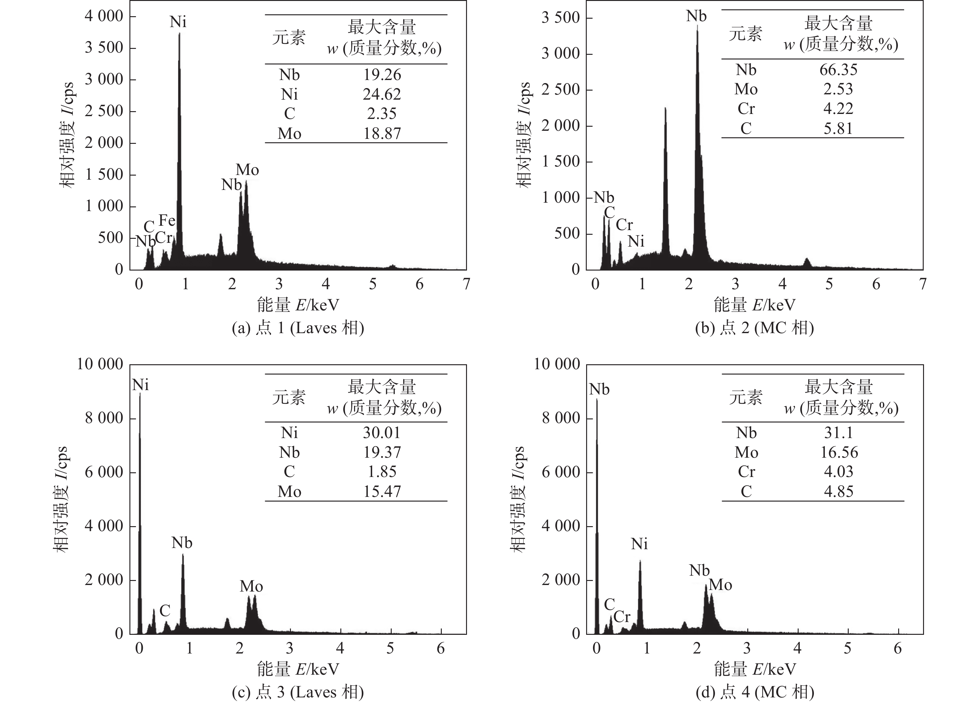
图 4 析出相成分分析
Figure 4. Compositions analysis of precipitated phase. (a) point 1 (Laves phase); (b) point 2 (MC phase); (c) point 3 (Laves phase); (d) point 4 (MC phase)
![]()
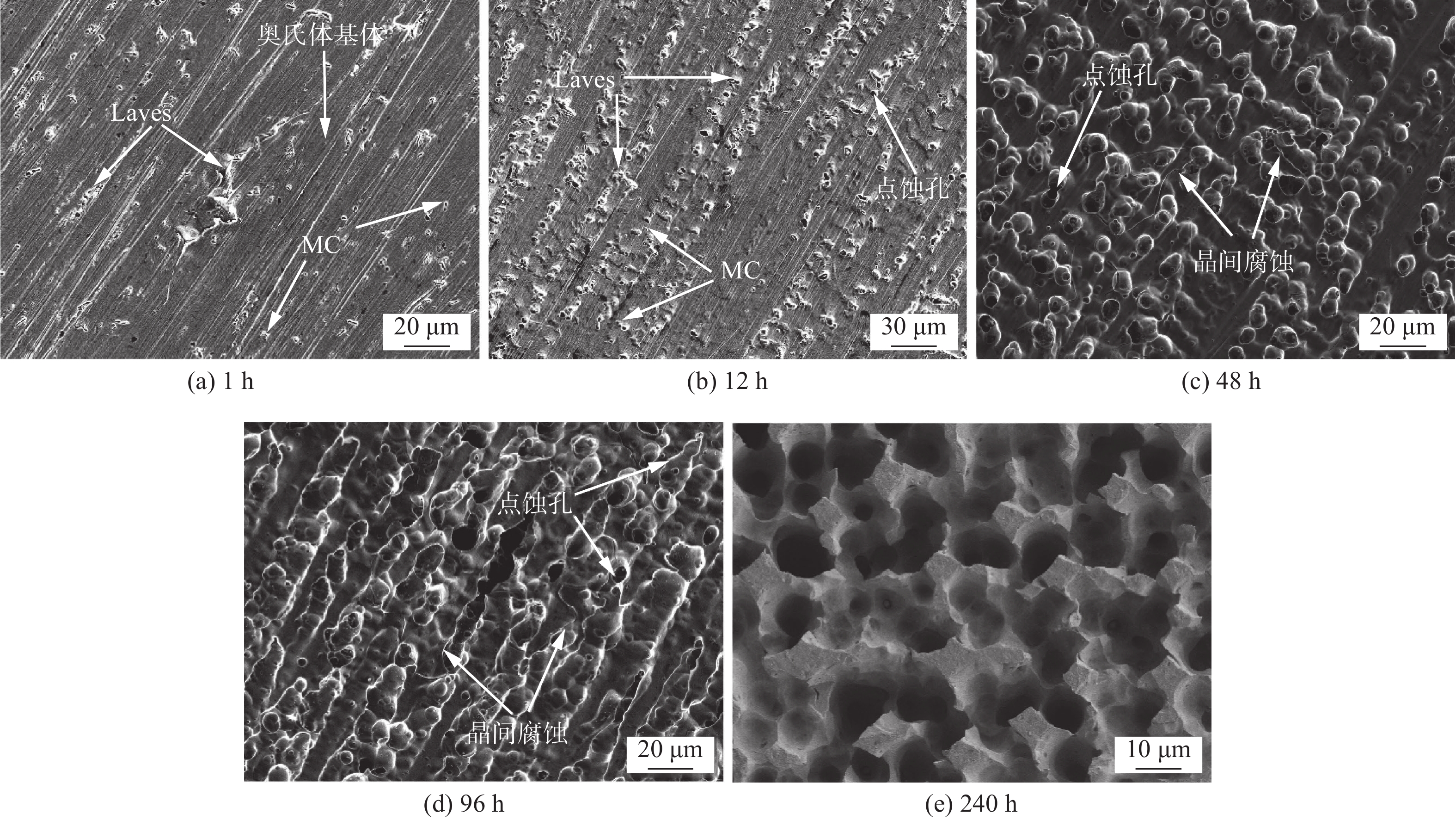
图 5 焊态试样腐蚀表面形貌
Figure 5. Corrosion surface morphology of as-welded samples. (a) 1 h; (b) 12 h; (c) 48 h; (d)96 h; (e) 240 h
![]()
图 6 热处理试样腐蚀表面形貌
Figure 6. Corrosion surface morphology of as-PWHT samples. (a) 1 h; (b) 12 h; (c) 48 h; (d) 96 h; (e) 240 h
![]()
图 8 不同腐蚀时间下焊态与热处理态试样腐蚀截面SEM图
Figure 8. SEM images of corrosion sections of as-welded and as-PWHT specimens at different corrosion times. (a) 48 h of as-welded sample; (b) 96 h of as-welded sample; (c) 240 h of as-welded sample; (d) 48 h of the as-PWHT sample; (e) 96 h of the as-PWHT sample; (f) 240 h of the as-PWHT sample
表 1 NiCrMo-3熔敷金属的化学成分(质量分数,%)
Table 1 Chemical compositions of NiCrMo-3 deposited metal
Cr Mo C Si S Nb Al Ti Fe Ni 22.240 8.550 0.012 0.280 0.005 3.390 0.055 0.060 1.000 余量  下载: 导出CSV
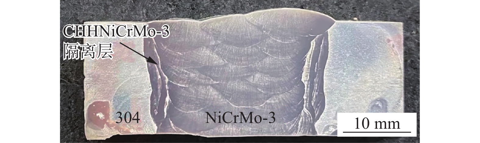
表 2 焊接工艺参数
Table 2 Welding process parameters
位置 焊接方法 焊接电流I/A 电弧电压U/V 焊接材料 焊条/焊丝直径d/mm 焊接速度v/(cm·min−1) 隔离层 手工堆焊 135 25 ~ 26 CHHNiCrMo-3 4.0 − 填充层 埋弧焊 300 30 ~ 32 ERNiCrMo-3 2.4 40
下载: 导出CSV
-
[1] Sims C T, Stoloff N S, Hagel W C. Superalloys II[M]. New York: Wiley, 1987.
[2] Xu Tao, Wang Zishun, Shi Yonghua. Investigation of C276 alloy and 316L SS TIG welded joints with ERNiCrMo-4 and ER304 welding wires[J]. China Welding, 2021, 30(4): 9 − 16.
[3] Wang L, Li H, Liu Q, et al. Effect of sodium chloride on the electrochemical corrosion of Inconel 625 at high temperature and pressure[J]. Journal of Alloys & Compounds, 2017, 703: 523 − 529.
[4] Abioye T E, Mccartney D G, Clare A T. Laser cladding of Inconel 625 wire for corrosion protection[J]. Journal of Materials Processing Technology, 2014, 217: 232 − 240.
[5] Fesharaki M N, Shoja-Razavi R, Mansouri H A, et al. Evaluation of the hot corrosion behavior of Inconel625 coatings on the Inconel 738 substrate by laser and TIG cladding techniques[J]. Optics & Laser Technology, 2019, 111: 744 − 753.
[6] Guo L. Effect of heat treatment temperatures on microstructure and corrosion properties of Inconel 625 weld overlay deposited by PTIG[J]. International Journal of Electrochemical Science, 2016, 97: 5507 − 5519.
[7] Lemos G V B, Farina A B, Nunes R M, et al. Residual stress characterization in friction stir welds of alloy 625[J]. Journal of Materials Research and Technology, 2019, 8(1): 2528 − 2537.
[8] Guo L, Xiao F, Wang F, et al. Influence of heat treatments on microstructure, mechanical properties and corrosion resistance of Inconel 625 overlay cladded using PTIG[J]. Materials Research Express, 2020, 7(9): 096517. doi: 10.1088/2053-1591/abb858
[9] Song K H, Nakata K. Effect of precipitation on post-heat-treated Inconel 625 alloy after friction stir welding[J]. Materials & Design, 2010, 31(6): 2942 − 2947.
[10] Marchese G, Lorusso M, Parizia S, et al. Influence of heat treatments on microstructure evolution and mechanical properties of Inconel 625 processed by laser powder bed fusion[J]. Materials Science & Engineering: A, 2018, 729: 64 − 75. doi: 10.1016/j.msea.2018.05.044
[11] Mittra J, Banerjee S, Tewari R, et al. Fracture behavior of Alloy 625 with different precipitate microstructures[J]. Materials Science & Engineering: A, 2013, 574: 86 − 93.
[12] 郭枭, 徐锴, 霍树斌, 等. 镍基合金焊丝GTAW熔敷金属凝固偏析行为[J]. 焊接学报, 2019, 40(7): 105 − 108. Guo Xiao, Xu Kai, Huo Shubin, et al. Investigation on the solidification segregation behavior of GTAW nickel alloy deposited metal[J]. Transactions of the China Welding Institution, 2019, 40(7): 105 − 108.
[13] Je S G, Kim D H, Yoo S C, et al. Asymmetric magnetic domain-wall motion by the Dzyaloshinskii-Moriya interaction[J]. Physical Review B, 2013, 88(21): 214401. doi: 10.1103/PhysRevB.88.214401
[14] Mathew M. D, Parameswaran P, Rao K. Microstructural changes in alloy 625 during high temperature creep[J]. Materials Characterization, 2008, 59(5): 508 − 513. doi: 10.1016/j.matchar.2007.03.007
[15] Qi H, Azer M, Ritter A. Studies of standard heat treatment effects on microstructure and mechanical properties of laser net shape manufactured Inconel 718[J]. Metallurgical and Materials Transactions A, 2009, 40(10): 2410 − 2422.
[16] Shimada M, Kokawa H, Wang Z J, et al. Optimization of grain boundary character distribution for intergranular corrosion resistant 304 stainless steel by twin-induced grain boundary engineering[J]. Acta Materialia, 2002, 50(9): 2331 − 2341. doi: 10.1016/S1359-6454(02)00064-2
[17] Kobayashi S, Kobayashi R, Watanabe T. Control of grain boundary connectivity based on fractal analysis for improvement of intergranular corrosion resistance in SUS316L austenitic stainless steel[J]. Acta Materialia, 2016, 102: 397 − 405. doi: 10.1016/j.actamat.2015.08.075
[18] Xu L, Zhang J, Han Y, et al. Insights into the intergranular corrosion of overlay welded joints of X65-Inconel 625 clad pipe and its relationship to damage penetration[J]. Corrosion Science, 2019, 160: 108169.
[19] Lin P, Palumbo G, Erb U, et al. Influence of grain boundary character distribution on sensitization and intergranular corrosion of alloy 600[J]. Scripta Metallurgica Et Materialia, 1995, 33(9): 1387 − 1392. doi: 10.1016/0956-716X(95)00420-Z
[20] Kjc A, Scy B, Sk C, et al. Microstructural evolution and corrosion behaviour of thermally aged dissimilar metal welds of low-alloy steel and nickel-based alloy[J]. Corrosion Science, 2019, 153: 138 − 149. doi: 10.1016/j.corsci.2019.03.032
[21] Zhang S, Li H, Jiang Z, et al. Effects of Cr and Mo on precipitation behavior and associated intergranular corrosion susceptibility of super austenitic stainless steel S32654[J]. Materials Characterization, 2019, 152: 141 − 150. doi: 10.1016/j.matchar.2019.04.010
[22] Xing X, Di X, Wang B. The effect of post-weld heat treatment temperature on the microstructure of Inconel 625 deposited metal[J]. Journal of Alloys & Compounds, 2014, 593: 110 − 116. doi: 10.1016/j.jallcom.2013.12.224
[23] Guo L, Xiao F, Wang F, et al. Effect of post-weld heat treatment temperatures on microstructure, intergranular corrosion resistance, and mechanical properties of 4130 steel with Inconel 625 weld overlay[J]. Journal of Failure Analysis and Prevention, 2021, 21(5): 1775 − 1783.
[24] Rajani H, Mousavi S, Sani F M. Comparison of corrosion behavior between fusion cladded and explosive cladded Inconel 625/plain carbon steel bimetal plates[J]. Materials & Design, 2013, 43(1): 467 − 474.
[25] Zhao P. Application of molybdenum in stainless steel[J]. China Molybdenum Industry, 2004, 28(5): 3 − 10.
[26] Peng Q J, Yamauchi H, Shoji T. Investigation of dendrite-boundary microchemistry in alloy 182 using auger electron spectroscopy analysis[J]. Metallurgical and Materials Transactions A, 2003, 34(9): 1891 − 1899.


计量
- 文章访问数: 146
- HTML全文浏览量: 14
- PDF下载量: 38
