
Optimization of process parameters for electron beam butt welding of HR-2 hydrogen resistant steel based on response surface method
-
摘要: 为解决HR-2抗氢钢电子束插接焊有效熔深不足、焊缝处开裂等问题,采用BBD设计试验方案,基于响应面法建立了HR-2抗氢钢电子束插接焊焊接工艺参数(聚焦电流、焊接速度、束流、倾斜角度)与预测响应值(有效熔深、接头抗剪承载力)之间的统计模型. 根据有效熔深和接头抗剪承载力的要求优化焊接工艺参数,并通过优化电子束焊接工艺参数来预测电子束插接焊的有效熔深和接头抗剪承载力,实现焊缝截面形貌与接头强度的最佳组合. 结果表明,模型拟合度较好,有效熔深预测值比实测值高1.17%,接头抗剪承载力预测值比实测值高2.63%,得到较优的焊接参数为:聚焦电流2.46 A,焊接速度10.00 mm/s,束流8.20 mA,倾斜角度11°. 在该参数下的焊缝有效熔深1 347.82 μm,接头抗剪承载力13.525 kN.Abstract: In order to solve the problems such as insufficient effective penetration and cracking at the weld seam of HR-2 hydrogen resistant steel, a statistical model between the welding process parameters (focusing current, welding speed, beam current, tilt angle) and the predicted response values (effective penetration, joint shear load) of HR-2 hydrogen resistant steel electron beam insertion welding was established based on the response surface method using the BBD design test scheme. It can optimize the welding process parameters according to the requirements of effective penetration and joint shear load, and predict the effective penetration and joint shear load of electron beam plug welding by optimizing the electron beam welding process parameters, so as to achieve the best combination for weld section morphology and joint strength. The results show that the model fits well, the predicted value of effective penetration is 1.17% higher than that of the measured value, and the predicted value of joint shear load is 2.63% higher than the measured value. Better welding parameters are listed as follows: the focusing current is 2.46 A, the welding speed is 10.00 mm/s, the beam current is 8.20 mA, and the tilt angle is 11°. Effective penetration depth of the weld under this parameter is 1 347.82 μm, and shear load of joint is 13.525 kN.
-
0. 序言
对于电子束自熔焊而言,焊缝的熔深是指焊缝横截面上母材熔化的深度,而焊接接头的承载能力主要是由其有效连接区域决定,即接头的有效熔深. 有效熔深不足的大小会导致产品在服役过程中焊缝上的载荷超出其承载能力,发生开裂,对于薄壁小管径插接焊结构更是如此. 在电子束焊接过程中,聚焦电流、焊接速度、束流、倾斜角度等因素直接影响焊接质量,尤其对焊缝内部质量和力学性能的影响最为显著. 然而,焊缝内部质量和力学性能受电子束焊接工艺参数的影响并不是相互独立的,而是同时受制于多个工艺参数. 明晰各工艺参数对焊缝内部质量和力学性能的影响规律对相关试验和生产具有十分重要的意义.
响应面法是试验设计的重要方法,十分适合于解决参数优化类问题. 目前,响应面法在焊接领域具有广泛的应用. 丁亚茹等人[1]利用响应面法来研究7075铝合金激光焊的焊缝成形系数和焊缝截面积;Mohammadpour等人[2]基于响应面法对6022铝合金和镀锌钢的双焦点激光熔钎焊过程进行了优化;Kumar等人[3]引入响应面法建立了光纤激光焊接参数(激光功率、焊接速度、离焦量)与相应值(熔宽、热影响区宽度、熔合区面积)之间的回归模型;王洪潇等人[4]以焊缝成形质量和接头剪切拉伸载荷作为优化指标,采用响应面法建立了不锈钢车体激光工艺参数与预测响应值之间的数学模型,并优选焊接工艺参数. 薄壁小管径插接焊结构的有效熔深和接头抗剪承载力与焊接工艺参数有着密切的关系,最佳的参数组合能够获取焊缝截面形貌良好、力学性能优良的焊接接头.通过试验方法获取最佳焊接工艺参数,在时间、经济效益等方面均不可取.
通过响应面法中的Box-Behnken Design (BBD)[5-6]建立电子束焊接工艺参数与有效熔深和接头抗剪承载力之间的回归模型,研究工艺参数对有效熔深和接头抗剪承载力的影响规律,初步实现预测接头质量的目的. 通过优化相应质量指标(有效熔深、接头抗剪承载力)优化工艺参数,从而对电子束焊接HR-2抗氢钢插接焊的生产工艺进行指导.
1. 试验方法
试验采用HR-2抗氢不锈钢,其化学成分如表1所示. HR-2抗氢不锈钢除了具有稳定性和抗腐蚀性外,还具有比其它奥氏体钢高的屈服强度和良好的抗氢脆性能,广泛应用于航空、航天、核电、石油化工和石油天然气等行业.
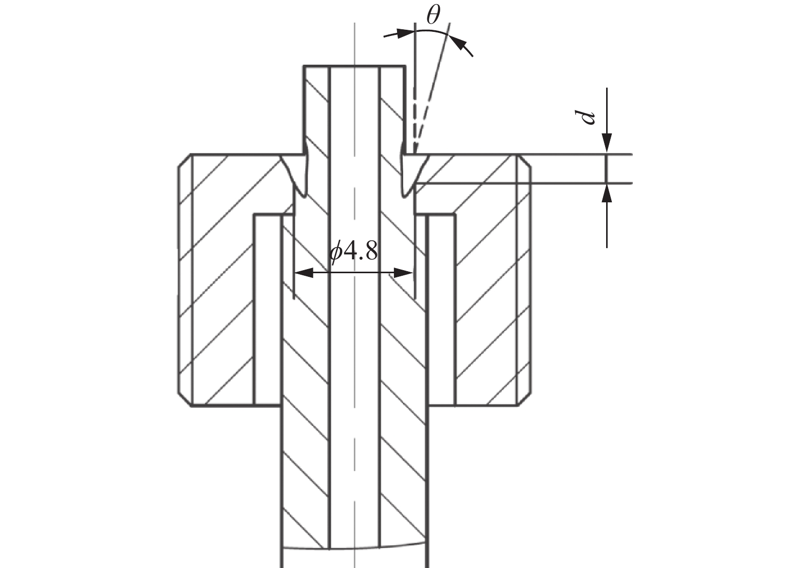
表 1 HR-2抗氢钢的化学成分(质量分数,%)Table 1. Chemical compositions of HR-2 hydrogen resistant steelC Si Mn P S Ni Cr Fe ≤0.040 ≤1.00 8.00 ~ 10.00 ≤0.025 ≤0.015 5.50 ~ 8.00 19.00 ~ 21.50 余量 试验使用某中压电子束焊机进行焊接,试件分为A,B两组,每组件数相同且标记自然顺序号,并对A,B两组相同编号的试件采用相同的焊接工艺参数,A组用来测量焊缝有效熔深,B组用来测量接头抗剪承载力. A组试件采用线切割将其截断,保留焊缝部位,截断后采用慢走丝技术将零件按截面十字切割4份,其中一份保证完整的1/4,并留有一定磨量. 焊缝截面经过打磨、抛光、草酸腐蚀,采用超景深三维显微系统观察焊缝形貌,如图1所示,测量焊缝有效熔深(图2). B组试件采用GNT100型万能试验机测量其接头抗剪承载力.
![]() 图 1 HR-2抗氢钢电子束焊接部分接头形貌Figure 1. Morphology of the electron beam welded joints of some HR-2 hydrogen resistant steel. (a) specimen 7; (b) specimen 21; (c) specimen 22; (d) specimen 25; (e) specimen 6 ; (f) specimen 14; (g) specimen 26; (h) specimen 29
图 1 HR-2抗氢钢电子束焊接部分接头形貌Figure 1. Morphology of the electron beam welded joints of some HR-2 hydrogen resistant steel. (a) specimen 7; (b) specimen 21; (c) specimen 22; (d) specimen 25; (e) specimen 6 ; (f) specimen 14; (g) specimen 26; (h) specimen 29![]() 图 2 电子束插接焊接头结构示意图(mm)Figure 2. Schematic diagram of the electron beam butt welding joint structure
图 2 电子束插接焊接头结构示意图(mm)Figure 2. Schematic diagram of the electron beam butt welding joint structure2. 数据处理方法
2.1 因素水平设计
针对某种具体产品电子束焊接生产过程中加速电压、工作距离通常保持不变,因此选取聚焦电流、焊接速度、束流和倾斜角度4个参数作为变量因素,以有效熔深和接头抗剪承载力为响应值,在焊接过程中其它参数如加速电压、束振荡等保持恒定. 焊接工艺参数的取值范围决定了所建模型的合理性、实用性和预测结果的置信度. 为保证焊缝表面无裂纹、咬边、焊瘤、气孔等焊缝成形质量缺陷及焊缝有效深度内无裂纹、未熔合、夹渣、气孔密集区(按照GB/T 22085.1—2008《电子束及激光焊接接头缺欠质量分级指南 第1部分:钢》中的B级)等缺陷,首先进行了前述4个参数的单因素焊接工艺试验,通过金相横截面分析确定了聚焦电流、焊接速度、束流和倾斜角度4个参数的取值范围,制定了4因素3水平的BBD试验方案完成HR-2抗氢不锈钢的电子束焊,其真实值与编码值如表2所示. 试验方案及响应值如表3所示.
表 2 工艺参数水平编码及真实值表Table 2. Process parameter level coding and true value table水平 聚焦电流
If /A焊接速度
v/(mm·s−1)束流
Ib /mA倾斜角度
θ/(°)1 2.49 11.40 8.65 15 0 2.46 10.00 8.20 11 −1 2.43 8.60 7.75 7 表 3 试验方案及相对应的响应值Table 3. Test scheme and corresponding response value试验序号 聚焦电流If /A 焊接速度v/(mm∙s−1) 束流Ib/mA 倾斜角度θ/(°) 有效熔深d/μm 抗剪承载力F/kN 1 2.49 10.00 8.20 15 360.07 3.856 2 2.43 10.00 8.65 11 1 997.30 16 137 3 2.46 10.00 8.20 11 1 397.18 13.037 4 2.43 10.00 7.75 11 2 117.32 16.352 5 2.43 10.00 8.20 7 2 252.73 16.779 6 2.46 10.00 8.65 15 830.92 8.938 7 2.46 10.00 8.20 11 1 275.58 12.330 8 2.46 11.40 8.20 7 1 840.34 15.907 9 2.46 10.00 7.75 7 1 717.24 16. 096 10 2.46 10.00 8.20 11 1 357.18 13.725 11 2.46 8.60 8.65 11 1 175.61 13.681 12 2.46 11.40 8.20 15 815.54 8.120 13 2.46 10.00 8.65 7 1 975.75 15.935 14 2.49 10.00 8.65 11 787.84 8.388 15 2.49 10.00 7.75 11 575.49 6.710 16 2.49 8.60 8.20 11 775.53 7.844 17 2.43 10.00 8.20 15 1 369.49 13.696 18 2.46 10.00 8.20 11 1 375.64 13.265 19 2.43 11.40 8.20 11 1 796.56 14.908 20 2.46 10.00 8.20 11 1 320.56 13.018 21 2.46 8.60 7.75 11 1 427.96 14.690 22 2.43 8.60 8.20 11 2 203.49 16.368 23 2.49 11.40 8.20 11 827.85 7.564 24 2.46 8.60 8.20 7 2 172.71 16.383 25 2.46 8.60 8.20 15 787.84 8.046 26 2.46 10.00 7.75 15 744.76 7.013 27 2.46 11.40 8.65 11 1 461.81 12.204 28 2.49 10.00 8.20 7 1 089.44 11.404 29 2.46 11.40 7.75 11 1 311.02 11.557 2.2 建立回归模型
以有效熔深和接头抗剪承载力作为响应指标,通过Design-Expert软件对聚焦电流、焊接速度、束流和倾斜角度4个自变量,以及有效熔深和接头抗剪承载力因变量进行二阶模型拟合,实现自变量的优化和响应指标的预测[7-8]. 若有k个独立变量,所有独立变量均连续可测、可调,则响应函数为
$$ Y=\stackrel{·}{{\beta }_{0}} + {\displaystyle \sum _{i=1}^{k}{\stackrel{·}{\beta }}_{i}{x}_{i}} + {\displaystyle \sum _{i=1}^{k}{\stackrel{·}{\beta }}_{ii}{x}_{i}^{2}} + {\displaystyle \sum _{i=1}^{k}{\displaystyle \sum _{j=1}^{k}{\stackrel{·}{\beta }}_{ij}{x}_{i}{y}_{j}}} + \varepsilon $$ (1) 式中:Y为预测响应值;xi为自变量;
$ \stackrel{·}{{\beta }_{0}} $ ,$ \stackrel{·}{{\beta }_{i}} $ ,$ \stackrel{·}{{\beta }_{ii}} $ ,$ \stackrel{·}{{\beta }_{ij}} $ 为回归系数;$ \varepsilon $ 为噪音或误差项.3. 结果与分析
3.1 多元非线性回归模型
有效熔深采用立方模型,其模型的方差分析结果如表4所示. 模型F值为60.48,表明模型显著,F值只有0.01%的可能性会因为噪声而变大,模型Prob > F值小于0.01%,意味着该模型显著,R2 =99.55% (R2越接近1,越显著). 对失拟项检验来说,如果失拟项Prob > F值大于0.05,说明所得模型与实际拟合中非正常误差所占比例小,即失拟项不显著,回归模型拟合较好. 从表4可以看出,模型失拟项的Prob > F值为0.0650高于0.05,说明模型失拟不显著,能正确反映有效熔深由聚焦电流、焊接速度、束流和倾斜角度之间的关系,回归模型可以较好地对结果进行预测. 由表4可知,聚焦电流、倾斜角度对有效熔深的影响最为显著. 最终的数学模型为
表 4 有效熔深模型方差分析Table 4. ANOVA for effective weld penetration reduced cubic model项目 平方和SS/105 自由度f 均放值MS /105 F值 Prob>F值 模型 80.22 22 3.646 60.48 < 0.000 1 If 11.80 1 11.80 195.74 < 0.000 1 θ 11.21 1 11.21 185.88 < 0.000 1 vIf 0.527 276 4 1 0.527 276 4 8.75 0.025 4 vIb 0.406 304 6 1 0.406 304 6 6.74 0.040 9 IfIb2 0.418 443 5 1 0.418 443 5 6.94 0.038 8 残差 0.361 760 2 6 0.060 293 4 失拟项 0.269 499 2 2 0.134 749 6 5.84 0.065 0 绝对误差 0.092 261 0 4 0.023 065 3 总离差 80.58 28 $$ \begin{split} & d = 345.23 - 543.18{I_{\rm{f}}} - 529.33\theta + 114.81v{I_{\rm{f}}} + \\&\qquad 91.83v{I_{\rm{b}}} - 120.07{I_{\rm{f}}}I_{\rm{b}}^2 \end{split} $$ (2) F采用平方模型,方差分析如表5所示,F值检验、R2检验、失拟项检验均表明模型显著. 聚焦电流If、焊接速度v和倾斜角度θ对有效熔深的影响最为显著。最终的数学模型为
表 5 接头抗剪承载力模型方差分析Table 5. ANOVA for the shear capacity of welded joins reduced quadratic model项目 平方和SS /107 自由度f 均方值MS /106 F值 Prob > F值 模型 37.13 14 26.52 36.23 < 0.000 1 If 19.58 1 195.8 267.50 < 0.000 1 v 0.379 9 1 3.799 5.19 0.038 9 θ 15.29 1 152.9 208.88 < 0.000 1 θIf 0.498 4 1 4.984 6.81 0.020 6 If2 0.729 9 1 7.299 9.97 0.007 0 θ2 0.404 7 1 4.047 5.53 0.033 9 残差 1.025 14 0.732 0 失拟项 0.923 0 10 0.923 0 3.63 0.113 0 绝对误差 0.101 8 4 0.254 6 总离差 38.15 28 $$\begin{split} & Y = 13\;075.00 - 4\;039.50{I_{\rm{f}}} - 562.67v - 3\;569.58\theta - \\& \qquad 1\;116.25\theta {I_{\rm{f}}} - 1\;060.75I_{\rm{f}}^2 - 789.88{\theta ^2} \end{split} $$ (3) 3.2 响应面法分析
3.2.1 有效熔深的响应面法分析
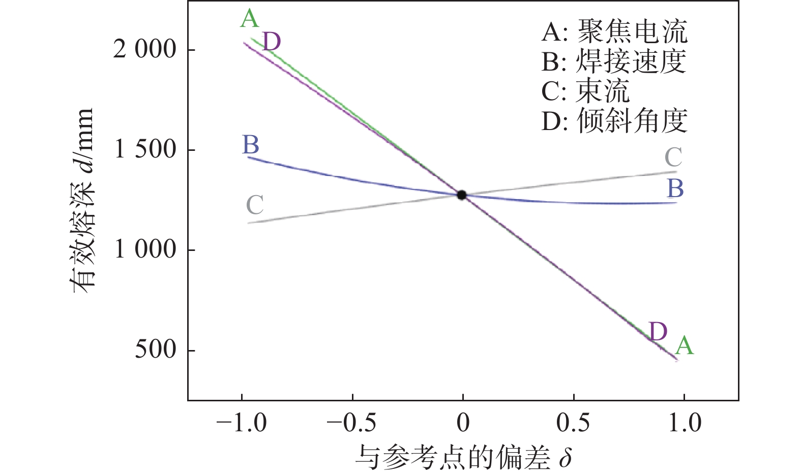
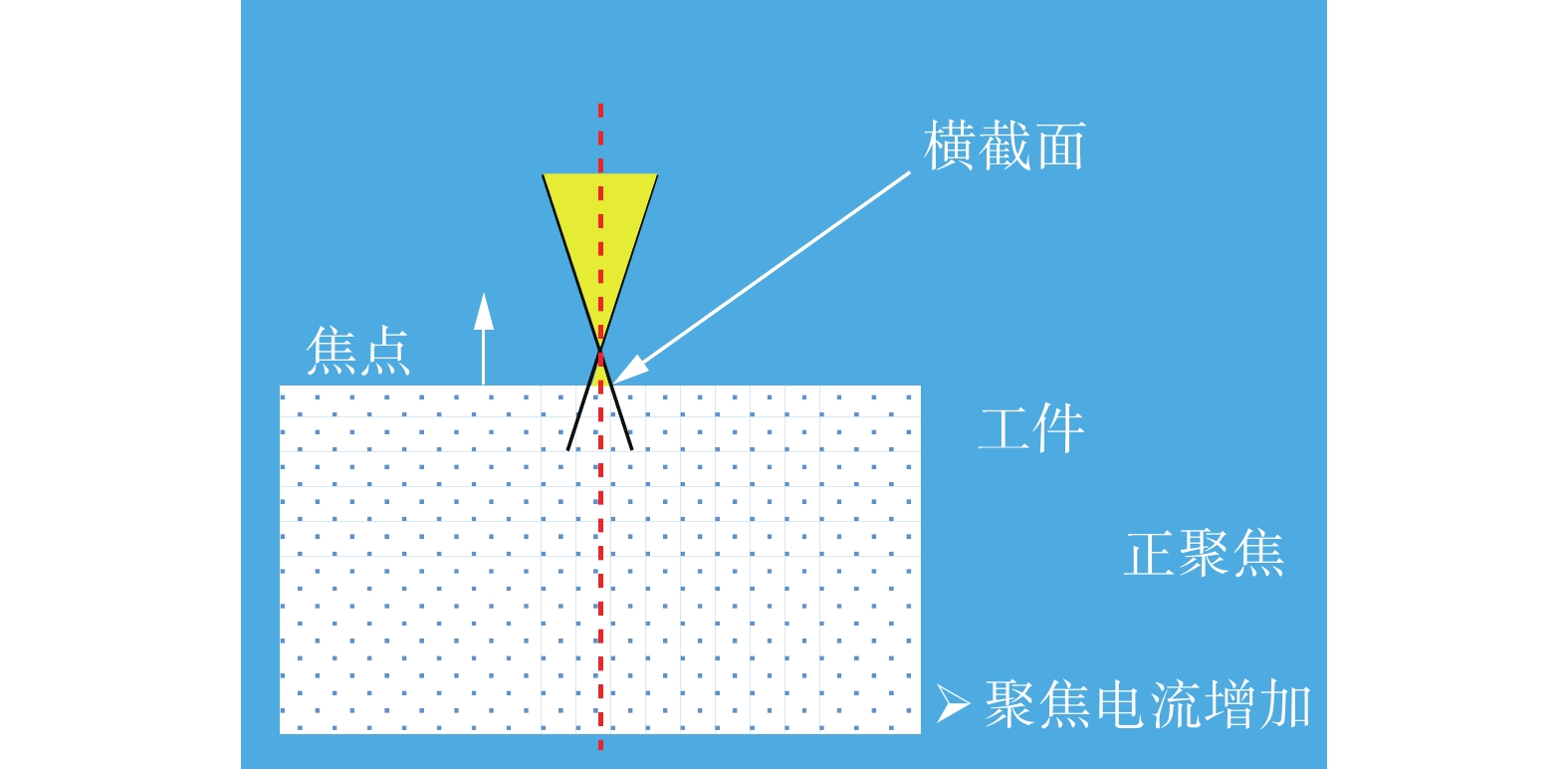
图3为各工艺参数对有效熔深的影响. 从图3可以看出,聚焦电流和倾斜角度对有效熔深的影响最为显著,并且两者对有效熔深的影响程度和方向基本一致;其次是焊接速度,有效熔深随聚焦电流或倾斜角度的增大而迅速减小,随焊接速度的增大而缓慢减小,随束流的增大而缓慢增大. 增大聚焦电流或者倾斜角度,均会使有效熔深迅速减小,原因是增加聚焦电流使磁聚焦作用增强,电子束流焦点上移(图4),到达工件表面的束流截面积增大,能量密度减小,穿透能力减弱,有效熔深减小,而增大倾斜角度将导致接头轴线与连接面之间角度增大,从而削弱有效熔深.
![]() 图 4 聚焦电流与电子束焦点位置关系示意图Figure 4. Schematic diagram of the relationship between focusing current and electron beam focal position
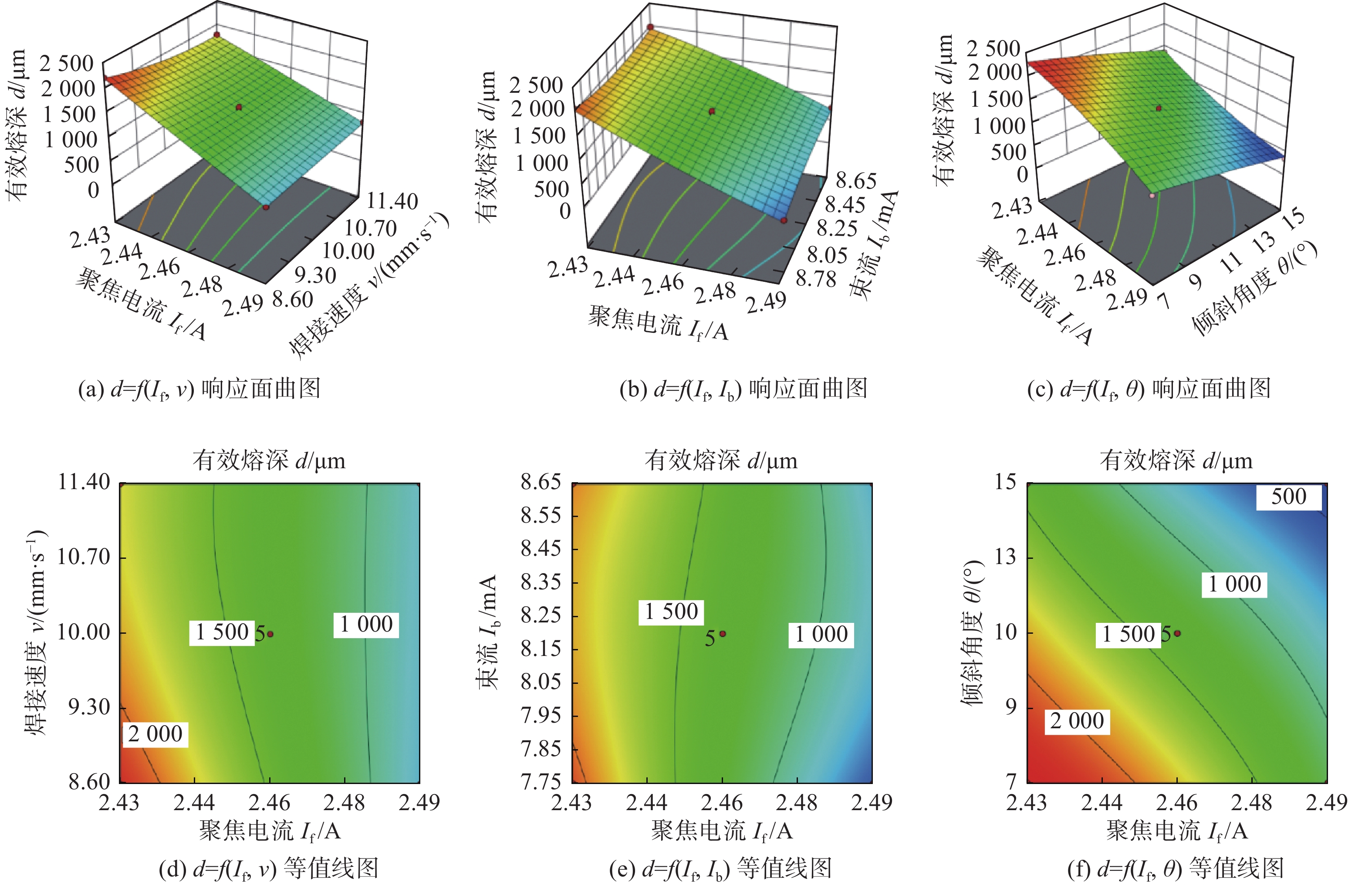
图 4 聚焦电流与电子束焦点位置关系示意图Figure 4. Schematic diagram of the relationship between focusing current and electron beam focal position图5为有效熔深的响应面曲图和等值线图. 图5a和图5d为束流8.2 mA,倾斜角度11º时,聚焦电流和焊接速度对有效熔深的交互影响. 当聚焦电流小于2.46 A、有效熔深大于1 500 μm,聚焦电流大于2.48 A时,随着焊接速度由8.60 mm/s增加到11.40 mm/s,有效熔深变化幅度不大. 图5b和图5e为焊接速度10.00 mm/s、倾斜角度11º时,束流和聚焦电流对有效熔深的交互影响. 当束流在7.75 ~ 8.65 mA时,减小聚焦电流有助于增大有效熔深.图5c和图5f为束流8.20 mA,焊接速度10.00 mm/s时,聚焦电流和倾斜角度对有效熔深的交互作用. 由等值线图可以看出,不同的参数组合可以取得相同的有效熔深,且可以根据等值线区域优化参数组合. 当聚焦电流为2.46 A、倾斜角度由7º增加到15º时,有效熔深由2000 μm减小至500 μm.
![]() 图 5 有效熔深的响应面曲图和等值线图Figure 5. Response surface 3D graph and contour graph of effective penetration. (a) d = f ( If, v) response surface 3D graph; (b) d = f (If, Ib) response surface 3D graph; (c) d = f ( If, θ ) response surface 3D graph; (d) d = f ( If, v ) contour graph; (e) d = f ( If, Ib) contour graph; (f) d = f ( If, θ ) contour graph
图 5 有效熔深的响应面曲图和等值线图Figure 5. Response surface 3D graph and contour graph of effective penetration. (a) d = f ( If, v) response surface 3D graph; (b) d = f (If, Ib) response surface 3D graph; (c) d = f ( If, θ ) response surface 3D graph; (d) d = f ( If, v ) contour graph; (e) d = f ( If, Ib) contour graph; (f) d = f ( If, θ ) contour graph3.2.2 接头抗剪承载力的响应面法分析
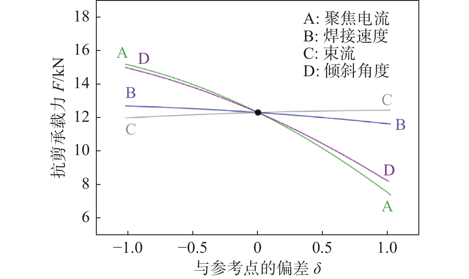
图6为各工艺参数对接头抗剪承载力的影响,可以看出,聚焦电流和倾斜角度对接头抗剪承载力具有显著影响,而焊接速度和束流对接头抗剪承载力影响不显著. 接头抗剪承载力随着聚焦电流或倾斜角度的增大而减小. 显然,小的聚焦电流或倾斜角度可使有效熔深增加,从而提高接头抗剪承载力;但小的聚焦电流会导致电子束焊缝窄而深,形成“钉尖”缺陷,小的倾斜角度可能会烧蚀零件. 而另一方面,选用大聚焦电流、大倾斜角度,由于作用在工件表面上的电子束能量密度低、接头轴线与连接面之间角度增大而使有效熔深减小,从而降低接头抗剪承载力. 因此无论是小聚焦电流小倾斜角度还是大聚焦电流大倾斜角度均不利于获得高抗剪承载力的接头.
![]() 图 6 各交互作用对接头抗剪承载力的影响Figure 6. Effect of each interaction on the shear capacity of the joints
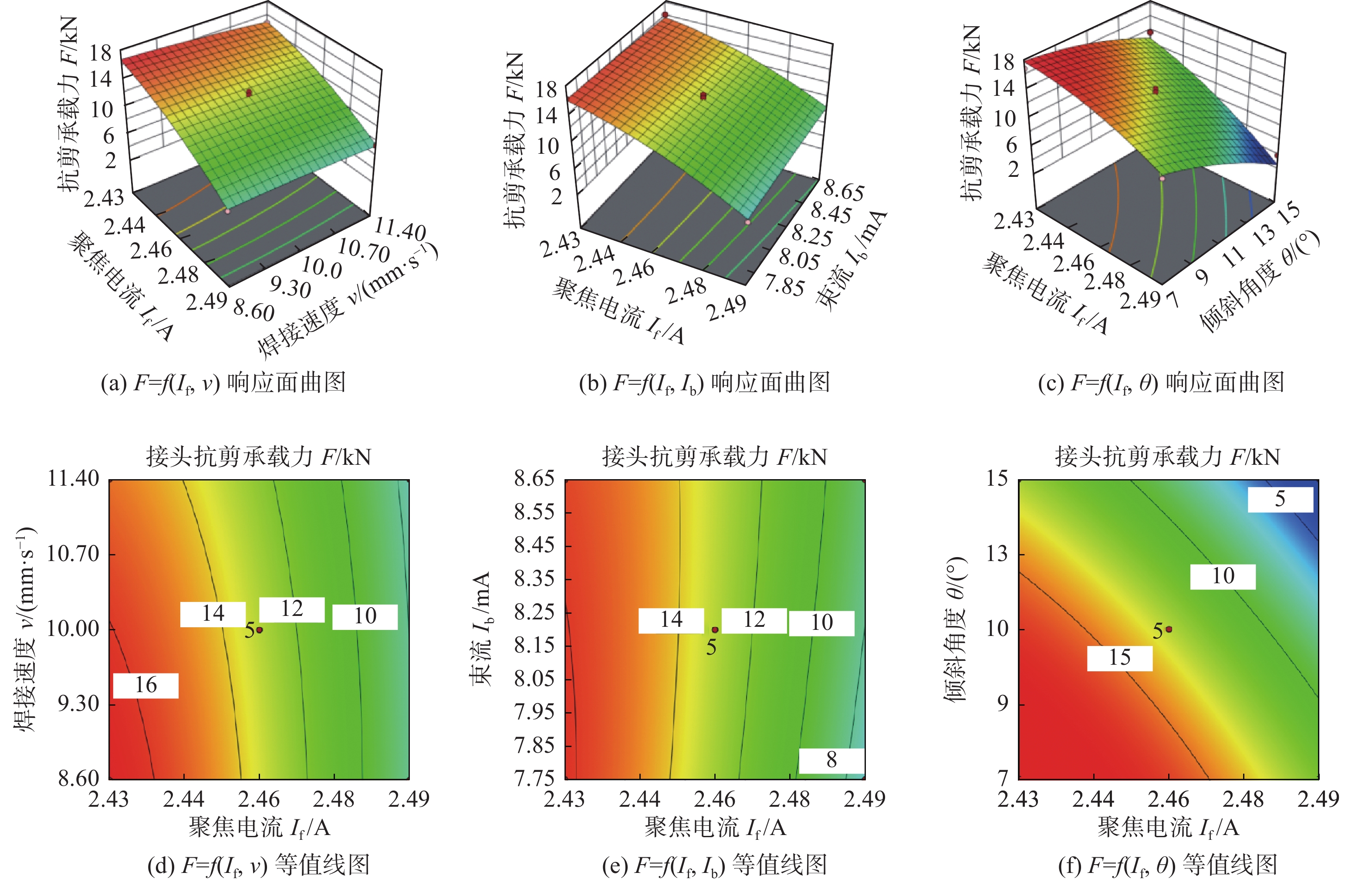
图 6 各交互作用对接头抗剪承载力的影响Figure 6. Effect of each interaction on the shear capacity of the joints图7为接头抗剪承载力的响应面曲图和等值线图. 图7a和图7d为束流8.20 mA、倾斜角度11º时,聚焦电流和焊接速度对接头抗剪承载力的交互影响. 当聚焦电流小于2.46 A,接头抗剪承载力大于14 kN,聚焦电流大于2.48 A时,接头抗剪承载力小于10 kN. 图7b和图7e为焊接速度10.00 mm/s、倾斜角度11º 时,束流和聚焦电流对接头抗剪承载力的交互影响. 当束流在7.75 ~ 8.65 mA时,减小聚焦电流有助于增大接头抗剪承载力. 图7c和图7f为束流8.20 mA、焊接速度10.00 mm/s时,聚焦电流和倾斜角度对接头抗剪承载力的交互作用. 由图7f可以看出,当聚焦电流为2.46 A、倾斜角度由7º 增加到15º 时,接头抗剪承载力由15 kN逐渐减小到10 kN.
![]() 图 7 接头抗剪承载力的响应面曲图和等值线图Figure 7. Response surface 3D graph and contour graph of of shear capacity of joint. (a) F = f (If, v) response surface 3D graph; (b) F = f (If, Ib) response surface 3D graph; (c) F = f ( If, θ ) response surface 3D graph; (d) F = f ( If, v ) contour graph; (e) F = f ( If, Ib) contour graph; (f) F = f ( If, θ) contour graphe
图 7 接头抗剪承载力的响应面曲图和等值线图Figure 7. Response surface 3D graph and contour graph of of shear capacity of joint. (a) F = f (If, v) response surface 3D graph; (b) F = f (If, Ib) response surface 3D graph; (c) F = f ( If, θ ) response surface 3D graph; (d) F = f ( If, v ) contour graph; (e) F = f ( If, Ib) contour graph; (f) F = f ( If, θ) contour graphe4. 试验验证
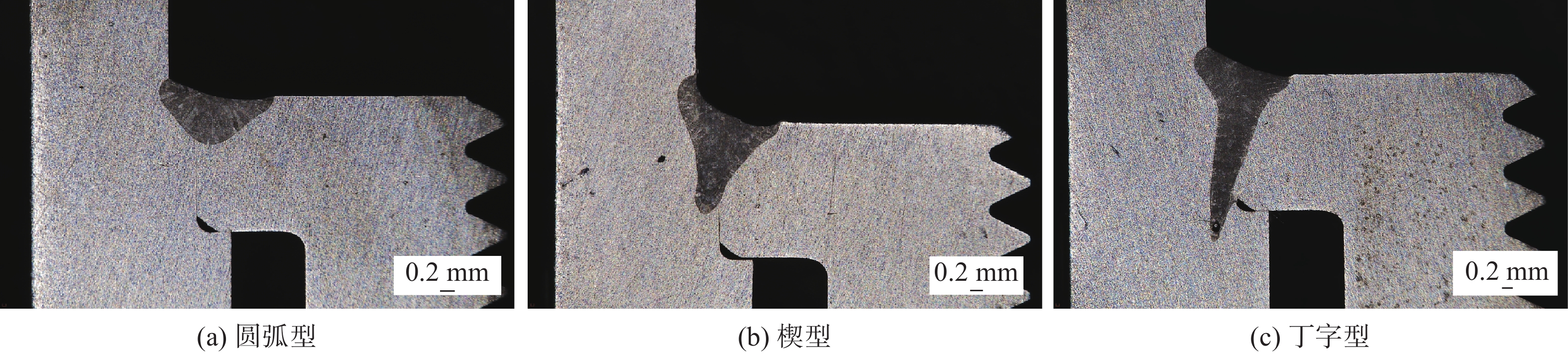
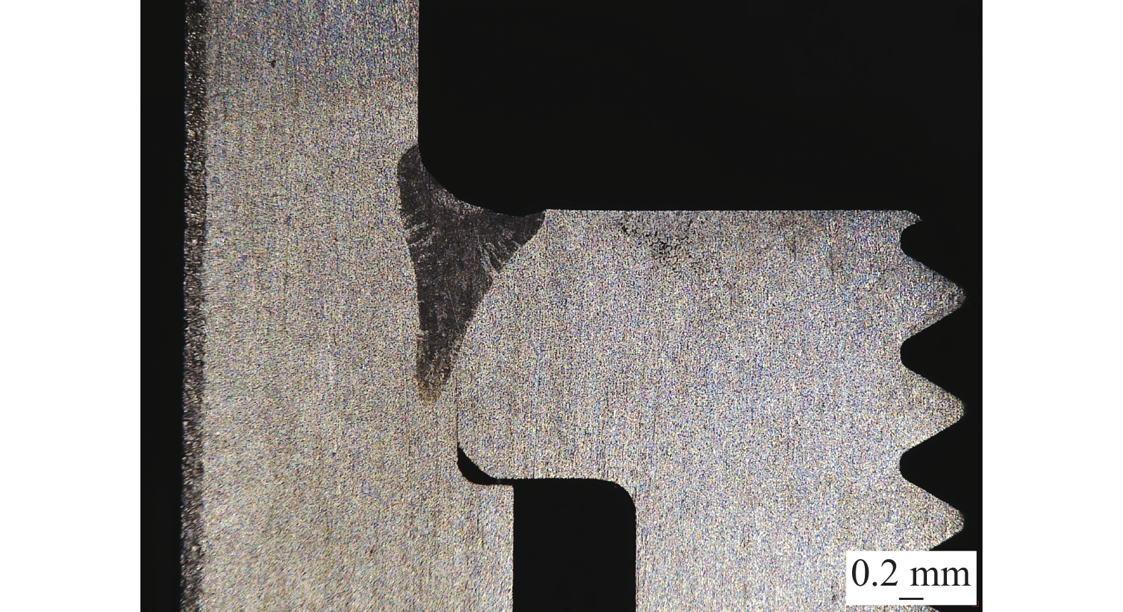
根据建立的有效熔深和接头抗剪承载力的统计方程,得出最优的焊接工艺参数组合,最终获得理想的响应. 在小尺寸插接焊中,最重要的是保证有效熔深达到规定深度且具有一定的工艺健壮性,即工艺参数保证有效熔深满足要求的同时有较强的鲁棒性. 此外,需控制焊接热输入防止焊接变形以及避免根部出现“钉尖”缺陷. 在焊接工件时,因为工件本身的加工误差、装夹、对中和找正情况以及操作者通过监控系统对工件的判断差异,会造成电子束流并不是严格在对接接缝处入射,而是有部分偏移,因此焊缝形貌不宜过窄[9-10]. 表2所选的3水平4因素参数组合下,电子束焊缝形貌主要分为圆弧型、楔型和丁字型(图8). 从图8分析得出,圆弧型焊缝的工艺健壮性最好,即电子束流出现偏移,有效熔深的波动也不显著,但其有效熔深太小,焊缝承载能力较差;而丁字型焊缝的有效熔深最大,但因其焊缝“窄而深”,并且根部产生了“钉尖”缺陷,电子束流稍有偏移,有效熔深出现明显波动,工艺健壮性较差;因此楔型焊缝既具有一定的有效熔深又具有良好的工艺健壮性,是工艺优化的目标. 运用Design Expert软件在保证聚焦电流介于2.45 ~ 2.47 A之间的条件下将目标定位于获得楔型焊缝、有效熔深介于1 300 ~ 1 500 μm,获得最优工艺参数组合.
![]() 图 8 焊缝截面形貌分类Figure 8. Classification of the cross-sectional morphology of the weld. (a) arc type; (b) wedge type; (c) T-shaped type
图 8 焊缝截面形貌分类Figure 8. Classification of the cross-sectional morphology of the weld. (a) arc type; (b) wedge type; (c) T-shaped type对统计方程分析结果进行验证,在推荐的焊接工艺参数组合下进行焊接,试验结果如图9和表6所示. 由此可见,试验值和预测值十分接近,准确性达97%以上,说明所建立的统计方程可以对插接焊电子束焊接的有效熔深进行预测.
表 6 响应面法分析优化验证结果Table 6. Optimization and verification results of response surface analysis method类别 聚焦电流If /A 焊接速度v/(mm∙s−1) 束流Ib /mA 倾斜角度θ/(°) 有效熔深d/μm 接头抗剪承载力F/kN 试验值 2.46 10.00 8.20 11 1 347.82 13.525 预测值 2.463 10.21 8.12 11.26 1 363.63 13.881 相对误差e(%) 0.12 2.1 −0.98 2.36 1.17 2.63 5. 结论
(1)利用响应面法建立了不同聚焦电流、焊接速度、束流和倾斜角度下HR-2抗氢钢电子束插接焊有效熔深和接头抗剪承载力统计模型. 经方差分析,有效熔深的模型F值为60.48,接头抗剪承载力的模型F值为36.23,模型Prob > F值均小于0.01%意味着该模型显著,验证模型有效熔深预测值比实测值高1.17%,接头抗剪承载力预测值比实测值高2.63%,证明所建模型可用于焊接工艺参数优化.
(2)经分析可知,聚焦电流和倾斜角度对焊缝的有效熔深、接头抗剪承载力影响最为显著且为负相关,束流和焊接速度对有效熔深和接头抗剪承载力的影响不显著.
(3)通过焊缝形貌和有效熔深两项指标,对工艺参数进行了优化,结果表明,试验值和预测值十分接近,准确性达97%以上,经优化可以有效控制焊缝形貌和有效熔深.
-
![]()
图 1 HR-2抗氢钢电子束焊接部分接头形貌
Figure 1. Morphology of the electron beam welded joints of some HR-2 hydrogen resistant steel. (a) specimen 7; (b) specimen 21; (c) specimen 22; (d) specimen 25; (e) specimen 6 ; (f) specimen 14; (g) specimen 26; (h) specimen 29
![]()
图 2 电子束插接焊接头结构示意图(mm)
Figure 2. Schematic diagram of the electron beam butt welding joint structure
![]()
图 4 聚焦电流与电子束焦点位置关系示意图
Figure 4. Schematic diagram of the relationship between focusing current and electron beam focal position
![]()
图 5 有效熔深的响应面曲图和等值线图
Figure 5. Response surface 3D graph and contour graph of effective penetration. (a) d = f ( If, v) response surface 3D graph; (b) d = f (If, Ib) response surface 3D graph; (c) d = f ( If, θ ) response surface 3D graph; (d) d = f ( If, v ) contour graph; (e) d = f ( If, Ib) contour graph; (f) d = f ( If, θ ) contour graph
![]()
图 6 各交互作用对接头抗剪承载力的影响
Figure 6. Effect of each interaction on the shear capacity of the joints
![]()
图 7 接头抗剪承载力的响应面曲图和等值线图
Figure 7. Response surface 3D graph and contour graph of of shear capacity of joint. (a) F = f (If, v) response surface 3D graph; (b) F = f (If, Ib) response surface 3D graph; (c) F = f ( If, θ ) response surface 3D graph; (d) F = f ( If, v ) contour graph; (e) F = f ( If, Ib) contour graph; (f) F = f ( If, θ) contour graphe
![]()
图 8 焊缝截面形貌分类
Figure 8. Classification of the cross-sectional morphology of the weld. (a) arc type; (b) wedge type; (c) T-shaped type
表 1 HR-2抗氢钢的化学成分(质量分数,%)
Table 1 Chemical compositions of HR-2 hydrogen resistant steel
C Si Mn P S Ni Cr Fe ≤0.040 ≤1.00 8.00 ~ 10.00 ≤0.025 ≤0.015 5.50 ~ 8.00 19.00 ~ 21.50 余量  下载: 导出CSV
表 2 工艺参数水平编码及真实值表
Table 2 Process parameter level coding and true value table
水平 聚焦电流
If /A焊接速度
v/(mm·s−1)束流
Ib /mA倾斜角度
θ/(°)1 2.49 11.40 8.65 15 0 2.46 10.00 8.20 11 −1 2.43 8.60 7.75 7
下载: 导出CSV
表 3 试验方案及相对应的响应值
Table 3 Test scheme and corresponding response value
试验序号 聚焦电流If /A 焊接速度v/(mm∙s−1) 束流Ib/mA 倾斜角度θ/(°) 有效熔深d/μm 抗剪承载力F/kN 1 2.49 10.00 8.20 15 360.07 3.856 2 2.43 10.00 8.65 11 1 997.30 16 137 3 2.46 10.00 8.20 11 1 397.18 13.037 4 2.43 10.00 7.75 11 2 117.32 16.352 5 2.43 10.00 8.20 7 2 252.73 16.779 6 2.46 10.00 8.65 15 830.92 8.938 7 2.46 10.00 8.20 11 1 275.58 12.330 8 2.46 11.40 8.20 7 1 840.34 15.907 9 2.46 10.00 7.75 7 1 717.24 16. 096 10 2.46 10.00 8.20 11 1 357.18 13.725 11 2.46 8.60 8.65 11 1 175.61 13.681 12 2.46 11.40 8.20 15 815.54 8.120 13 2.46 10.00 8.65 7 1 975.75 15.935 14 2.49 10.00 8.65 11 787.84 8.388 15 2.49 10.00 7.75 11 575.49 6.710 16 2.49 8.60 8.20 11 775.53 7.844 17 2.43 10.00 8.20 15 1 369.49 13.696 18 2.46 10.00 8.20 11 1 375.64 13.265 19 2.43 11.40 8.20 11 1 796.56 14.908 20 2.46 10.00 8.20 11 1 320.56 13.018 21 2.46 8.60 7.75 11 1 427.96 14.690 22 2.43 8.60 8.20 11 2 203.49 16.368 23 2.49 11.40 8.20 11 827.85 7.564 24 2.46 8.60 8.20 7 2 172.71 16.383 25 2.46 8.60 8.20 15 787.84 8.046 26 2.46 10.00 7.75 15 744.76 7.013 27 2.46 11.40 8.65 11 1 461.81 12.204 28 2.49 10.00 8.20 7 1 089.44 11.404 29 2.46 11.40 7.75 11 1 311.02 11.557
下载: 导出CSV
表 4 有效熔深模型方差分析
Table 4 ANOVA for effective weld penetration reduced cubic model
项目 平方和SS/105 自由度f 均放值MS /105 F值 Prob>F值 模型 80.22 22 3.646 60.48 < 0.000 1 If 11.80 1 11.80 195.74 < 0.000 1 θ 11.21 1 11.21 185.88 < 0.000 1 vIf 0.527 276 4 1 0.527 276 4 8.75 0.025 4 vIb 0.406 304 6 1 0.406 304 6 6.74 0.040 9 IfIb2 0.418 443 5 1 0.418 443 5 6.94 0.038 8 残差 0.361 760 2 6 0.060 293 4 失拟项 0.269 499 2 2 0.134 749 6 5.84 0.065 0 绝对误差 0.092 261 0 4 0.023 065 3 总离差 80.58 28
下载: 导出CSV
表 5 接头抗剪承载力模型方差分析
Table 5 ANOVA for the shear capacity of welded joins reduced quadratic model
项目 平方和SS /107 自由度f 均方值MS /106 F值 Prob > F值 模型 37.13 14 26.52 36.23 < 0.000 1 If 19.58 1 195.8 267.50 < 0.000 1 v 0.379 9 1 3.799 5.19 0.038 9 θ 15.29 1 152.9 208.88 < 0.000 1 θIf 0.498 4 1 4.984 6.81 0.020 6 If2 0.729 9 1 7.299 9.97 0.007 0 θ2 0.404 7 1 4.047 5.53 0.033 9 残差 1.025 14 0.732 0 失拟项 0.923 0 10 0.923 0 3.63 0.113 0 绝对误差 0.101 8 4 0.254 6 总离差 38.15 28
下载: 导出CSV
表 6 响应面法分析优化验证结果
Table 6 Optimization and verification results of response surface analysis method
类别 聚焦电流If /A 焊接速度v/(mm∙s−1) 束流Ib /mA 倾斜角度θ/(°) 有效熔深d/μm 接头抗剪承载力F/kN 试验值 2.46 10.00 8.20 11 1 347.82 13.525 预测值 2.463 10.21 8.12 11.26 1 363.63 13.881 相对误差e(%) 0.12 2.1 −0.98 2.36 1.17 2.63
下载: 导出CSV
-
[1] 丁亚茹, 陈芙蓉, 杨帆, 等. 响应面法分析7075铝合金激光焊接参数对焊接质量的影响规律[J]. 材料导报, 2021, 35(2): 2103 − 2108. Ding Yaru, Chen Furong, Yang Fan, et al. Analyzing the influence of laser welding parameters on the welding quality of 7075 aluminum alloy by response surface methodology[J]. Materials Reports, 2021, 35(2): 2103 − 2108.
[2] Mohammadpour M, Yazdian N, Wang H P, et al. Effect of filler wire composition on performance of Al/Galvanized steel joints by twin spot laser welding-brazing method[J]. Journal of Manufacturing Processes, 2018, 31: 20 − 34.
[3] Kumar C, Das M, Paul C P, et al. Experimental investigation and metallographic characterization of fiber laser beam welding of Ti-6Al-4V alloy using response surface method[J]. Optics and Lasers in Engineering, 2017, 95: 52 − 68. doi: 10.1016/j.optlaseng.2017.03.013
[4] 王洪潇, 史春元, 王春生, 等. 基于响应面法的不锈钢车体激光焊接工艺参数优化[J]. 焊接学报, 2010, 31(10): 69 − 72. Wang Hongxiao, Shi Chunyuan, Wang Chunsheng, et al. Optimization of laser welding parameters of stainless steel vehicle body based on response surface methodology[J]. Transactions of the China Welding Institution, 2010, 31(10): 69 − 72.
[5] Zhang W W, Cong S. Process optimization and performance evaluation on laser beam welding of austenitic/martensitic dissimilar materials[J]. International Journal of Advanced Manufacturing Technology, 2017, 92: 4161 − 4168.
[6] 孔谅, 周洋, 王敏, 等. TA2薄板电弧辅助激光高速焊接的焊缝成形稳定性[J]. 机械工程学报, 2021, 57(10): 137 − 147. Kong Liang, Zhou Yang, Wang Min, et al. Robustness of weld appearance on high-speed arc-assisted laser welding process on titanium sheet[J]. Journal of Mechanical Engineering, 2021, 57(10): 137 − 147.
[7] 范文学, 陈芙蓉. 基于响应面法7A52高强铝合金FSW接头抗拉强度预测及优化[J]. 焊接学报, 2021, 42(9): 55 − 60. Fan Wenxue, Chen Furong. Prediction and optimization of tensile strength of 7A52 aluminum alloy friction stir welding joints based on response surface methodology[J]. Transactions of the China Welding Institution, 2021, 42(9): 55 − 60.
[8] Acherjee B, Misra D, Bose D, et al. Prediction of weld strength and seam width for laser transmission welding of thermoplastic using response surface methodology[J]. Optics & Laser Technology, 2009, 41(8): 956 − 967.
[9] 张明敏, 胡玥, 吴家云, 等. 电子束焊接参数对高温合金小熔深焊缝形貌的影响[J]. 热加工工艺, 2017, 46(1): 233 − 235. Zhang Mingmin, Hu Yue, Wu Jiayun, et al. Effect of electron beam welding parameters on little penetration depth weld shape of high temperature alloys[J]. Hot Working Technology, 2017, 46(1): 233 − 235.
[10] 孙家豪, 张超勇, 吴剑钊, 等. 基于神经网络的316L不锈钢激光焊焊缝形貌预测[J]. 焊接学报, 2021, 42(12): 40 − 47. Sun Jiahao, Zhang Chaoyong, Wu Jianzhao, et al. Prediction of weld profile of 316L stainless steel based on generalized regression neural network[J]. Transactions of the China Welding Institution, 2021, 42(12): 40 − 47.
-
期刊类型引用(4)
1. 陆煜,赵健,石磊,白玉,王英,曾浩林. K418B与1Cr11Ni2W2MoV电子束焊缝组织及性能分析. 兵器材料科学与工程. 2024(05): 45-51 .  百度学术
百度学术
2. 蔡平,殷雄,余明俊,漆启华,姚道金. 结合响应面和改进粒子群对厂房烟尘浓度控制. 重庆理工大学学报(自然科学). 2024(12): 224-231 . 百度学术
3. 张楷,高辉,林渊浩,邵明启. 基于RSM和NSGA-Ⅱ算法的同轴送粉氩弧熔覆工艺参数分析. 焊接学报. 2024(12): 106-116 . 本站查看
4. 解天虎. 焊接工艺在机械维修中的应用及优化措施. 造纸装备及材料. 2023(06): 116-118 . 百度学术
其他类型引用(6)


计量
- 文章访问数: 232
- HTML全文浏览量: 43
- PDF下载量: 39
- 被引次数: 10
