
A cylindrical capacitance sensor suitable for automatic arc tracking system of narrow gap weld
-
摘要: 焊缝跟踪系统是实现智能焊接的关键技术之一,针对窄间隙焊缝中焊缝实时跟踪困难等问题,文中设计了一种基于边缘电场技术的多极阵列电容传感器,并通过结合了小波滤波与非线性映射技术的电容信号处理技术,实现了该传感器对窄间隙焊缝坡口形貌的重构. 首先,建立了该传感器的数学模型,得到了多极阵列电容传感器的相关理论数值,并结合有限元仿真分析,优化了传感器结构. 随后,通过电容信号处理技术实现了对传感器电容信号的提取及优化,获得了焊枪偏移及焊缝偏差信号,完成了焊缝坡口形貌重构. 结果表明,多极阵列电容传感器应用于窄间隙焊缝跟踪系统是可行的,对窄间隙焊缝跟踪具有重要意义.Abstract: Seam tracking system is one of the key technology to realize intelligent welding. Aiming at the problems of welding seam tracking in narrow gap, such as the difficulty of real time seam tracking weld seam of sensor, a new multipole array capacitive sensor based on fringe electric field technology is designed. And the welding seam surface reconstruction is realized through the capacitive signal processing technology based on wavelet filtering and nonlinear mapping technology. Firstly, a mathematical model of multipole array capacitive sensing is established, and the capacitive sensor structure is optimized through theory calculation results and finite element simulation analysis. Subsequently,The capacitive signal of the sensor is extracted and optimized with the help of capacitance signal processing technology, the welding gun offset,and weld deviation are both obtained. The results show that the reconstructed weld surface is basically the same as the narrow gap weld in the experiment, and it is feasible for the multipole array capacitive sensor applying to narrow gap weld tracking, which is of great significance for narrow gap weld tracking.
-
0. 序言
随着工业的不断发展,焊接技术也必须不断革新,以实现产品生产自动化、智能化、柔性化. 其中,所需解决的关键问题之一就是焊缝跟踪传感技术. 在轨道交通等领域的大型构件制造通常需要采用焊接等连接技术来实现,这类构件通常采用中厚板材质,由此产生许多窄间隙焊缝[1]. 然而窄间隙焊接存在焊缝坡口狭窄、侧壁面接近垂直、传感器难以到达以及电弧和熔滴过渡稳定性差等问题[2],大大制约了中厚板窄间隙焊接自动化水平的提升. 因此,开展中厚板窄间隙焊接的焊缝跟踪传感技术具有十分重要的意义.
针对中厚板窄间隙焊缝焊接,洪波等人[3]采用磁控与电感复合式传感器实现了焊缝跟踪,该传感器对小角度斜坡跟踪效应较好,但对于跨度大的阶梯信号跟踪精度低. Yang等人[4]通过计算光路在窄间隙坡口内部传输路径,通过多层填充激光焊实现了100 mm厚不锈钢窄间隙焊缝焊接,其焊接变形小,焊缝成形良好. Liu等人[5]通过控制双丝窄间隙气体保护焊的线距与弧长修正系数获得了较好的焊缝,但是频繁的断弧会导致10 mm或20 mm窄槽侧壁欠填充等缺陷.
电容传感器为非接触式传感器,目前在距离测量领域得到了广泛应用,课题组前期也对将电容传感器应用于焊缝跟踪进行了系统研究. 2014年,采用摆动式相邻电容传感器扫描焊缝坡口采集电容值,根据不同的电容值进一步获取焊缝偏差,从而进行焊缝跟踪[6-7];2015年,针对平板对接焊接容易出现错边等问题,采用电容传感与电感相结合的方法设计了一种桥式焊缝跟踪传感器[8]. 以上研究证实了电容传感器在焊缝跟踪中具有体积小,耐高温和抗干扰能力强等优点,为解决中厚板窄间隙焊缝的跟踪问题带来了希望.
文中设计了一种多极阵列电容传感器,该传感器采用一种适用于窄间隙焊接的电容边缘电场技术. 焊接信息通过检测窄间隙焊接坡口的空间位置信息来获取,主控制器用于运算处理经过信号处理电路的焊缝偏差信息,对于产生的焊枪偏差,采用执行模块予以补偿,最终实现对于窄间隙焊缝的自动跟踪.
1. 多极阵列电容传感器设计
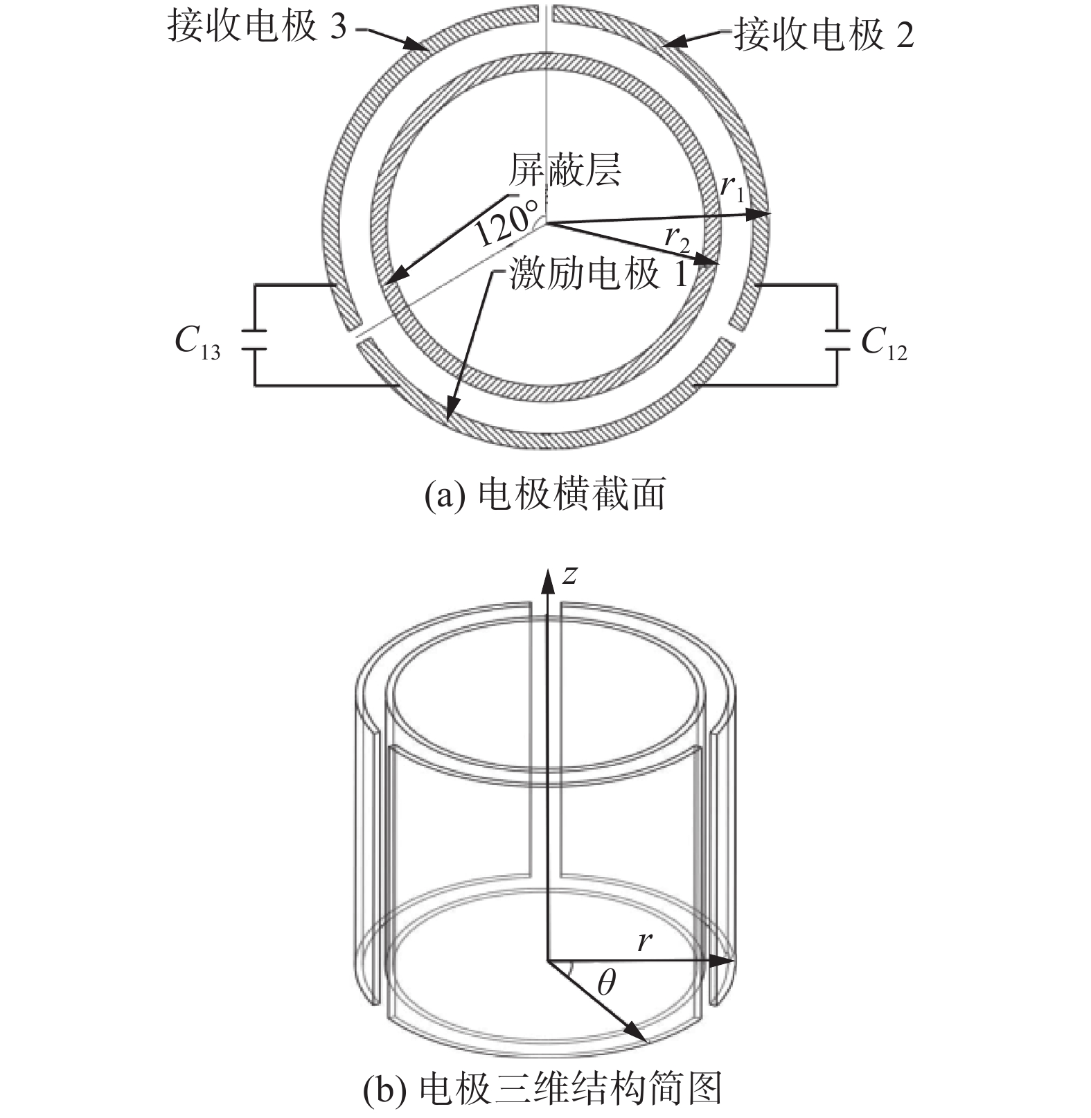
针对中厚板的窄间隙焊缝,文中提出一种多极阵列电容传感器,该传感器呈环状和平面阵列分布,由激励电极、接收电极和屏蔽电极组成. 如图1所示为多极阵列电容传感器各类参数优化后结构,屏蔽电极分布于圆柱体内表面,另外2种电极则处外侧圆柱面. 三电极中,有且只有一个激励电极,其余两个均为接收电极,其中电极厚度为2 mm,径向保护层与电容顶层保护层厚度均取1 mm.
![]() 图 1 电极结构简图Figure 1. Electrode structure diagram. (a) cross section of electrode; (b) three-dimensional structure of electrodes
图 1 电极结构简图Figure 1. Electrode structure diagram. (a) cross section of electrode; (b) three-dimensional structure of electrodes为了适应窄间隙焊缝环境,将电极与焊枪喷嘴结合,设计了焊枪喷嘴型三电极结构,如图2所示. 当进行二氧化碳或惰性气体保护焊时,由于该多极阵列电容传感器维持了焊枪的原有结构,既能确保焊接时气体的稳定流动,也能通过感应焊枪位置获取焊缝偏离信息,实现焊缝跟踪. 为保证传感器与焊枪喷嘴的配合,电容传感器内腔尺寸与普通喷嘴相同. 焊枪喷嘴座通过螺纹口与焊枪配合,螺纹口两侧接口用于输入输出信号. 传感器各层之间相互绝缘且可抗高温变形. 其中,根据不同焊接工艺焊枪喷嘴尺寸变化需求,传感器外形可灵活调整,但必须保证传感器电场分布的密集区能同时作用于焊枪和焊缝.
2. 多极阵列电容传感器模型
2.1 传感器原理
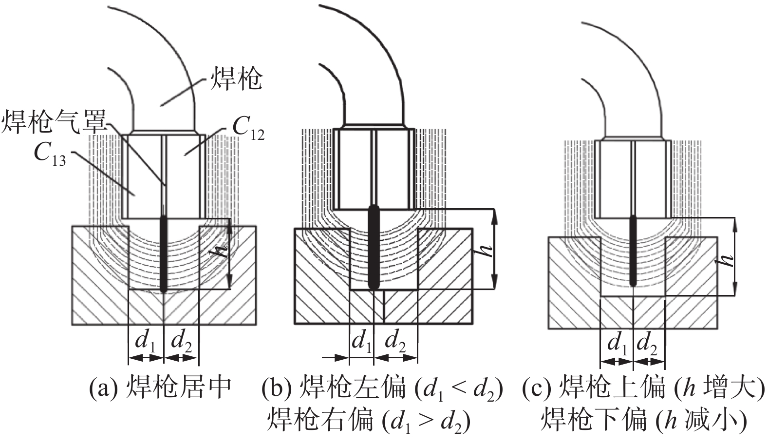
如图3所示,在针对窄间隙焊缝的焊接过程中,经电容传感器产生电场布满焊枪周围,当焊枪产生偏移时,电场也会随之发生变化,从而进一步影响电容值.
![]() 图 3 电容传感器在窄间隙焊缝中的空间位置关系Figure 3. Spatial position relationship of the capacitance sensor in the narrow gap weld. (a) welding gun in the center; (b) welding gun offset to the lefto, welding gun offset to the right; (c) welding gun offset upwards, welding gun downward offset
图 3 电容传感器在窄间隙焊缝中的空间位置关系Figure 3. Spatial position relationship of the capacitance sensor in the narrow gap weld. (a) welding gun in the center; (b) welding gun offset to the lefto, welding gun offset to the right; (c) welding gun offset upwards, welding gun downward offset对于焊缝跟踪过程,采集两组不同的信号进行分析,分别为激励电极1与接收极板2产生的电容
$C_{12}$ 激励电极1与另一接收极板3产生的电容$C_{13}$ 焊枪居中时,如图3a所示,此时$C_{12} = C_{13}$ . 如图3b所示,当焊枪右偏时,$d_1 > d_2$ 时$C_{13 } > C_{12}$ 焊枪左偏时,$d_1 < d_2$ 时$C_{13} < C_{12}$ . 如图3c所示,当焊枪高度产生变化时,$h$ 增大时,各极板电容值都随之增大;$h$ 减小时,各极板电容值则随之减小. 根据电容值大小关系可初步判断焊枪偏移方向,通过试验装置获取电容信号后,还需进一步滤波放大提取有用信息. 再进一步进行非线性映射处理后,获取焊枪偏离焊缝的空间位置信息.2.2 传感器的理论模型
对于多极阵列电容传感器内部电极结构,作出如下假设:电容传感器高度远大于其半径,电极与屏蔽层厚度极小且两者无限靠近,激励电极与接收电极间隙为无穷小.
为简化多极阵列电容传感器模型,建立如图1b所示柱坐标系. 其中,设电势函数为
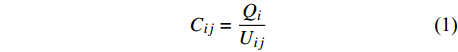
$ U\left(R,\theta ,{\textit{z}}\right) $ 于电容传感器长度远大于其半径,忽略${\textit{z}} $ 轴影响,即电容的计算公式为$$ {C_{ij}} = \dfrac{{{Q_i}}}{{{U_{ij}}}} $$ (1) 式中:
${Q_i}$ 为$i$ 上感应出的总电荷量,单位为C;${U_{ij}}$ 为板之间的电势差,单位为V. 建立二维柱坐标系,利用叠加原理,令$$ u\left(r\text{,}\theta \text{,}{\textit{z}}\right)=\omega \left(r\text{,}\theta \text{,}{\textit{z}}\right) + \nu \left(r\text{,}\theta \text{,}{\textit{z}}\right) $$ (2) 式中:
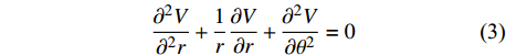
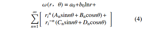
$\omega \left(r,\theta ,{\textit{z}}\right)$ 为aplace方程,根据文献[9]可知柱坐标系中的laplace方程为$$ \dfrac{{{\partial ^2}V}}{{{\partial ^2}r}} + \dfrac{1}{r}\dfrac{{\partial V}}{{\partial r}} + \dfrac{{{\partial ^2}V}}{{\partial {\theta ^2}}} = 0 $$ (3) 根据分离变量法可得laplace方程的通解为
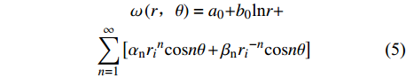
$$ \begin{split} &\qquad \omega \left(r\text{,}\theta \right)={a}_{0}{{ + b}}_{0}\text{ln}r+\\& \displaystyle \sum _{n=1}^{\infty }\left[\begin{array}{c}{r}_{i}{}^{n}\left({A}_{{\rm{n}}}\mathrm{sin}n\theta + {B}_{{\rm{n}}}\mathrm{cos}n\theta \right)+\\ {r}_{i}{}^{-n}\left({C}_{{\rm{n}}}\mathrm{sin}n\theta + {D}_{{\rm{n}}}\mathrm{cos}n\theta \right)\end{array}\right] \end{split} $$ (4) 由于该电容传感器为轴对称结构,故方程可变换为
$$ \begin{split} &\qquad \omega \left(r\text{,}\theta \right)={a}_{0}{{ + b}}_{0}\text{ln}r+\\& \displaystyle \sum _{n=1}^{\infty }\left[{\alpha }_{{\rm{n}}}{r}_{i}{}^{n}\mathrm{cos}n\theta + {\beta }_{{\rm{n}}}{r}_{i}{}^{-n}\mathrm{cos}n\theta \right] \end{split} $$ (5) 式中:
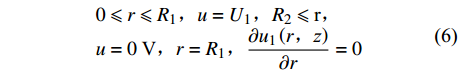
$ {a}_{0},{b}_{0},{A}_{{\rm{n}}},{B}_{{\rm{n}}},{C}_{{\rm{n}}},{D}_{{\rm{n}}} $ 为待定常数,且${\alpha }_{{\rm{n}}}= {B}_{{\rm{n}}}, {\beta }_{{\rm{n}}}={D}_{{\rm{n}}}$ .根据假设条件Dirichlet外问题及Neumann外问题求解模型,获得如图1所示的多极阵列传感器的边界条件.区域1:
$$ \begin{array}{l}0\leqslant r\leqslant {R}_{1}\text{,}u=U_1\text{,}{R}_{2}\leqslant \text{r}\text{,}\\ {u}=0\;\text{V}\text{,}r={R}_{1}\text{,}\dfrac{\partial {u}_{1}\left(r\text{,}{\textit{z}}\right)}{\partial r}=0\end{array} $$ (6) 区域2:
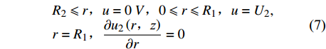
$$ \begin{array}{l}{R}_{2}\leqslant r\text{,}u=0\;V\text{,}0\leqslant r\leqslant {R}_{1}\text{,}u={U}_{2},\\ r={R}_{1}\text{,}\dfrac{\partial {u}_{2}\left(r\text{,}{\textit{z}}\right)}{\partial r}=0\end{array} $$ (7) 区域1和区域2的共同边界为
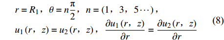
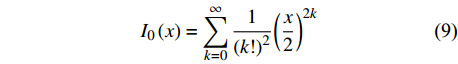
$$ \begin{array}{l}r={R}_{1}\text{,}\theta =n\dfrac{{\text{π}} }{2}\text{,}n=\left(1\text{,}3\text{,}\mathrm{5}\cdots \right)\text{,}\\ {u}_{1}\left(r\text{,}{\textit{z}}\right)= {u}_{2}\left(r\text{,}{\textit{z}}\right)\text{,} \dfrac{\partial {u}_{1}\left(r\text{,}{\textit{z}}\right)}{\partial r}=\dfrac{\partial {u}_{2}\left(r\text{,}{\textit{z}}\right)}{\partial r}\end{array} $$ (8) 同时考虑贝塞尔修正函数.
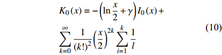
$$ {I_0}\left( x \right) = \displaystyle \sum _{k = 0}^\infty \dfrac{1}{{{{(k!)}^2}}}{\left(\dfrac{x}{2}\right)^{2k}} $$ (9) $$ \begin{gathered} {K_0}\left( x \right) = - \left( {\ln \dfrac{x}{2} + \gamma } \right){I_0}\left( x \right)+ \\ \displaystyle\sum_{k = 0}^\infty \dfrac{1}{{{{(k!)}^2}}}{\left(\dfrac{x}{2}\right)^{2k}} \displaystyle \sum _{i = 1}^k \dfrac{1}{l} \\ \end{gathered} $$ (10) 由此,求得式(5)具体表达式为
$$\begin{split} {\omega }_{1}\left(r,\theta \right)=-\dfrac{{u}_{1}\mathrm{ln}{R}_{2}}{\mathrm{ln}\dfrac{{R}_{1}}{{R}_{2}}} + \dfrac{{u}_{1}}{\mathrm{ln}\dfrac{{R}_{1}}{{R}_{2}}}g\mathrm{ln}r + \sum \limits_{n = 1}^\infty \left[ {\dfrac{{{K_1}\left( {n{\text{π}} {R_2}} \right)}}{{{I_1}\left( {n{\text{π}} {R_2}} \right)}}{I_1}\left( {n{\text{π}} {R_1}} \right) - {K_1}\left( {n{\text{π}} {R_1}} \right)} \right] \cdot {I_0}\left( {n{\text{π}} r} \right)\cos \left( {n{\text{π}} r} \right) \end{split} $$ (11) $$ \begin{split} & {\omega }_{2}\left(r\text{,}\theta \right)=-\dfrac{{u}_{2}\mathrm{ln}{R}_{2}}{\mathrm{ln}\dfrac{{R}_{1}}{{R}_{2}}} + \dfrac{{u}_{2}}{\mathrm{ln}\dfrac{{R}_{1}}{{R}_{2}}}g\mathrm{ln}r+ \displaystyle \sum _{n=1}^{\infty }\left[\dfrac{{K}_{1}\left(n{\text{π}} {R}_{2}\right)}{{I}_{1}\left(n{\text{π}} {R}_{2}\right)}{I}_{1}\left(n{\text{π}} {R}_{1}\right)-{K}_{1}\left(n{\text{π}} {R}_{1}\right)\right]\cdot {I}_{0}\left(n{\text{π}} r\right)\mathrm{cos}\left(n{\text{π}} r\right) \end{split}$$ (12) 式(2)再通过poisson方程特解法可得
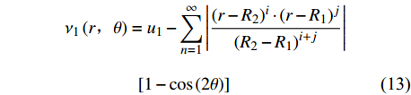
$$\begin{split} & {\nu }_{1}\left(r\text{,}\theta \right)={u}_{1}-\displaystyle \sum _{n=1}^{\infty }\left|\dfrac{{\left(r-{R}_{2}\right)}^{i}\cdot {\left(r-{R}_{1}\right)}^{j}}{{\left({R}_{2}-{R}_{1}\right)}^{i + j}}\right|\\&\qquad\qquad \left[1-\mathrm{cos}\left(2\theta \right)\right] \end{split} $$ (13) $$ \begin{split} & {\nu }_{2}\left(r\text{,}\theta \right)={u}_{2} + \displaystyle \sum _{n=1}^{\infty }\left|\dfrac{{\left(r-{R}_{2}\right)}^{i}\cdot {\left(r-{R}_{1}\right)}^{j}}{{\left({R}_{2}-{R}_{1}\right)}^{i + j}}\right|\\&\qquad\qquad \left[1-\mathrm{cos}\left(2\theta \right)\right] \end{split} $$ (14) 将式(11) ~ 式(14)叠加,得出多极阵列电容传感器电势分布为
$$\begin{split} &\qquad {\omega }_{1}\left(r\text{,}\theta \right)=-\dfrac{{u}_{1}\mathrm{ln}{R}_{2}}{\mathrm{ln}\dfrac{{R}_{1}}{{R}_{2}}} + \dfrac{{u}_{1}}{\mathrm{ln}\dfrac{{R}_{1}}{{R}_{2}}}g\mathrm{ln}r+\\& \displaystyle \sum _{n=1}^{\infty }\left[\dfrac{{K}_{1}\left(n{\text{π}} {R}_{2}\right)}{{I}_{1}\left(n{\text{π}} {R}_{2}\right)}{I}_{1}\left(n{\text{π}} {R}_{1}\right)-{K}_{1}\left(n{\text{π}} {R}_{1}\right)\right] \end{split} $$ (15) $$\begin{split} &\qquad {\omega }_{2}\left(r\text{,}\theta \right)=-\dfrac{{u}_{2}\mathrm{ln}{R}_{2}}{\mathrm{ln}\dfrac{{R}_{1}}{{R}_{2}}} + \dfrac{{u}_{2}}{\mathrm{ln}\dfrac{{R}_{1}}{{R}_{2}}}g\mathrm{ln}r+\\& \displaystyle \sum _{n=1}^{\infty }\left[\dfrac{{K}_{1}\left(n{\text{π}} {R}_{2}\right)}{{I}_{1}\left(n{\text{π}} {R}_{2}\right)}{I}_{1}\left(n{\text{π}} {R}_{1}\right)-{K}_{1}\left(n{\text{π}} {R}_{1}\right)\right] \end{split} $$ (16) 获取激励电极极板在r = R1处的总电荷量后,可得多极阵列电容传感器的电容计算式为
$$ C=\left.\frac{\varepsilon_0 \varepsilon_r}{V_0} \iint \frac{\partial u_1(r, \theta)}{\partial \theta}\right|_{r=R_1} d A=h {\text{π}} r \varepsilon_0 \varepsilon_r$$ (17) 式中:
$\varepsilon $ 为对介电常数;${R_1}$ 为电极半径;${R_2}$ 为检测物表面半径;$h$ 为圆柱电容的高度.${I_0}\left( x \right)$ 与${I_1}\left( x \right)$ 为一类与第二类的一阶的贝塞尔修正函数.由此可见当,
${R_2}$ 增大时,待测物体远离电容,电容值将会随之增大;当${R_1}$ 增大时,电容传感器的大小增大,电容值亦会增大. 该结论为电容传感器检测实际焊缝形状以及获取传感器与焊枪之间的距离数值提供了理论计算依据.2.3 传感器的灵敏度
据文献[10]显示,对于电容传感器内部结构,极板覆盖率会大大影响传感器测量灵敏度,传感器的灵敏度会随极板覆盖率减小而减小. 下面系统研究极板覆盖率分别为50%,75%,90%时电容传感器的灵敏度.
电容传感器的灵敏度计算式为
$$ \mu = \dfrac{{{C_{{\text{max}}}} - {C_{{\text{min}}}}}}{{{d_1} - {d_2}}} $$ (18) 式中:
$\mu $ 电容传感器的灵敏度;${d_1}$ 极板距离变化范围;${C_{{\text{max}}}}$ 表示在一定范围内的最大电容值;${C_{{\text{min}}}}$ 为最小电容值.结合图1,文中设计不同极板覆盖率时(由大到小)的极板距离分别为2.18,6.54,13.05 mm,结合测量出的最大最小电容值,得到极板覆盖率分别为90%,75%,50%时,电容传感器灵敏度平均值分别约为58.2,2.56,0.42 pF/m. 即极板覆盖率越高,传感器灵敏度越好,因此传感器设计时要优先极板高覆盖率的传感器.
2.4 传感器电场分布仿真优化
为进一步确认电容传感器极板覆盖率对传感器电场的影响,采用ANSYS对多极阵列相邻电容传感器进行仿真分析[11],电极电导率、相对介电常数取5.998 × 10⁷ m和1.0,磁导率
$\mu = 1$ 电势分布如图4所示. 当电容极板覆盖率为50%时(图4a),电场线仅覆盖整个传感器的40%左右;当极板覆盖率增加到75%时(图4b),仍有部分区域没有电场线穿过;当极板覆盖率为90%时(图4c),电场基本全覆盖传感器. 由此可见,径向电势下降速度随极板间跨度增加而变缓,电势分布范围变宽,垂直横截面电势分布亦然.![]() 图 4 极板覆盖率不等时水平横截面电势分布图Figure 4. Equipotential distribution map of horizontal cross-section with unequal plate coverage. (a) pole plate coverage of 50%; (b) pole plate coverage of 75%; (c) pole plate coverage of 90%
图 4 极板覆盖率不等时水平横截面电势分布图Figure 4. Equipotential distribution map of horizontal cross-section with unequal plate coverage. (a) pole plate coverage of 50%; (b) pole plate coverage of 75%; (c) pole plate coverage of 90%综合上述对电容传感器的理论以及有限元仿真分析,极板覆盖率为90%的多极阵列相邻电容传感器信号强度较强、分辨率较高、测量灵敏度与动态范围大,为最优电极间隙结构.
3. 电容传感器分析与焊缝偏移
3.1 焊缝偏差信号提取的仿真分析
图5为窄间隙焊缝模型图与坡口模型重建图,为了探索多极阵列电容传感器对窄间隙焊缝偏差信号的提取及滤波方法,建立如图5a所示的检测数值模型,同时进行有限元仿真模拟. 其中,设定焊缝最低点到传感器之间的距离为15 ~ 35 mm,求解6步;焊炬中心到所测焊缝的横向偏差距离设定为−5 ~ 5 mm,求解6步;对焊缝的空间位置求解分析,则共求解36步,获得36组电容值.
![]() 图 5 窄间隙焊缝模型与坡口模型重建Figure 5. Narrow gap weld model diagram and reconstruction of groove model variation of the lateral and longitudinal offsets. (a) narrow gap weld model diagram; (b) reconstruction diagram of groove model
图 5 窄间隙焊缝模型与坡口模型重建Figure 5. Narrow gap weld model diagram and reconstruction of groove model variation of the lateral and longitudinal offsets. (a) narrow gap weld model diagram; (b) reconstruction diagram of groove model对于仿真模拟过程,考虑到电容值
$C_{13}$ 离产生的变化值为已知关系,因此只需将任意一组仿真数据导入MATLAB进行数值处理,选取焊枪产生偏移时的$C_{12}$ 值分析,可得如图6所示电容变化曲线图,电容值随偏差距离变化而产生显著变化,即文中优化设计的多极阵列电容传感器在检测窄间隙焊缝时能够获得变化明显的电容数值.![]() 图 6 焊缝横向及纵向偏移时电容
图 6 焊缝横向及纵向偏移时电容$C_{12}$ 化曲面图Figure 6. Curve of capacitance C12 variation when the welding gun deviates horizontally and longitudinally3.2 焊枪偏移量计算
电容值与焊枪偏移量之间呈非线性比例关系,因此要将电容值进行线性拟合,得出曲线方程再采用Gaussian 二项式方程无限求解拟合曲线. 如图7所示电容值
$C_{12}$ 偏差下非线性映射点拟合曲线图, 电容值与横向偏移关系式为$e$ 数关系$C \propto k{e^x}$ 性均方差为0.037 ~ 0.012,非线性误差范围为13.56% ~18.98%. 经过非线性映射拟合后,所选取的电容横向偏差信号曲线线性度明显提高,达到0.97% ~ 0.99%,满足焊缝跟踪精度要求.![]() 图 7 电容值横向偏差下非线性映射点拟合曲线图Figure 7. Nonlinear mapping point fitting curve of capacitance value under lateral deviation
图 7 电容值横向偏差下非线性映射点拟合曲线图Figure 7. Nonlinear mapping point fitting curve of capacitance value under lateral deviation对于不同的横向偏移,同一高度的值基本不变,再经过线性变换,可得
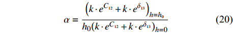
$$ h = \alpha \cdot \left( {k \cdot {e^{{C_{12}}}} + k \cdot {e^{{\delta _{12}}}}} \right) $$ (19) 式中:δ表示电容
$C_{12}$ 的相对系数;$k$ 为数据缩小倍数,取$k = 50\;000$ ,$\alpha $ 为$$ \alpha = \dfrac{{{{\left( {k \cdot {e^{{C_{12}}}} + k \cdot {e^{{\delta _{13}}}}} \right)}_{h = {h_0}}}}}{{{h_0}{{\left( {k \cdot {e^{{C_{12}}}} + k \cdot {e^{{\delta _{13}}}}} \right)}_{h = 0}}}} $$ (20) 通过计算
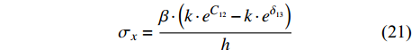
$\alpha $ 可以得出焊枪当前高度值.为进一步获取焊枪横向偏移距离值,与高低偏移距离提取方式相似,设定在焊枪纵向偏移过程中电容值改变的影响去除, 随后进行式(20)的处理,获得左右偏移值大小与高度偏移值的关系式,即
$$ \sigma_x = \dfrac{{\beta \cdot \left( {k \cdot {e^{{C_{12}}}} - k \cdot {e^{{\delta _{13}}}}} \right)}}{h} $$ (21) 式中:
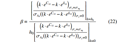
$\sigma_x$ 为横向偏移量,负数表示焊枪相对于焊缝中心左偏,正数则表示相对于焊缝中心右偏. 系数$\beta $ 为$$ \beta = \dfrac{{{{\left[ {\dfrac{{{{\left( {k \cdot {e^{{C_{12}}}} - k \cdot {e^{{\delta _{13}}}}} \right)}_{\sigma_x = {\sigma_{x_0}}}}}}{{{\sigma_{x_0}}{{\left( {\left( {k \cdot {e^{{C_{12}}}} - k \cdot {e^{{\delta _{13}}}}} \right)} \right)}_{\sigma_{x} = 0}}}}} \right]}_{h = {h_0}}}}}{{{h_0}{{\left[ {\dfrac{{{{\left( {k \cdot {e^{{C_{12}}}} - k \cdot {e^{{\delta _{13}}}}} \right)}_{\sigma_{x} = {\sigma_{x_0}}}}}}{{{\sigma_{x_0}}{{\left( {\left( {k \cdot {e^{{C_{12}}}} - k \cdot {e^{{\delta _{13}}}}} \right)} \right)}_{\sigma_{x} = 0}}}}} \right]}_{h = 0}}}} $$ (22) 左右偏移值的大小与焊炬所在高度h有关. 结合式(21) ~ 式(22),得到曲线与纵向偏移对应关系,并获得如图8所示横向偏差信号有关曲线. 当纵向距离产生偏差时,曲线变化基本趋同,仅对横向偏差影响较大.
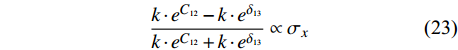
$$ \dfrac{{k \cdot {e^{{C_{12}}}} - k \cdot {e^{{\delta _{13}}}}}}{{k \cdot {e^{{C_{12}}}} + k \cdot {e^{{\delta _{13}}}}}} \propto \sigma_{x} $$ (23) 通过采集的电容值便可计算得出
$\beta $ 从而获取焊枪的横向偏移量以及偏移方向,再通过曲线拟合、非线性提取等数值处理,从多极阵列电容传感器获取的电容值便可获得判断焊枪的高低、左右偏移及偏移方向的信息,实现窄间隙焊缝跟踪.4. 试验平台搭建
4.1 试验平台
为检测多极阵列电容传感器在试验过程中的可靠性,搭建位移调试平台和焊接试验平台. 试验平台装置包含多极阵列电容传感器、STM32F103R单片机运算系统[12]、位移平台CNC405057[13]等,可实现焊接和非焊接条件下,电容传感器采集数据的变化趋势. 其中,焊接小车运行速度为2 ~ 5 mm/s,水平与垂直可调距离为20 mm;窄间隙焊缝底部宽度8 mm,深度15 mm,传感器距离被测工件15 mm. 为了实现该平台偏移范围的可调节性,装置采用三向结构雕刻机实现高精度位移调节,设置单点移动步距在0.001 mm ~ 10 mm范围可调,横向位移范围为500 mm,高度行程范围为80 mm.
针对焊接试验平台,经过噪声测试,温度和焊接条件影响等分析后,确定AD7745补偿和软件低通滤波处理后,多极阵列电容传感器能够应用于实际焊接生产环境.
4.2 焊缝偏差信号提取
根据传感器原理初步判断焊枪偏移方向后,对焊枪左右偏差和高度距离进行试验.
4.2.1 左右偏差试验
当焊枪左偏时,
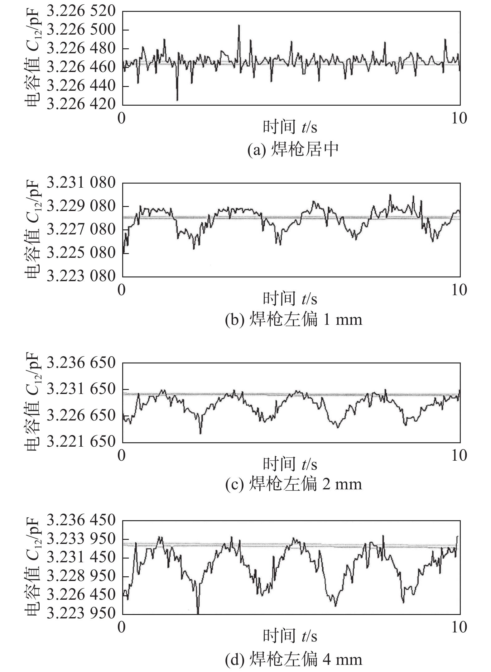
$C_{12}$ 值较大,变化更明显. 因此实验以左偏时$C_{12}$ 容值作为参考.在焊接试验中,设置焊枪底部距离工件最低点的高度为16 mm,为了检测工件从左至右的结构,可以重复4次调节十字滑块移动来实现. 可得如图9所示焊接试验中焊枪横向偏移曲线以及表1中的不同横向偏差下的电容值.
![]() 图 9 焊枪产生横向偏差时C12值变化曲线Figure 9. Change curve of C12 value when lateral deviation of welding gun occurs. (a) welding torch in the center; (b) welding gun deviates 1 mm to the left; (c) welding gun deviates 2 mm to the left; (d) welding gun deviates 4 mm to the left表 1 焊枪不同横向/纵向时偏差电容值变化(pF)Table 1. Variation of deviation capacitance value of welding gun in different lateral/longitudinal directions
图 9 焊枪产生横向偏差时C12值变化曲线Figure 9. Change curve of C12 value when lateral deviation of welding gun occurs. (a) welding torch in the center; (b) welding gun deviates 1 mm to the left; (c) welding gun deviates 2 mm to the left; (d) welding gun deviates 4 mm to the left表 1 焊枪不同横向/纵向时偏差电容值变化(pF)Table 1. Variation of deviation capacitance value of welding gun in different lateral/longitudinal directions焊枪偏差距离 初始值C0 最大值Cmax 差值ΔC 居中 3.226 420 3.226 520 0.000 1 左偏1 mm 3.226 080 3.229 030 0.002 95 左偏1 mm 3.226 080 3.229 030 0.002 95 左偏2 mm 3.225 15 3.230 40 0.005 25 左偏4 mm 3.226 80 3.233 95 0.007 15 上偏5 mm 3.226 450 3.229 050 0.002 60 上偏10 mm 3.226 500 3.239 000 0.012 50 如图9和表1,当焊枪对中焊缝时的电容值变化极小,焊缝偏差变化范围符合焊缝跟踪精度. 当焊枪向左偏移时,在一个试验扫面周期中,
$C_{12}$ 逐渐增大后又减小到原的大小值,且随着焊枪偏差距离增大,电容初始值与最大值之间的差值也逐渐增大.4.2.2 高低偏差试验
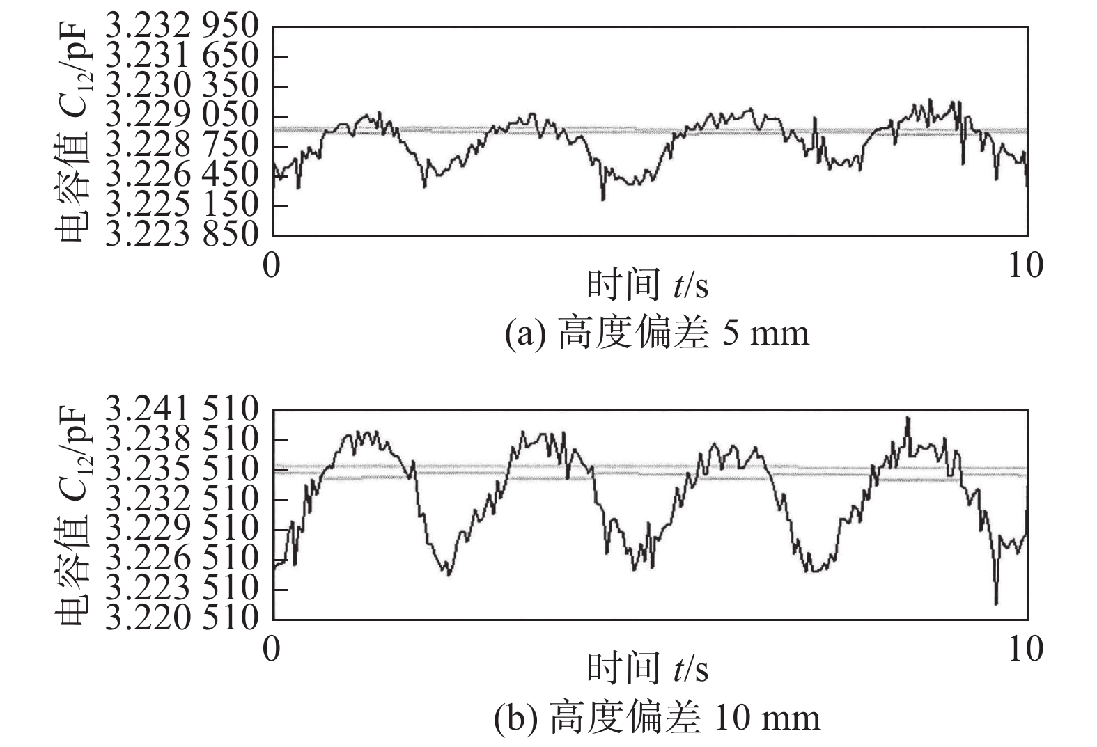
当焊枪高低产生变化时,
$C_{12}$ 相同,试验取$C_{12}$ 为参考,最大高度偏差分别设置为5 mm和10 mm,焊枪相对于焊缝底部垂直移动,重复4次试验,循环时间间隔2.5 s,试验系统连续采集电容值信号,其信号值如图10和表1所示.![]() 图 10 焊枪产生纵向偏差时C12值变化曲线Figure 10. C12 value variation curve when welding gun produces longitudinal deviation. (a) height deviation of 5 mm; (b) height deviation of 10 mm
图 10 焊枪产生纵向偏差时C12值变化曲线Figure 10. C12 value variation curve when welding gun produces longitudinal deviation. (a) height deviation of 5 mm; (b) height deviation of 10 mm从图10与表1可知,当焊枪高度产生偏差时,在一个试验扫描周期中,C12的值逐渐增大后又减小到原来的大小值,与产生横向偏差时类似,焊枪离焊缝中心越远,电容最大值与初始值之间的差值越大.
根据上述偏差试验可知,电容变化规律与焊枪循环周期基本吻合,且焊枪偏离焊缝中心越远,电容峰值将会越大;不同焊枪偏差条件下,在不同的循环周期内,电容值随偏差距离改变而改变,且与扫描焊缝规律基本趋同,因此文中所述的焊缝跟踪系统可以稳定识别焊缝偏差,具有一定可靠性.
根据式(21)~式(23),设h0 = 15,
$\sigma_{x_0} $ = 10。分析多组试验数据,求出待定系数δ,k,α,β,k = 0.01;α = 0.864;β = 0.025;δ = 1.026。经过试验后选取20组不同的电容值,通过分析与处理初步重建焊缝三维模型如图5b所示。窄间隙焊缝重建后焊缝宽度基本等于8 mm,与位移调试平台(图9)中的窄间隙焊缝(图5a)基本一致。5. 结论
(1)优化得到了适用于窄间隙焊缝跟踪的多极阵列电容传感器结构:三电极均匀分布,电极、径向保护层及电容顶层保护厚度分别取2,1,1 mm,极板覆盖率取90%.
(2)基于小波滤波和非线性映射技术实现了多极阵列电容传感器在窄间隙焊缝跟踪中的电容信号处理,获得了焊缝横向和纵向偏移信息.
(3)搭建了焊缝偏差检测试验平台,分析电容值进一步获取焊枪空间位置信息,重构了焊缝坡口形貌,验证了多极阵列相电容传感器可于适配窄间隙焊缝跟踪系统.
-
![]()
图 1 电极结构简图
Figure 1. Electrode structure diagram. (a) cross section of electrode; (b) three-dimensional structure of electrodes
![]()
图 3 电容传感器在窄间隙焊缝中的空间位置关系
Figure 3. Spatial position relationship of the capacitance sensor in the narrow gap weld. (a) welding gun in the center; (b) welding gun offset to the lefto, welding gun offset to the right; (c) welding gun offset upwards, welding gun downward offset
![]()
图 4 极板覆盖率不等时水平横截面电势分布图
Figure 4. Equipotential distribution map of horizontal cross-section with unequal plate coverage. (a) pole plate coverage of 50%; (b) pole plate coverage of 75%; (c) pole plate coverage of 90%
![]()
图 5 窄间隙焊缝模型与坡口模型重建
Figure 5. Narrow gap weld model diagram and reconstruction of groove model variation of the lateral and longitudinal offsets. (a) narrow gap weld model diagram; (b) reconstruction diagram of groove model
![]()
图 6 焊缝横向及纵向偏移时电容
$C_{12}$ 化曲面图Figure 6. Curve of capacitance C12 variation when the welding gun deviates horizontally and longitudinally
![]()
图 7 电容值横向偏差下非线性映射点拟合曲线图
Figure 7. Nonlinear mapping point fitting curve of capacitance value under lateral deviation
![]()
图 9 焊枪产生横向偏差时C12值变化曲线
Figure 9. Change curve of C12 value when lateral deviation of welding gun occurs. (a) welding torch in the center; (b) welding gun deviates 1 mm to the left; (c) welding gun deviates 2 mm to the left; (d) welding gun deviates 4 mm to the left
![]()
图 10 焊枪产生纵向偏差时C12值变化曲线
Figure 10. C12 value variation curve when welding gun produces longitudinal deviation. (a) height deviation of 5 mm; (b) height deviation of 10 mm
表 1 焊枪不同横向/纵向时偏差电容值变化(pF)
Table 1 Variation of deviation capacitance value of welding gun in different lateral/longitudinal directions
焊枪偏差距离 初始值C0 最大值Cmax 差值ΔC 居中 3.226 420 3.226 520 0.000 1 左偏1 mm 3.226 080 3.229 030 0.002 95 左偏1 mm 3.226 080 3.229 030 0.002 95 左偏2 mm 3.225 15 3.230 40 0.005 25 左偏4 mm 3.226 80 3.233 95 0.007 15 上偏5 mm 3.226 450 3.229 050 0.002 60 上偏10 mm 3.226 500 3.239 000 0.012 50  下载: 导出CSV
-
[1] Sproesser G, Chang Yaju, Pittner A, et al. Life cycle assessment of welding technologies for thick metal plate welds[J]. Journal of Cleaner Production, 2015, 108: 46 − 53. doi: 10.1016/j.jclepro.2015.06.121
[2] Liu Wenji, Li Liangyu, Yue Jianfeng, et al. Research on the “jump sidewall” behavior and its signal characteristics in narrow gap P-MAG welding[J]. The International Journal of Advanced Manufacturing Technology, 2017, 91(1-4): 1189 − 1196.
[3] 洪波, 戴威, 李湘文, 等. 窄间隙埋弧焊的磁控与电感复合式焊缝跟踪方法[J]. 焊接学报, 2016, 37(1): 11 − 14. Hong Bo, Dai Wei, Li Xiangwen, et al. Magnetic control and inductance combined welding seam tracking method for narrow gap submerged arc welding[J]. Transactions of the China Welding Institution, 2016, 37(1): 11 − 14.
[4] Yang Wuxiong, Xin Jijun, Fang Chao, et al. Microstructure and mechanical properties of ultra-narrow gap laser weld joint of 100 mm-thick SUS304 steel plates[J]. Journal of Materials Processing Technology, 2019(25): 130 − 137.
[5] Liu Guoqiang, Tang Xinhua, Han Siyuan, et al. Influence of interwire distance and arc length on welding process and defect formation mechanism in double-wire pulsed narrow-gap gas metal arc welding[J]. Journal of Materials Engineering and Performance, 2021(30): 7622 − 7635.
[6] 洪波, 言浚光, 阳佳旺, 等. 一种用于焊缝跟踪的电容式传感器[J]. 焊接学报, 2014, 35(2): 55 − 58. Hong Bo, Yan Junguang, Yang Jiawang, et al. A capacitive sensor for welding seam tracking[J]. Transactions of the China Welding Institution, 2014, 35(2): 55 − 58.
[7] 李湘文, 陶韬, 洪波, 等. 基于薄板搭接的摆动式相邻电容焊缝跟踪传感器[J]. 焊接学报, 2017, 38(9): 61 − 64. doi: 10.12073/j.hjxb.20151126005 Li Xiangwen, Tao Tao, Hong Bo, et al. Swing type adjacent capacitor welding seam tracking sensor based on thin plate lap joint[J]. Transactions of the China Welding Institution, 2017, 38(9): 61 − 64. doi: 10.12073/j.hjxb.20151126005
[8] 洪波, 朱亚飞, 李湘文, 等. 电容电感复合桥式焊缝跟踪传感器[J]. 焊接学报, 2015, 36(4): 9 − 12. Hong Bo, Zhu Yafei, Li Xiangwen, et al. Capacitance and inductance composite bridge welding seam tracking sensor[J]. Acta China Welding Institution, 2015, 36(4): 9 − 12.
[9] 王大伦. 电动力学教程[M]. 湘潭: 湘潭大学出版社, 2017: 47-48. Wang Dalun. Electrodynamics tutorial[M]. Xiangtan: Xiangtan University Press, 2017: 47-48.
[10] 谢东, 李昌禧. 同面散射场电容式砂含水量传感器的研究[J]. 传感技术学报, 2008, 21(12): 2000 − 2004. doi: 10.3969/j.issn.1004-1699.2008.12.010 Xie Dong, Li Changxi. Research on capacitive sand moisture content sensor with co-planar scattering field[J]. Journal of Sensor Technology, 2008, 21(12): 2000 − 2004. doi: 10.3969/j.issn.1004-1699.2008.12.010
[11] 吴云靖, 董恩生, 庞宇, 等. 基于ANSYS的同面多电极电容传感器仿真研究[J]. 计测技术, 2010, 30(4): 9 − 11. doi: 10.3969/j.issn.1674-5795.2010.04.004 Wu Yunjing, Dong Ensheng, Pang Yu, et al. Simulation research of multi-electrode capacitance sensor on the same plane based on ANSYS[J]. Measurement Technology, 2010, 30(4): 9 − 11. doi: 10.3969/j.issn.1674-5795.2010.04.004
[12] 黄林, 陈向东, 谢宁宁, 等. 基于AD7150微位移电容传感器的研究[J]. 半导体技术, 2012, 37(6): 425 − 428. doi: 10.3969/j.issn.1003-353x.2012.06.003 Huang Lin, Chen Xiangdong, Xie Ningning, et al. Research on micro displacement capacitance sensor based on AD7150[J]. Semiconductor technology, 2012, 37(6): 425 − 428. doi: 10.3969/j.issn.1003-353x.2012.06.003
[13] Schmitt D, Novak J, Maslakowski J, et al. Automating a precision braze paste dispensing operation using non-contact sensing[R]. Albuquerque: Sandia National Labs, 1993.
-
期刊类型引用(1)
1. 林溥祥,刘文吉,高鹏,刘育耕. 无位置信号的P-GMAW摆动电弧传感焊缝跟踪方法研究. 仪表技术与传感器. 2025(04): 121-126 .  百度学术
百度学术
其他类型引用(0)


计量
- 文章访问数: 344
- HTML全文浏览量: 108
- PDF下载量: 47
- 被引次数: 1
