Forming characteristics of bypass coupling triple-wire gas indirect arc additive manufacturing
-
摘要: 采用旁路耦合三丝间接电弧焊( bypass coupling triple-wire gas indirect arc welding,BCTW-GIA焊)进行Q345低碳钢增材制造. 利用高速成像设备研究了旁路电流变化对电弧特性的影响,并观察了对应的焊缝成形特性. 结果表明,随着旁路电流的增加,间接电弧占比逐渐减少,而直接电弧占比逐渐增加,焊接热输入逐步提升,焊缝的接触角逐渐减小. 当旁路电流为155 A时,可在表面成形良好的前提下得到铺展性最优的单道焊缝. 采用此参数进行单道多层增材得到了直壁墙体,沉积速率高达13.3 kg/h. 该增材制造方法具有较高的熔敷效率和较低的热输入,有利于改善增材试样的显微组织,并提高试样的平均硬度. 试样底部、中部及顶部区域的平均硬度分别为 186.80,172.44,176.04 HV.
-
关键词:
- 电弧增材制造 /
- 旁路耦合三丝间接电弧焊 /
- 电弧特性 /
- 成形特性
Abstract: The additive manufacturing of Q345 low carbon steel using bypass coupling triple-wire gas indirect arc welding (BCTW-GIA) is reported. The influence of bypass current variation on arc characteristics is studied by using high-speed imaging equipment, and the corresponding formimg characteristics of beads are observed. The results show that with the increase of bypass current, the gradual increases happen to the proportion of direct arc and the welding heat input, however the gradual decreases happen to the proportion of indirect arc and the contact angle of the beads. When the bypass current is 155 A, a single-pass welding bead with the best spreadability can be obtained under the premise of good forming surface. Based on this set of parameters, the straight wall can be acquired by single pass and multi-layer additive manufacturing with a deposition rate as high as 13.3 kg/h. The high cladding efficiency and low heat input of the additive manufacturing method are conducive to improving the microstructure of the additive samples and increasing the average hardness. The average hardnesses of the bottom, middle and top areas of the sample are 186.80, 172.44 and 176.04 HV, respectively. -
0. 序言
增材制造是一种通过自下而上逐层累积实现近净成形的高效制造技术[1]. 在金属加工领域,增材制造技术依据热源种类可分为激光、电子束及电弧3类[2]. 其中电弧增材制造技术凭借较高的制造效率及较低的成本近年来在大尺寸零件制造领域蓬勃发展[3-4]. 传统的电弧熔丝增材制造为了提高沉积速率,经常伴随送丝速度和焊接电流的提升,使沉积件热输入增加,导致零件的成形质量降低[5]. 为此学者们将双丝电弧焊[6]、旁路耦合电弧焊[7-8]、双丝间接电弧焊[9]以及热电冷却电弧焊[10]等技术应用到此领域,一定程度上降低了沉积过程中的热输入,但在沉积速率的进一步提升方面仍有待研究.
三丝间接电弧焊(triple-wire gas indirect arc welding, TW-GIA焊)是一种高熔覆效率、低热输入的新型焊接方法[11]. 国内已有学者对该技术的工艺进行了优化,提高了其焊接过程中的稳定性与适应性. Liu等人[12-13]调整了该技术的焊丝排布方式,从而得到了更高的熔敷效率,还研究了焊丝极性连接方式,结果表明,主丝接负的焊丝极性接法可使所得焊缝的铺装性能提升,深宽比降低. 王泽力等人[14]发现该技术具有热输入小的特点,对焊缝及热影响区组织晶粒起到细化作用. Liu 等人[15]改进了焊接电流等主要工艺参数,并将该技术成功推广到2 mm薄板高速焊接领域. 于世宝等人[16]发现采用较高的脉冲频率能提高焊丝燃烧均匀程度,更有利于形成均一的焊道. 刁国宁等人[17]发现当三丝采用相等的焊丝伸出长度时,电弧的稳定性及焊缝成形情况更好. 然而,在将TW-GIA焊应用于增材制造领域的前期探究过程中发现,由于该技术具有熔覆效率高、热输入小的特点,其单道焊缝接触角大于90°,在较大的电弧吹力下,易出现侧流缺陷,无法实现有效的逐层堆敷.
在TW-GIA焊基础上提出了旁路耦合三丝间接电弧焊(bypass coupling triple-wire gas indirect arc welding, BCTW-GIA焊),即通过旁路系统调节TW-GIA焊的焊接热输入,以改善焊缝的铺展性能,并将其应用于增材制造领域,展示了一种低热输入、高沉积速率的新型增材制造方法. 研究旁路电流对BCTW-GIA焊电弧形态及焊缝成形的影响,并采用最优参数实现了直壁墙体的高效增材,为该方法在增材制造领域的应用奠定基础.
1. 试验方法
图1为BCTW-GIA焊增材制造系统示意图,主要由2台焊机及3根焊丝组成. 焊机采用直流-脉冲电源模式以促进熔滴过渡,左边丝连接直流电源的正极,右边丝连接脉冲直流电源的正极,主丝与基板均连接两电源负极. 其中,左边丝电流I1 与右边丝电流的平均值I2相等,二者之和为总电流I. 起弧后,两边丝的电流一部分经过主丝流向电源负极形成主回路,另一部分经过增材件及基板后流向电源负极形成旁路,主丝电流Im 与旁路电流Ip 的和等于I.
试验选用尺寸为200 mm × 150 mm × 10 mm的Q345钢作为基板,焊丝牌号为ER50-6,基板和焊丝成分如表1所示. 保护气体成分为80% Ar + 20% CO2,气体流量25 L/min. 主丝直径为1.6 mm,边丝直径为1.2 mm. 主丝与水平面夹角为45°,两边丝呈镜面对称式分布于主丝两侧,与主丝的丝间夹角为30°. 三丝交点到基板的垂直距离即焊枪高度为5 mm,焊接速度为1 m/min. 同时保持两台焊机输出的平均电流恒为180 A,两边丝送丝速度恒为5.8 m/min. 主丝送丝速度与主丝电流成正比,主丝电流越大,主丝送丝速度越大,同时旁路电流将减小. 具体试验工艺参数如表2所示. 采用MS50K高速摄影机垂直于焊接方向拍摄,采集不同参数对应的电弧特性,采样频率2000 帧/s.
表 1 基板和焊丝化学成分 (质量分数,%)Table 1. Chemical compositions of base metal and wire材料 C Mn Si S P Fe Q345 ≤0.2 ≤1.7 ≤0.5 ≤0.035 ≤0.035 余量 ER50-6 0.1 1.54 0.9 0.02 0.18 余量 表 2 不同旁路电流对应的试验工艺参数Table 2. Test parameters corresponding to different bypass currents旁路电流
Ip/A主丝电流
Im/A主丝送丝速度vfm/(m·min−1) 边丝送丝速度vfs/(m·min−1) 焊接速度v/(m·min−1) 0 360 6.5 5.8 1 75 285 11 5.8 1 115 245 9.5 5.8 1 155 205 8 5.8 1 195 165 5 5.8 1 360 0 0 5.8 1 2. 试验结果与分析
2.1 单道焊缝成形情况
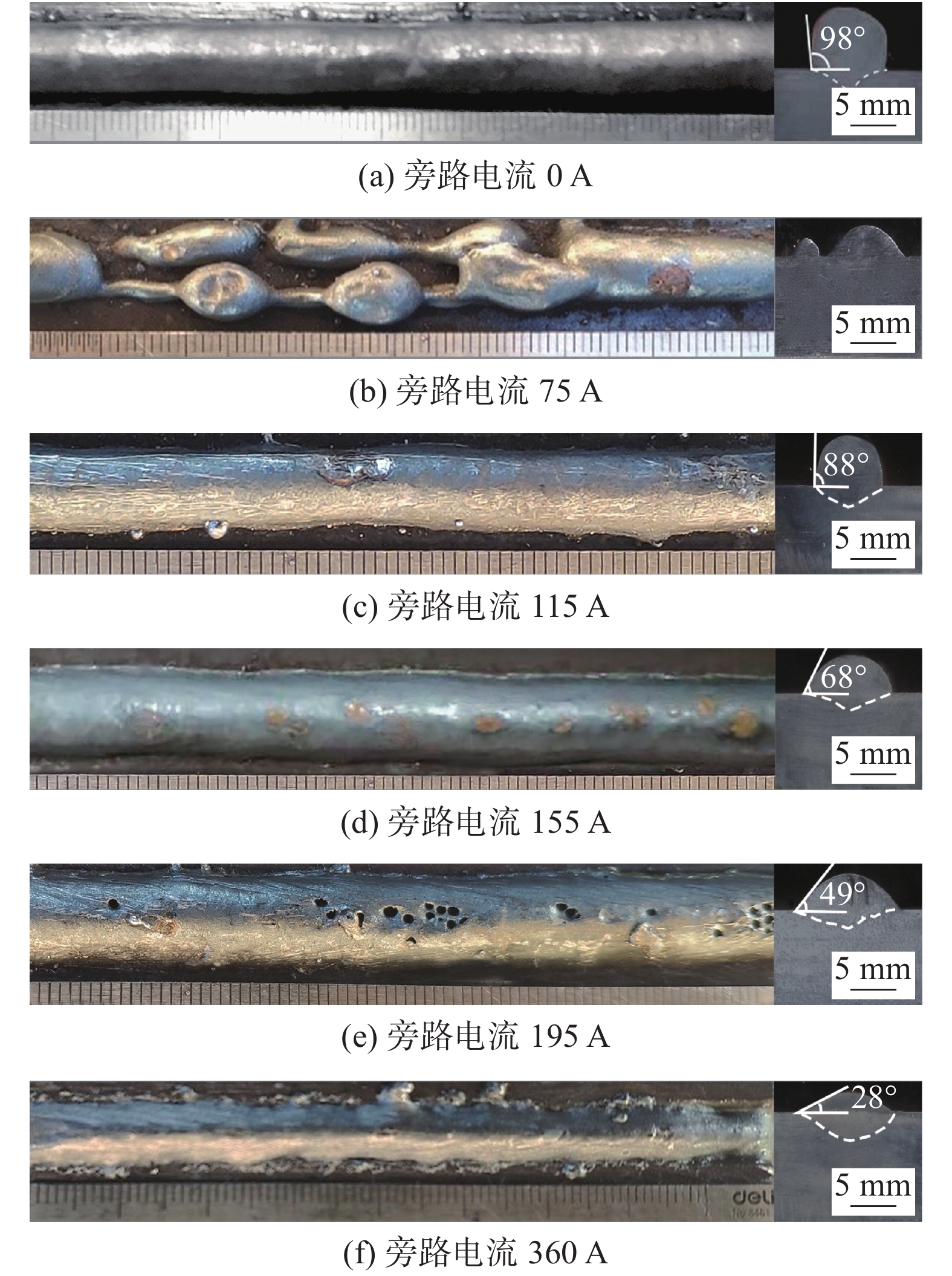
图2为不同旁路电流下的单道单层堆焊试样的表面及截面形貌.在旁路电流为0 A时,三丝间接电弧可以获得良好的焊缝表面形貌,但是由于间接电弧的热输入低,单道熔覆铺展性能较差,其接触角大于90°,不利于后续逐层堆覆过程的稳定进行. 当旁路电流为75 A时,试样表面断续,无法连续成形;当旁路电流为115和155 A时可以获得成形良好的焊缝,其焊道与基板的接触角均小于90°. 当旁路电流增大到195 A时,试样表面出现孔洞;当旁路电流进一步增大到360 A时,试样表面出现明显的飞溅及咬边.
表3为不同旁路电流下的单道单层试样成形尺寸,该尺寸是通过AI软件测量经过腐蚀后的堆焊试样截面的视觉图像,并按比例计算而得到的.可以看出,随着旁路电流的增加,堆积焊道的余高逐渐减小,熔宽逐渐增加,接触角逐渐变小,铺展性能增加,熔深先减小后增大. 在没有缺陷的前提下,当旁路电流为155 A时,焊道接触角最小,有利于后续逐层堆覆过程的稳定进行.
表 3 不同旁路电流下单道焊缝成形尺寸Table 3. Forming dimensions of single bead under different bypass currents旁路电流
Ip/A熔宽
W/mm熔深
d/mm余高
h/mm接触角
θ/(°)0 7.90 2.40 5.60 98 75 — — — — 115 7.02 2.02 5.12 88 155 9.13 1.60 4.13 68 195 9.80 1.55 3.45 49 360 9.12 2.50 1.85 28 2.2 旁路电流对电弧特性的影响
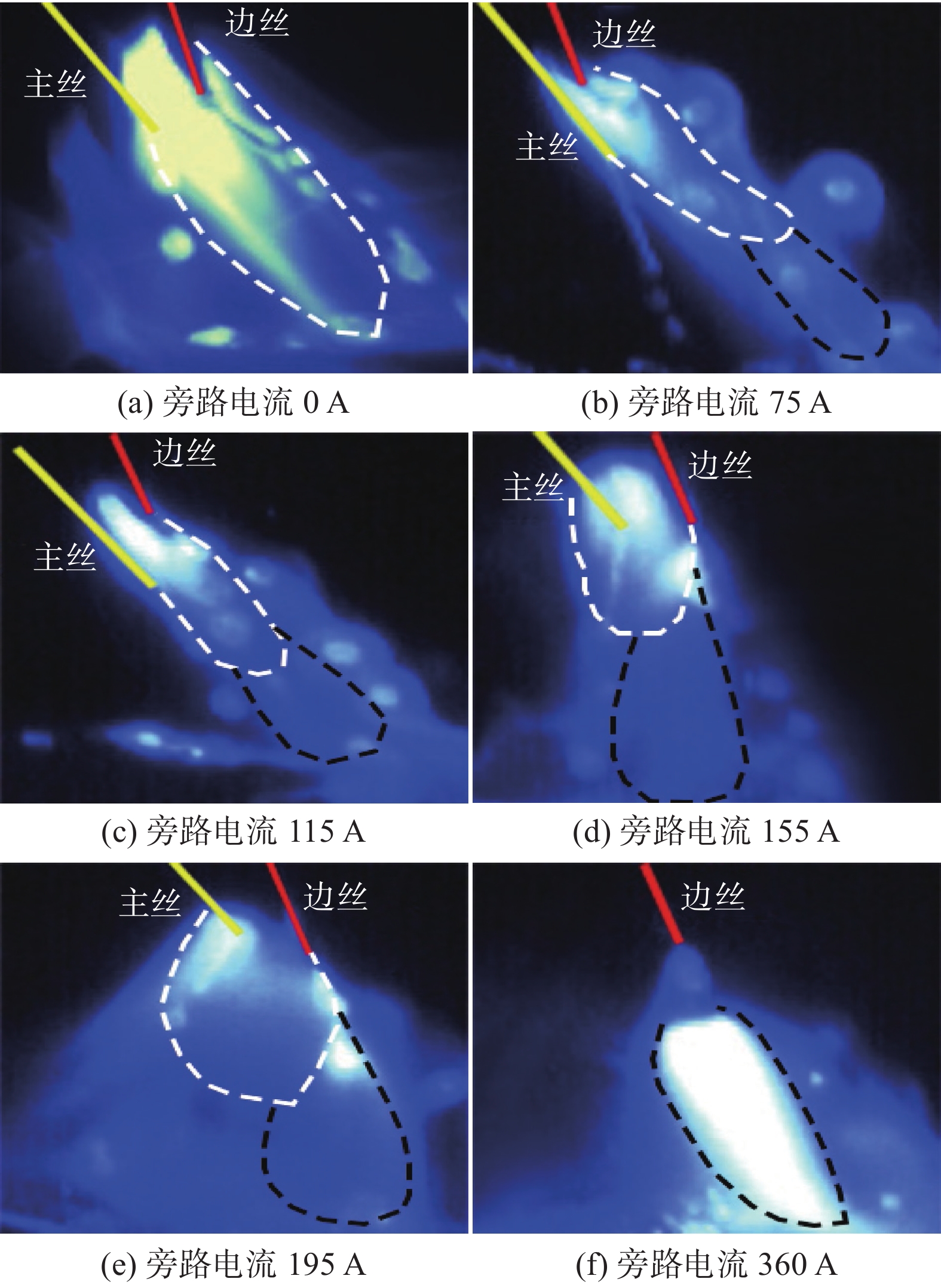
堆焊试样的表面形貌决定于电弧形态及熔滴过渡行为,图3为不同旁路电流对应的电弧形态,图中白色虚线代表主丝与两边丝之间形成的间接电弧,黑色虚线代表基板与两边丝之间形成的电弧. 可以看出,随着旁路电流的增加,间接电弧所占比例逐渐减少,焊接热输入逐步提升. 当旁路电流为0 A时,相当于采用TW-GIA焊模式施焊,此时只有间接电弧存在,电流不过基板,热输入较小,因此此时的焊缝虽然表面形貌较好,但是铺展性能差,如图3a所示.当旁路电流为75 A时,主丝送丝速度较大,间接电弧被挤压,偏向边丝一侧,边丝熔滴所受的排斥力较大,出现多条过渡路径,致使对应堆焊试样断续,如图3b所示. 当旁路电流为115和155 A时,电弧及熔滴过渡的稳定性较为良好,因而焊缝表面形貌较好,如图3c和图3d所示. 当旁路电流为195 A时,主丝送丝速度过小,间接电弧向主丝的偏转程度过大,电弧整体过于发散,稳定性差,导致堆焊试样表面出现孔洞缺陷,如图3e所示.当旁路电流进一步增至360 A时,间接电弧消失,系统总电流全部经旁路流过基板,热输入过大,致使试样表面出现大量咬边缺陷,如图3f所示.
相对于旁路电流115 A,当旁路电流为155 A时,可在保证电弧稳定性及焊缝成形情况的前提下,通过微增旁路电流使焊接热输入及电弧发散性小幅度增加,从而得到熔宽更大,熔深及接触角更小的焊缝,因此最终选用旁路电流为155 A的参数进行后续的增材试验.
2.3 单道多层增材试验
2.3.1 单道多层试样成形情况
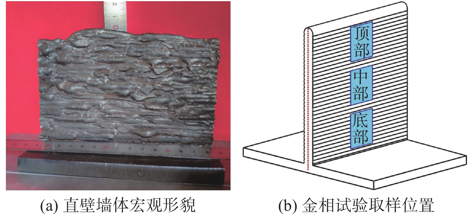
当旁路电流为155 A时,单道堆焊试样的表面形貌良好,并且润湿性能较好,前一层熔覆层的表面可以为后一层熔覆金属提供足够的支撑面积,有利于逐层沉积过程的稳定进行;另外,该参数下熔深较小,逐层沉积过程中,后一层对前一层的重熔作用最小. 因此,为验证该工艺对大尺寸零件增材制造的适用性,采用155 A的旁路电流进行单道多层沉积试验,所得直壁墙体宏观形貌如图4所示,沉积速度为1 m/min,沉积层数为35层,每层抬高量为3 mm,层间冷却时间30 s,最终得到表面成形较为良好、成形高度为9.7 cm、平均有效宽度为7.2 mm的直壁墙体.
2.3.2 显微组织分析
图5为直壁墙体不同部位的显微组织,取样位置如图4b所示,由图5可知,试样各部位显微组织主要由呈白色的铁素体、呈灰暗色的珠光体以及少量白色棱角分明的残余奥氏体组成. 试样各部位组织均未发现魏氏铁素体,表明堆覆过程中不存在过热现象.
在直壁墙体的底部区域(图5a),铁素体的晶粒细小,珠光体的沿晶分布的均匀性较好,无残余奥氏体存在;在直壁墙体的中部区域(图5b),铁素体晶粒变得粗大,珠光体分布的均匀性降低,并出现少量的残余奥氏体;在直壁墙体的顶部区域(图5c),铁素体大部分呈细小的块状,珠光体沿晶分布且均匀性低,仍存在少量的残余奥氏体;在两层交界附近(图5d),前堆积层的等轴晶组织明显粗化,后堆积层依附于前堆积层的表面以柱状晶的形式生长,延伸到后堆积层的内部后形成等轴晶.
2.3.3 显微硬度分析
图6为沿着直壁墙体截面的垂直中心线上的显微硬度分布曲线,可以看出,基板附近区域的局部硬度很高,随着距基板表面的距离的增加,硬度整体上呈现先降低,最后在接近直壁墙体顶部时波动回升的趋势,试样底部、中部及顶部区域的平均硬度分别为186.80,172.44,176.04 HV. 此外,通过观察还可以发现,硬度曲线每间隔3 ~ 4 mm都会呈现出先下降后上升的锯齿状周期性变化.
直壁墙体纵向不同位置处的沉积层,经历的热循环次数、热处理条件和凝固速度的差异是造成其硬度不同的根本原因. 在沉积的初始几层,散热方式为三维散热,凝固速度快,使得直壁墙体前几层的晶粒细小,并且在后续沉积层的热处理作用下,组织更为细小均匀(图5a),因此底层区域的硬度较高;随着沉积过程的进行,直壁墙体的热量积累越发严重,散热方式变为一维散热,凝固速度下降,晶粒粗化(图5b),铁素体沿着散热方向析出呈粗大板条状,使得该部分硬度降低;在接近直壁墙体顶部的位置处,由于后续熔敷层的热处理作用减弱,加上气体流动增强、散热转变为三维散热,凝固速率过快,晶粒细化(图5c),因而硬度相比于中部区域有一定的回升,但由于该部位组织均匀性差,因此其硬度的波动程度较大.
此外,硬度曲线的锯齿状周期性变化趋势是由于该焊接方法较高的熔覆效率和较低的热输入造成的,两道沉积层交界处与每一道沉积层内部的组织存在差异(图5d),这对提高试样的平均硬度有利.
2.4 沉积速率计算及分析
BCTW-GIA焊的沉积速率E可由公式(1)计算得出.
$$ E={\text{π}} \rho \left(v_{{\rm{fm}}} {r_{{\rm{m}}}}^{2} + 2 v_{{\rm{fs}}} {r_{{\rm{s}}}}^{2}\right) $$ (1) 式中:vfm,vfs分别为主丝和边丝的送丝速度;rm,rs分别为主丝和边丝半径;ρ为焊丝密度,计算可得连续沉积速率为13.3 kg/h. 表4列举了BCTW-GIA焊、熔化极气体保护焊增材制造(gas metal arc welding-additive manufacturing,GMA-AM)、冷金属过渡焊增材制造(cold metal transfer-additive manufacturing,CMT-AM)以及串联双丝GMA-AM的连续沉积速率. 从表4可见,与其它几种GMA-AM相比,采用BCTW-GIA焊方法可使沉积速率有明显的提高[18-20]. 此外,由于间接电弧存在,当增大总焊接电流而提升沉积速率的同时,可以调节主丝电流进行分流,使旁路电流值保持在适宜范围内,避免因热输入过大而导致沉积件出现成形不良等问题.
表 4 几种不同增材制造方法的连续沉积速率Table 4. Continuous deposition rate of several different additive manufacturing methods方法 填充材料 焊丝直径d/mm 送丝速度vs/(m·min−1) 沉积速率E/(kg·h−1) 单丝GMA-AM H08Mn2Si焊丝 1.2 6 3.2 单丝CMT-AM ER100高强钢焊丝 1.2 10 5.3 串联双丝GMA-AM 17-4 PH不锈钢焊丝 1.2 9 9.5 BCTW-GIA焊 ER50-6焊丝 1.6 (主丝);1.2 (两边丝) 8 (主丝);5.8 (两边丝) 13.3 3. 结论
(1) 基于BCTW-GIA焊的Q345低碳钢增材制造,当保持其它参数不变,调节旁路电流至155 A,焊接电弧的稳定性以及集中程度最为适宜,焊缝成形情况最优,所得增材件成形质量良好,连续沉积速率高达13.3 kg/h.
(2) 显微组织分析表明,BCTW-GIA焊较低的热输入使试样显微组织中等轴晶区范围更大,粗大柱状晶区范围更小,并且存在少量残余奥氏体.
(3) BCTW-GIA焊较高的熔覆效率和较低的热输入提高了试样整体的平均硬度,由底部、中部到顶部,直壁墙体平均硬度先降低后增加,依次为 186.80,172.44,176.04 HV.
-
表 1 基板和焊丝化学成分 (质量分数,%)
Table 1 Chemical compositions of base metal and wire
材料 C Mn Si S P Fe Q345 ≤0.2 ≤1.7 ≤0.5 ≤0.035 ≤0.035 余量 ER50-6 0.1 1.54 0.9 0.02 0.18 余量 表 2 不同旁路电流对应的试验工艺参数
Table 2 Test parameters corresponding to different bypass currents
旁路电流
Ip/A主丝电流
Im/A主丝送丝速度vfm/(m·min−1) 边丝送丝速度vfs/(m·min−1) 焊接速度v/(m·min−1) 0 360 6.5 5.8 1 75 285 11 5.8 1 115 245 9.5 5.8 1 155 205 8 5.8 1 195 165 5 5.8 1 360 0 0 5.8 1 表 3 不同旁路电流下单道焊缝成形尺寸
Table 3 Forming dimensions of single bead under different bypass currents
旁路电流
Ip/A熔宽
W/mm熔深
d/mm余高
h/mm接触角
θ/(°)0 7.90 2.40 5.60 98 75 — — — — 115 7.02 2.02 5.12 88 155 9.13 1.60 4.13 68 195 9.80 1.55 3.45 49 360 9.12 2.50 1.85 28 表 4 几种不同增材制造方法的连续沉积速率
Table 4 Continuous deposition rate of several different additive manufacturing methods
方法 填充材料 焊丝直径d/mm 送丝速度vs/(m·min−1) 沉积速率E/(kg·h−1) 单丝GMA-AM H08Mn2Si焊丝 1.2 6 3.2 单丝CMT-AM ER100高强钢焊丝 1.2 10 5.3 串联双丝GMA-AM 17-4 PH不锈钢焊丝 1.2 9 9.5 BCTW-GIA焊 ER50-6焊丝 1.6 (主丝);1.2 (两边丝) 8 (主丝);5.8 (两边丝) 13.3 -
[1] Ngo T D, Kashani A, Imbalzano G, et al. Additive manufacturing (3D printing): A review of materials, methods, applications and challenges[J]. Composites Part B:Engineering, 2018, 143: 172 − 196. doi: 10.1016/j.compositesb.2018.02.012
[2] Frazier W E. Metal additive manufacturing: A review[J]. Journal of Materials Engineering and Performance, 2014, 23(6): 1917 − 1928. doi: 10.1007/s11665-014-0958-z
[3] 耿海滨, 熊江涛, 黄丹, 等. 丝材电弧增材制造技术研究现状与趋势[J]. 焊接, 2015(11): 17 − 21. Geng Haibin, Xiong Jiangtao, Huang Dan, et al. Research status and trend of wire arc additive manufacturing[J]. Welding & Joining, 2015(11): 17 − 21.
[4] Rodrigues T A, Duarte V, Miranda R M, et al. Current status and perspectives on wire and arc additive manufacturing (WAAM)[J]. Materials, 2019, 12(7): 1121.
[5] Yang D, Wang G, Zhang G. A comparative study of GMAW-and DE-GMAW-based additive manufacturing techniques: thermal behavior of the deposition process for thin-walled parts[J]. The International Journal of Advanced Manufacturing Technology, 2017, 91(5-8): 2175 − 2184. doi: 10.1007/s00170-016-9898-0
[6] Wu W, Xue J, Yao P. A comparative study on single- and double-arc deposition processes[J]. Materials and Manufacturing Processes, 2020, 35(3): 346 − 353.
[7] Miao Y, Li C, Yin C, et al. Joint characteristics of carbon steel bypass-current PAW on additive manufacturing[J]. Journal of Manufacturing Processes, 2021, 61: 408 − 416. doi: 10.1016/j.jmapro.2020.10.014
[8] 余淑荣, 程能弟, 黄健康, 等. 旁路耦合电弧增材制造热过程与组织关系[J]. 焊接学报, 2019, 40(8): 1 − 6. Yu Shurong, Cheng Nengdi, Huang Jiankang, et al. Relationship between thermal process and microstructure of bypass coupled arc additive manufacturing[J]. Transactions of the China Welding Institution, 2019, 40(8): 1 − 6.
[9] Zuo W, Ma L, Lu Y, et al. Effects of solution treatment temperatures on microstructure and mechanical properties of TIG–MIG hybrid arc additive manufactured 5356 aluminum alloy[J]. Metals and Materials International, 2018, 24(6): 1346 − 1358. doi: 10.1007/s12540-018-0142-3
[10] Li F, Chen S, Shi J, et al. Thermoelectric cooling-aided bead geometry regulation in wire and arc-based additive manufacturing of thin-walled structures[J]. Applied Sciences, 2018, 8(2): 207. doi: 10.3390/app8020207
[11] Fang D, Song G, Liu L. A novel method of triple-wire gas indirect arc welding[J]. Materials and Manufacturing Processes, 2016, 31(3): 352 − 358. doi: 10.1080/10426914.2015.1058949
[12] Liu L, Fang D, Song G. Experimental investigation of wire arrangements for narrow-gap triple-wire gas indirect arc welding[J]. Materials and Manufacturing Processes, 2016, 31(16): 2136 − 2142. doi: 10.1080/10426914.2015.1090603
[13] Liu L, Hu C, Yu S, et al. A triple-wire indirect arc welding method with high melting efficiency of base metal[J]. Journal of Manufacturing Processes, 2019, 44: 252 − 260. doi: 10.1016/j.jmapro.2019.05.022
[14] 王泽力, 张天奕, 刁国宁, 等. 低碳钢三丝间接电弧焊传热机制及工艺性能[J]. 焊接学报, 2022, 43(1): 1 − 6. doi: 10.12073/j.hjxb.20210627001 Wang Zeli, Zhang Tianyi, Diao Guoning, et al. Heat transfer mechanism and mechanical properties of triple-wire gas indirect arc welding for low carbon steel[J]. Transactions of the China Welding Institution, 2022, 43(1): 1 − 6. doi: 10.12073/j.hjxb.20210627001
[15] Liu L, Yu S, Song G, et al. Analysis of arc stability and bead forming with high-speed TW-GIA welding[J]. Journal of Manufacturing Processes, 2019, 46: 67 − 76. doi: 10.1016/j.jmapro.2019.08.023
[16] 于世宝, 赵中秋, 高忠林, 等. 脉冲频率对三丝间接电弧焊稳定性的影响[J]. 焊接学报, 2021, 42(2): 92 − 96. doi: 10.12073/j.hjxb.20180530003 Yu Shibao, Zhao Zhongqiu, Gao Zhonglin, et al. Effect of pulse frequency on the stability of triple-wire indirect arc welding[J]. Transactions of the China Welding Institution, 2021, 42(2): 92 − 96. doi: 10.12073/j.hjxb.20180530003
[17] 刁国宁, 徐国敏, 张天奕, 等. 焊丝伸出长度对三丝间接电弧焊稳定性和焊缝成形的影响[J]. 焊接学报, 2022, 43(3): 31 − 36. doi: 10.12073/j.hjxb.20210926001 Diao Guoning, Xu Guomin, Zhang Tianyi, et al. Effect of wire extension on stability and bead formation of triple-wire gas indirect arc welding[J]. Transactions of the China Welding Institution, 2022, 43(3): 31 − 36. doi: 10.12073/j.hjxb.20210926001
[18] Xiong J, Zhang G, Gao H, et al. Modeling of bead section profile and overlapping beads with experimental validation for robotic GMAW-based rapid manufacturing[J]. Robotics and Computer-Integrated Manufacturing, 2013, 29(2): 417 − 423. doi: 10.1016/j.rcim.2012.09.011
[19] Bourlet C, Zimmer-Chevret S, Pesci R, et al. Microstructure and mechanical properties of high strength steel deposits obtained by wire-arc additive manufacturing[J]. Journal of Materials Processing Technology, 2020, 285: 116759. doi: 10.1016/j.jmatprotec.2020.116759
[20] Martina F, Ding J, Williams S, et al. Tandem metal inert gas process for high productivity wire arc additive manufacturing in stainless steel[J]. Additive Manufacturing, 2019, 25: 545 − 550. doi: 10.1016/j.addma.2018.11.022
-
期刊类型引用(7)
1. 高东,李永利,邓颖,周好斌. 旁路耦合电弧TIG焊原理及工艺研究. 热加工工艺. 2025(01): 65-69 .  百度学术
百度学术
2. 孟美情,韩俭,朱瀚钊,梁哲滔,蔡养川,张欣,田银宝. 基于多丝电弧增材制造研究现状. 材料工程. 2025(05): 46-62 .  百度学术
百度学术
3. 王梦真,万占东,林健. 电弧增材制造工艺及数值仿真研究进展. 大型铸锻件. 2024(01): 7-12 .  百度学术
百度学术
4. 李博洋,巴现礼,陈帅帅,徐国敏,刘黎明. 不同路径下的低碳钢三丝间接电弧增材制造组织与性能. 焊接技术. 2024(10): 1-6+145 .  百度学术
百度学术
5. 张加恒,黄祎,郭顺,杨东青,闫德俊,李东,王克鸿. 超音频MIG辅助三丝电弧增材制造工艺研究. 电焊机. 2023(02): 104-110 .  百度学术
百度学术
6. 吴涛,谭振,王立伟,梁志敏,汪殿龙. 异质双丝间接电弧增材制造Al-Mg-Cu合金组织与力学性能. 焊接学报. 2023(10): 64-70+136 .  本站查看
本站查看
7. 朱强,姚屏,许斯帆,许可昱. 316L不锈钢电弧增材制造工艺研究. 精密成形工程. 2023(11): 164-170 .  百度学术
百度学术
其他类型引用(1)


 下载:
下载:


