
Effect of pin rotational speed on microstructure and properties of SSFSW weld for thick-plate magnesium alloy
-
摘要: 对9 mm厚板AZ31B镁合金进行静止轴肩搅拌摩擦焊(stationary shoulder friction stir welding,SSFSW)工艺试验,探讨搅拌针转速(500 ~ 1000 r/min)对焊缝组织及力学性能的影响规律. 结果表明,在给定焊接速度80 mm/min下,搅拌针转速在600 ~ 800 r/min范围可获得表面光滑、无内部缺陷的对接焊缝,当转速为1 000 r/min时焊缝表面出现不连续凹坑但内部仍无缺陷. 随着转速增加,晶粒尺寸由(11.11 ± 1.68) μm增加到(18.95 ± 1.83) μm;在700 r/min时焊核区晶粒尺寸沿板厚差异最小. 焊缝中间硬度分布具有不均匀性且随转速增加而减小,最大差异为10.97 HV,最低硬度47 HV位于前进侧的热力影响区与焊核区界面处. 在700 r/min下接头力学性能最佳,强度系数为90.2%、对应断后伸长率为母材69.3%. 随着转速增加,断裂模式由韧-脆混合断裂转变为剪切-韧性混合断裂.
-
关键词:
- AZ31B镁合金厚板 /
- 静止轴肩搅拌摩擦焊 /
- 搅拌针转速 /
- 组织特征 /
- 力学性能
Abstract: The thick-plates of AZ31B magnesium alloy with 9 mm thickness were joined successfully by stationary shoulder friction stir welding (SSFSW) to explore the influence of stirring needle speed (500 – 1000 r/min) on the microstructure and mechanical properties of weld. The results show that the butt weld with smooth surface and no internal defects can be obtained at the rotation speed of 600 − 800 r/min under the given welding speed of 80 mm/min. When the rotation speed is 1000 r/min, discontinuous pits appear on the surface but there are still no defects in the weld. With the increase of rotating speed, the grain size increase from (11.11 ± 1.68) μm to (18.95 ± 1.83) μm. At 700 r/min, the grain size difference in the nugget zone is the smallest along the plate thickness. The inhomogeneity of hardness distribution in the WNZ decreases with the increase of rotational speed. The maximum difference of hardness in the middle of the plate thickness is 10.97 HV, and the minimum hardness is 47 HV at the interface between the heat affected zone and the nugget zone of the advancing side. The joint has the best mechanical properties at 700 r/min, the strength coefficient is 90.2% and the corresponding elongation is 69.3% of the BM. With the increase of rotational speed, the fracture mode changes from ductile-brittle mixed fracture to shear-ductile mixed fracture. -
0. 序言
为解决世界范围内的能源短缺问题,满足急速增长的能源需求,快中子反应堆和聚变反应堆成为研究热点,其要求堆内结构材料承受更高的工作温度、压力和辐照通量,以及更复杂的腐蚀环境[1-3].传统结构材料在该环境下性能无法满足要求,因此,新型结构材料的研发成为制约核技术发展的关键技术瓶颈,含有弥散分布纳米氧化物的氧化物弥散强化合金(oxide dispersion-strengthened alloy,ODS)钢因其具有符合堆内构件服役条件的性能而成为可能的核用材料[4-6].
材料的焊接性是决定其能否在核工业中应用的一个关键因素,以ODS钢制造的核用组件不可避免地要进行焊接装配,目前还未有成熟的ODS钢焊接方法,采用传统的熔化焊方法,如氩弧焊、电子束焊等,容易导致形成气孔,焊缝区晶粒长大以及纳米析出相溶解、粗化甚至团簇,大幅恶化接头性能,开发出适合ODS钢的焊接新工艺对于其在核领域的推广应用具有十分重要的实际意义[7-9].电阻点焊由于焊接速度快、热输入小,对保持ODS钢细小的晶粒尺寸和纳米析出相有利,可作为潜在的一种ODS钢焊接方法.反应堆堆芯燃料包壳与端塞可采用电阻点焊进行焊接,但目前对ODS钢电阻点焊性的研究还很少[10-12].
文中针对9CrYWT-ODS钢进行一系列电阻点焊试验,对焊点组织及力学性能进行了表征,分析了焊点不同区域的微观组织、氧化相尺寸和分布及不同焊接电流条件下焊点熔核尺寸及拉伸剪切性能,提出了合适的焊接电流范围,研究结果可用于指导核电部件用ODS钢电阻点焊工艺参数的优化选择.
1. 试验方法
试验材料为0.8 mm厚核用9CrYWT-ODS钢,化学成分如表1所示. 点焊采用搭接接头形式如图1所示,所用设备为中频逆变点焊机,电极为端部半径35 mm的球面电极.
表 1 9CrYWT-ODS钢的化学成分(质量分数, %)Table 1. Chemical compositions of 9CrYWT-ODS steelC Cr Y Ti W O Fe 0.10 9.10 0.20 0.31 1.45 0.12 余量 试验所用电极压力和焊接时间分别为4.0 kN和400 ms,焊接电流变化如表2所示. 观察点焊接头不同位置微观组织及氧化相分布情况,测试不同焊接电流条件下的熔核尺寸、最大拉伸剪切力及相应失效方式,并以此为依据制定焊接电流范围.按照GB/T 39167—2020《电阻点焊及凸焊接头的拉伸剪切试验方法》采用AG-100KNG型电子万能试验机进行拉伸剪切试验.焊点拉剪试验速度为2 mm/min,拉剪曲线上的最大力为焊点的最大拉伸剪切力.焊点组织观察试样经粗磨、精磨、抛光后用1 g苦味酸 + 5 mL盐酸 + 100 mL酒精的溶液侵蚀,采用Axio Observer Z1型光学显微镜和ZEISS Gemini SEM型扫描电镜观察焊点不同位置组织和氧化相尺寸及分布情况.
表 2 焊接电流、飞溅情况及拉剪失效方式Table 2. Welding current, splash situation and tensile shear failure mode试样编号 焊接电流I/kA 焊接情况 拉剪失效方式 1 7.4 飞溅 界面 2 7.2 飞溅 部分界面−部分焊点拔出 3 7.0 未飞溅 完全焊点拔出 4 6.8 未飞溅 完全焊点拔出 5 6.6 未飞溅 完全焊点拔出 6 6.4 未飞溅 部分界面−部分焊点拔出 7 6.0 未飞溅 部分界面−部分焊点拔出 8 5.6 未飞溅 部分界面−部分焊点拔出 9 5.4 未飞溅 部分界面−部分焊点拔出 10 5.2 未飞溅 界面 11 4.8 未飞溅 界面 12 4.4 未飞溅 界面 13 4.0 未飞溅 界面 14 3.8 未焊合 — 2. 试验结果与分析
2.1 点焊工艺性
不同焊接电流条件下9CrYWT-ODS钢点焊情况如表2所示,由表2可知,当点焊电流低于4 kA时,热输入过低,未焊合,当点焊电流在4.0 ~ 7.0 kA之间时可形成焊点,而当点焊电流高于7.0 kA时,由于热输入过大导致形成点焊飞溅,飞溅的形成会恶化焊点性能.
2.2 焊点组织
图2为焊接电流6.8 kA时9CrYWT-ODS钢焊点横截面宏观组织照片. 由图2可知,焊点根据宏观组织不同可分为4个区域,分别为熔核区(weld nugget,WN)、热影响区相变区(heat affected zone phase transformation zone,HAZ1)、热影响区回火区(heat affected zone tempering zone,HAZ2)和母材(base metal,BM). 点焊过程中熔核区熔化后重新凝固,热影响区相变区加热温度高于加热时马氏体向奥氏体转变的温度Ac1,该区域组织在焊接热作用下会发生相变,而热影响区回火区加热温度低于Ac1,该区域组织在焊接过程中不发生相变.
图3为焊接电流6.8 kA时焊点处母材区、热影响区及熔核区的微观组织.由图3可知,母材、热影响区不同位置及熔核区中心位置均为马氏体组织,而熔核区边缘位置由于冷却速度较快,部分δ铁素体(图3e中箭头所指位置)来不及转变为奥氏体而保留在最终组织中,如图3e所示.
![]() 图 3 焊点微观组织Figure 3. Microstructure of spot weld. (a) BM; (b) HAZ2; (c) HAZ1; (d) center of WN; (e) edge of WN
图 3 焊点微观组织Figure 3. Microstructure of spot weld. (a) BM; (b) HAZ2; (c) HAZ1; (d) center of WN; (e) edge of WN图4为焊接电流6.8 kA时焊点处母材区、热影响区不同位置及熔核区氧化相尺寸及分布情况. 图4a为母材氧化相分布情况,其中均匀弥散分布着大量尺寸小于50 nm的氧化相颗粒,同时存在少量尺寸大于200 nm的氧化相颗粒(图4a中箭头所指位置),但数量较少,图4b为热影响区回火区内氧化物分布情况,与母材无明显区别,其中同样均匀弥散分布着大量尺寸小于50 nm的氧化相颗粒,同时存在少量尺寸较大的氧化相颗粒(图4b中箭头所指位置),说明热影响区回火区较低的加热温度对氧化相的尺寸无明显影响,热影响区相变区内氧化相分布情况如图4c所示,与母材相比(图4a),其中小尺寸(小于50 nm)氧化相的数量明显减少(图4c中箭头所指位置),大尺寸氧化相的数量明显增多(大于300 nm),且有进一步聚集长大的趋势,这是由于热影响区相变区加热温度较高,氧化物的稳定性降低,导致部分氧化相发生聚集长大,图4d为熔核区内氧化物分布情况,由于熔核区温度很高,已无法观察到小尺寸(小于50 nm)氧化相,小尺寸氧化相全部聚集长大,尺寸超过500 nm.
2.3 焊点性能
图5为不同焊接电流条件下9CrYWT-ODS钢焊点熔核尺寸及最大拉伸剪切力. 由图5a可知,焊接电流增大,熔化金属量增多,导致焊点熔核尺寸增大,继续增大电流到飞溅产生时,焊点内熔化金属量减少,导致熔核尺寸减小[12]. 焊点最大拉伸剪切力随焊接电流变化趋势与熔核尺寸相同,如图5b所示,随着焊接电流增大,最大拉伸剪切力增加,当发生飞溅而引起熔核尺寸减小时,焊点最大拉伸剪切力相应降低[13-14].
![]() 图 5 焊接电流对焊点熔核直径及最大拉伸剪切力的影响Figure 5. Effect of welding current on nugget diameters and maximum tensile shear force of spot welds. (a) nugget diameter; (b) maximum tensile shear force
图 5 焊接电流对焊点熔核直径及最大拉伸剪切力的影响Figure 5. Effect of welding current on nugget diameters and maximum tensile shear force of spot welds. (a) nugget diameter; (b) maximum tensile shear force由表2可知,不同焊接电流条件下,焊点在拉伸剪切试验过程的失效方式不同.随着焊接电流的增大,拉伸剪切失效方式由界面失效逐渐转变为部分界面−部分焊点拔出失效,继续增大焊接电流,失效方式将进一步转变为完全焊点拔出失效.但当焊接电流过大而发生飞溅时,拉伸剪切失效方式将再次转变为部分界面−部分焊点拔出失效和界面失效. 焊点拉剪过程失效方式也与熔核尺寸有关,尺寸较大时倾向于焊点拔出失效方式.图6为不同失效方式的试样宏观组织照片. 对于电阻点焊,一般认为拉剪过程中得到完全焊点拔出失效方式时焊点性能较好,据此可确定合适的焊接电流范围为6.6 ~ 7.0 kA.
![]() 图 6 焊点拉剪试验失效方式Figure 6. Failure modes of the spot welds during tensile shear tests. (a) interfacial mode (welding current 4.8 kA); (b) partial interfacial−partial pullout mode (welding current 6.0 kA); (c) fully pullout mode (welding current 6.8 kA)
图 6 焊点拉剪试验失效方式Figure 6. Failure modes of the spot welds during tensile shear tests. (a) interfacial mode (welding current 4.8 kA); (b) partial interfacial−partial pullout mode (welding current 6.0 kA); (c) fully pullout mode (welding current 6.8 kA)3. 结论
(1) 对9CrYWT-ODS钢进行电阻点焊试验,焊点母材、热影响区不同位置及熔核区中心位置均为马氏体组织,而熔核区边缘位置由于冷却速度较快而保留部分δ铁素体.
(2) 焊点不同区域受热影响的差异导致氧化相的尺寸存在明显差异,热影响区回火区温度较低,氧化相分布情况与母材基本一致,其中主要为均匀弥散分布的细小氧化相颗粒,热影响区相变区温度较高,小尺寸氧化相明显减少,大尺寸氧化相明显增多,且有进一步聚集长大的趋势,熔核区温度很高,氧化相明显粗化.
(3) 随着焊接电流的增大,焊点的熔核尺寸和力学性能均得到改善,拉伸剪切失效方式由界面失效逐渐转变为部分界面−部分焊点拔出失效及完全焊点拔出失效,继续增大焊接电流到飞溅产生时,熔核尺寸减小导致力学性能恶化,拉伸剪切失效方式再次转变为部分界面−部分焊点拔出失效和界面失效,据此可确定合适的焊接电流范围为6.6 ~ 7.0 kA.
-
![]()
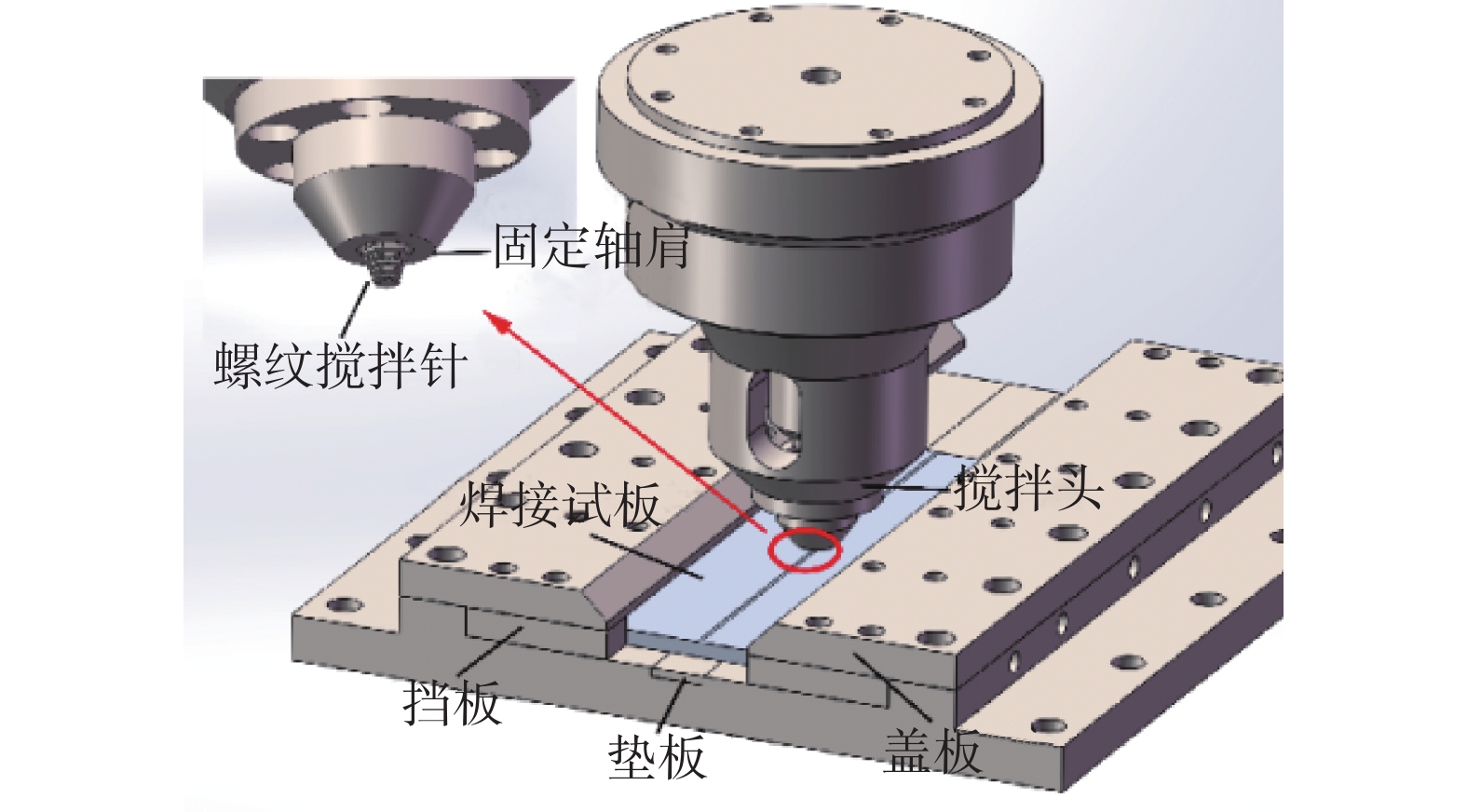
图 2 SSFSW工艺示意图及试样切割位置
Figure 2. Schematic diagram of SSFSW process and cutting positions of specimens
![]()
图 3 焊缝表面和接头截面宏观形貌
Figure 3. Weld surface and Macroscopic of cross-sections of SSFSW joints. (a) 500 r/min; (b) 600 r/min; (c) 700 r/min; (d) 800 r/min; (e) 1 000 r/min
![]()
图 5 SSFSW接头典型宏观形貌以及不同区域的显微组织
Figure 5. Typical macrostructure of SSFSW joint and microstructure of different areas. (a) Typical macrostructure; (b) BM; (c) top of WNZ; (d) middle of WNZ; (e) bottom of WNZ; (f) AS-TMAZ; (g) RS-TMAZ; (h) AS-HAZ; (i) RS-HAZ.
![]()
图 6 顶部晶粒尺寸
Figure 6. The grain size of the top WNZ. (a) 500 r/min; (b) 600 r/min; (c) 700 r/min; (d) 800 r/min; (e) 1 000 r/min
![]()
图 7 中部晶粒尺寸
Figure 7. The grain size of the middle WNZ. (a) 500 r/min; (b) 600 r/min; (c) 700 r/min; (d) 800 r/min; (e) 1 000 r/min
![]()
图 8 底部晶粒尺寸
Figure 8. The grain size of the bottom WNZ. (a) 500 r/min; (b) 600 r/min; (c) 700 r/min; (d) 800 r/min; (e) 1 000 r/min
![]()
图 11 700 r/min接头截面显微硬度分布
Figure 11. Cross-sectional hardness profiles of joints at 700 r/min
![]()
图 12 不同转速下WNZ硬度值分布
Figure 12. Microhardness distributions in WNZ at different rotational speed. (a) Microhardness distributions of the top WNZ; (b) Microhardness distributions of the middle WNZ; (c) Microhardness distributions of the bottom WNZ; (d) Microhardness distributions along WNZ thickness direction
![]()
图 14 BM和SSFSW接头的拉伸性能
Figure 14. Tensile properties of BM and SSFSW joints. (a) True stress-strain curve; (b) Tensile properties of BM and SSFSW joints
![]()
图 18 断口不同区域SEM图像
Figure 18. SEM images of different areas of fracture. (a) 600 r/min; (b) 700 r/min; (c) 800 r/min; (d) 1000 r/min
表 1 AZ31B化学成分(质量分数,%)
Table 1 The chemical compositions of AZ31B
Al Zn Mn Si Fe Cu Ni Ca Mg 3.1 0.99 0.38 <0.08 <0.003 <0.01 <0.001 <0.04 余量  下载: 导出CSV
表 2 AZ31B物理性能
Table 2 Physical properties of AZ31B
抗拉强度Rm/MPa 屈服强度Rel/MPa 断后伸长率A50(%) 熔点T/℃ 热导率λ/W·(m−1·K−1) 硬度H/HV 256 156 14 650 155 52 ~ 59
下载: 导出CSV
表 3 不同转速下WNZ硬度值的平均值和方差
Table 3 Mean and variance of Microhardness distributions in WNZ at different rotational speed
转速w/(r·min−1) WNZ顶部 WNZ中部 WNZ底部 沿WNZ厚度方向 硬度平均值H/HV 方差 硬度平均值H/HV 方差 硬度平均值H/HV 方差 硬度平均值H/HV 方差 600 56.38 10.90 54.22 6.30 52.41 5.28 57.71 4.07 700 54.07 2.53 54.65 10.97 52.93 5.24 60.83 3.28 800 56.02 6.90 55.11 9.82 53.65 3.84 56.70 4.08 1 000 56.68 2.39 59.23 9.02 54.65 3.00 59.63 5.40
下载: 导出CSV
表 4 SSFSW接头和BM的拉伸性能
Table 4 Tensile properties of SSFSW joint and BM
转速w/(r·min−1) 抗拉强度Rm/MPa 屈服强度Rel/MPa 断后伸长率A(%) 强度系数B(%) 600 205 88 5.5 80.1 700 231 96 9.7 90.2 800 227 94 9.3 88.7 1000 227 93 8.9 88.7
下载: 导出CSV
-
[1] Xu R Z, Ni D R, Yang Q, et al. Pinless Friction Stir Spot Welding of Mg-3Al-1Zn Alloy with Zn Interlayer[J]. Journal of Materials Science & Technology, 2016, 32(1): 76 − 88.
[2] Liu F J. Microstructure, mechanical properties, and corrosion resistance of friction stir welded Mg-Al-Zn alloy thick plate joints[J]. Welding in the World, 2021, 65: 229 − 241. doi: 10.1007/s40194-020-01012-z
[3] 徐安莲. 镁合金搅拌摩擦焊接头的显微组织及力学性能[D]. 重庆: 重庆大学, 2016. Xu Anlian. Microstructure and mechanical properties of magnesium alloy friction stir welded joints[D]. Chongqing: Chongqing university, 2016.
[4] 车朋卫. 静轴肩搅拌摩擦焊的工艺及焊接接头性能研究[D]. 甘肃: 兰州理工大学, 2019. Che Pengwei. Study on stationary shoulder friction stir welding technology and joint properties[D]. Gansu: Lanzhou University of Technology, 2019.
[5] Li W Y, Niu P L, Yan S R, et al. Improving microstructural and tensile properties of AZ31B magnesium alloy joints by stationary shoulder friction stir welding[J]. Journal of Manufacturing Processes, 2018, 37: 159 − 167.
[6] Patel V, Li W Y, Wen Q, et al. Surface analysis of stationary shoulder friction stir processed AZ31B magnesium alloy[J]. Materials Science and Technology, 2019, 35(5): 628 − 631. doi: 10.1080/02670836.2019.1570692
[7] Patel V, Li W Y, Wen Q, et al. Homogeneous Grain Refinement and Ductility Enhancement in AZ31B Magnesium Alloy Using Friction Stir Processin[C]//Magnesium Technology 2019: Springer, 2019, 1: 83 − 87.
[8] Patel V, Li W Y, Liu X C, et al. Tailoring grain refinement through thickness in magnesium alloy via stationary shoulder friction stir processing and copper backing plate[J]. Materials Science and Engineering: A, 784: 1-10.
[9] Patel V, Li W Y, Xu Y X. Stationary shoulder tool in friction stir processing: a novel low heat input tooling system for magnesium alloy[J]. Advanced Manufacturing Processes, 2019, 34(2): 177 − 182.
[10] 马宗义, 商 乔, 倪丁瑞, 等. 镁合金搅拌摩擦焊接的研究现状与展望[J]. 金属学报, 2018, 54(11): 1597 − 1617. doi: 10.11900/0412.1961.2018.00392 Ma Zongyi, Shang Qiao, Ni Dingrui, et. al. Friction stirwelding of magnesium alloys: a review[J]. Acta Metallurgica Sinica, 2018, 54(11): 1597 − 1617. doi: 10.11900/0412.1961.2018.00392
[11] 杨素媛, 张保垒. 厚板AZ31镁合金搅拌摩擦焊焊接接头的组织与性能[J]. 焊接学报, 2009, 30(5): 1 − 4. doi: 10.3321/j.issn:0253-360X.2009.05.001 Yang Suyuan, Zhang Baolei. Microstructures and mechanical properties of thick AZ31 magnesium alloy welded joint by friction stir welding[J]. Thansactions of the China Welding Institution, 2009, 30(5): 1 − 4. doi: 10.3321/j.issn:0253-360X.2009.05.001
[12] Chowdhury S H, Chen D L, Bhole S D, et al. Friction Stir Welded AZ31 Magnesium Alloy: Microstructure, Texture, and Tensile Properties[J]. Metallurgical& Materials Transactions A, 2013, 44(1): 323 − 336.
[13] Wang Y N, Lee C J, Huang C C, et al. Influence from extrusion parameters on high strain rate and low temperature superplasticity of AZ series Mg-based alloys[C]//Materials Science Forum. 2003, 426(432): 2655-2660
[14] Chang C I, Lee C J, Huang J C, et al. Relationship between grain size and Zener–Holloman parameter during friction stir processing in AZ31 Mg alloys[J]. Scripta Materialia, 2004, 51: 509 − 514. doi: 10.1016/j.scriptamat.2004.05.043
[15] Arbegast W J, Hartley P J. Proceedings of the fifth international conference on trends in welding research[C]. Georgia, The fifth international conference, 1998.
[16] Watanabe H, Tsutsui H, Mukai T, et al. Grain size control of commercial wrought Mg-Al-Zn alloys utilizing dynamic recrystallization[J]. Materials transactions, 2001, 42(7): 1200 − 1205. doi: 10.2320/matertrans.42.1200
[17] Shang Q, Ni D R, Xue P, et al. Evolution of local texture and its effect on mechanical properties and fracture behavior of friction stir welded joint of extruded Mg-3Al-1Zn alloy[J]. Materials Characterization, 2017, 128: 14 − 22. doi: 10.1016/j.matchar.2017.03.018
[18] Park S, Sato Y S, Kokawa H. Effect of micro-texture on fracture location in friction stir weld of Mg alloy AZ61 during tensile test[J]. Scripta Materialia, 2003, 49(2): 161 − 166. doi: 10.1016/S1359-6462(03)00210-0
[19] Peng J, Zhang Z, Liu Z, et al. The effect of texture and grain size on improving the mechanical properties of Mg-Al-Zn alloys by friction stir processing[J]. Scientific Reports, 2018, 8(1): 4196. doi: 10.1038/s41598-018-22344-3
[20] Bruni C, Forcellese A, Gabrielli F, et al. Effect of the ω/v ratio and sheet thickness on mechanical properties of magnesium alloy FSWED joints[J]. International Journal of Material Forming, 2010, 3(1 Supplement): 1007 − 1010.
[21] Chowdhury S M, Chen D L, Bhole S D, et al. Tensile properties of a friction stir welded magnesium alloy: Effect of pin tool thread orientation and weld pitch[J]. Materials Science & Engineering A, 2010, 527(21-22): 6064 − 6075.
[22] Afrin N, Chen D L, Cao X, et al. Microstructure and tensile properties of friction stir welded AZ31B magnesium alloy[J]. Materials Science & Engineering A, 2008, 472(1-2): 179 − 186.
[23] Commin L, Dumont M, Masse J E, et al. Friction stir welding of AZ31 magnesium alloy rolled sheets: Influence of processing parameters[J]. Acta Materialia, 2009, 57(2): 326 − 334. doi: 10.1016/j.actamat.2008.09.011
[24] Shang Q, Ni D R, Xue P, et al. Improving joint performance of friction stir welded wrought Mg alloy by controlling non-uniform deformation behavior[J]. Materials Science and Engineering:A, 2017, A707: 426 − 434.
[25] Xin R L, Liu D J, Shu X G, et al. Influence of welding parameter on texture distribution and plastic deformation behavior of as-rolled AZ31 Mg alloys[J]. Journal of Alloys & Compounds An Interdisciplinary Journal of Materials Science & Solid State Chemistry & Physics, 2016, 670: 64 − 71.
[26] Luo J, Mei Z, Tian W, et al. Diminishing of work hardening in electroformed polycrystalline copper with nano-sized and uf-sized twins[J]. Materials Science and Engineering:A, 2006, 441(1-2): 282 − 290. doi: 10.1016/j.msea.2006.08.051
[27] Afrin N, Chen D L, Cao B X, et al. Strain hardening behavior of a friction stir welded magnesium alloy[J]. Scripta Materialia, 2007, 57(11): 1004 − 1007. doi: 10.1016/j.scriptamat.2007.08.001
[28] Fu R D, Ji H S, Li Y J, et al. Effect of weld conditions on microstructures and mechanical properties of friction stir welded joints on AZ31B magnesium alloys[J]. Science and Technology of Welding & Joining, 2012, 17: 174 − 180. doi: 10.1179/1362171811Y.0000000056
[29] Woo W, Choo H, Brown D W, et al. Texture variation and its influence on the tensile behavior of a friction-stir processed magnesium alloy[J]. Scripta Materialia, 2006, 54(11): 1859 − 1864. doi: 10.1016/j.scriptamat.2006.02.019
-
期刊类型引用(2)
1. 龚宝明,张杰,李海龙. 金属封装管壳随机振动失效分析及抗振优化. 天津大学学报(自然科学与工程技术版). 2025(02): 167-174 .  百度学术
百度学术
2. 周舟,柯自攀,何日吉,李伟明,何骁. 高端装备用电子装联技术的发展现状及未来展望. 航天制造技术. 2024(06): 69-75 . 百度学术
其他类型引用(2)


计量
- 文章访问数: 270
- HTML全文浏览量: 64
- PDF下载量: 48
- 被引次数: 4
