
Microstructure and properties of MAG and oscillating laser arc hybrid welded X80 steel
-
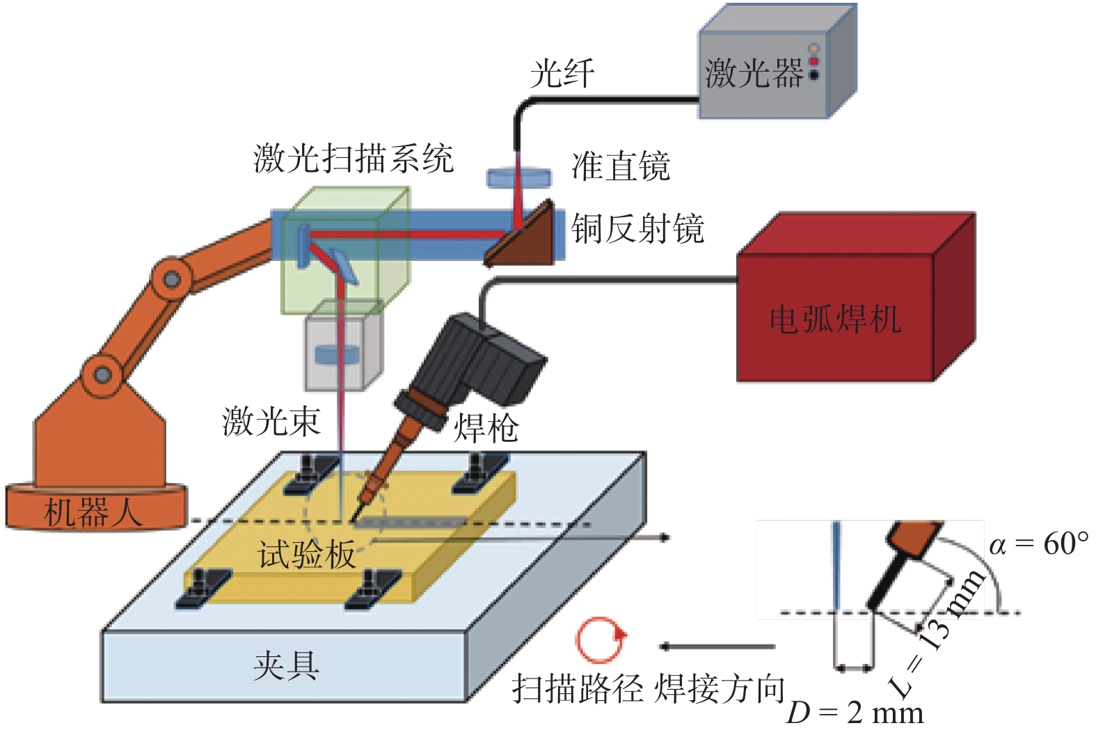
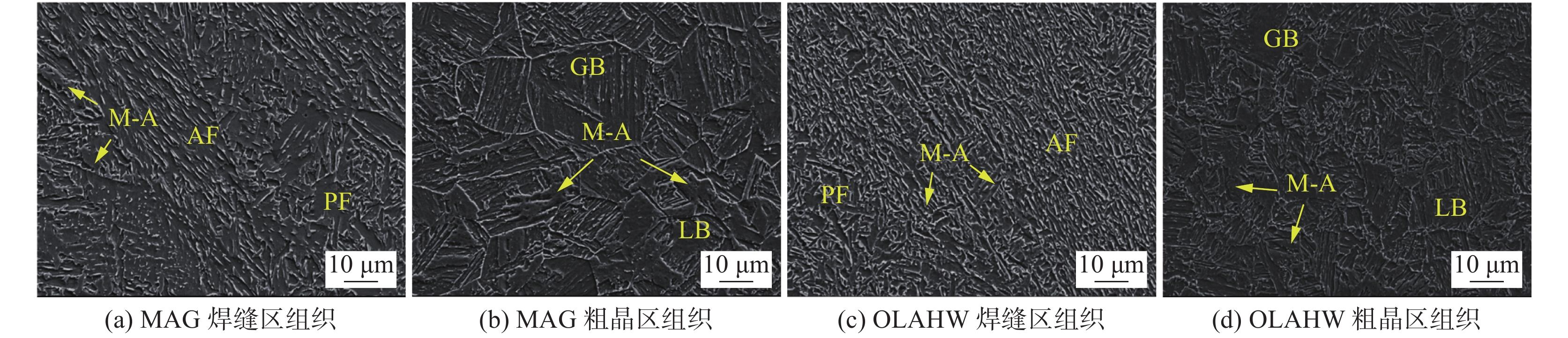
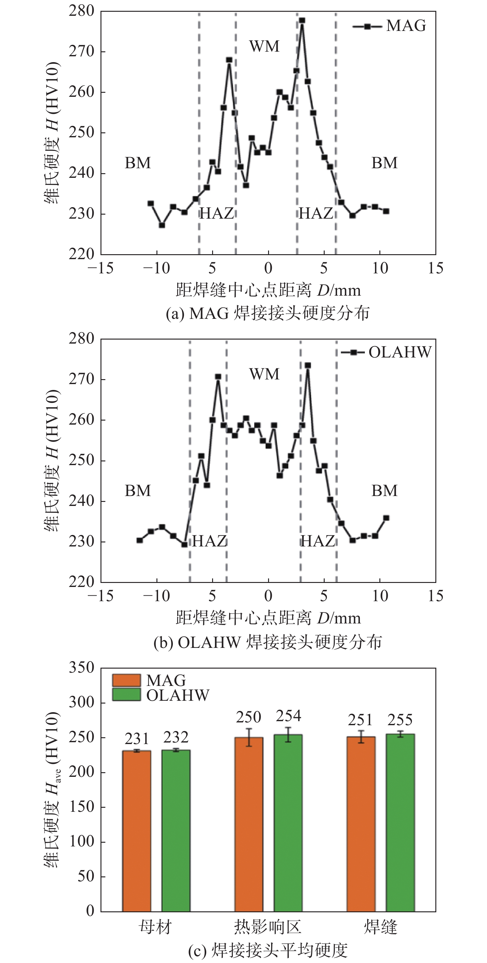
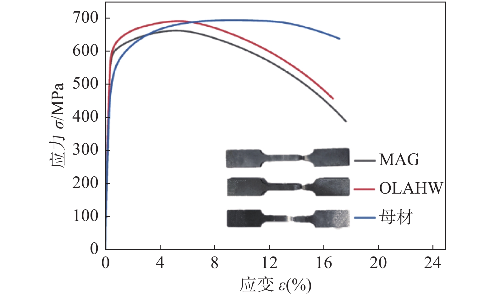
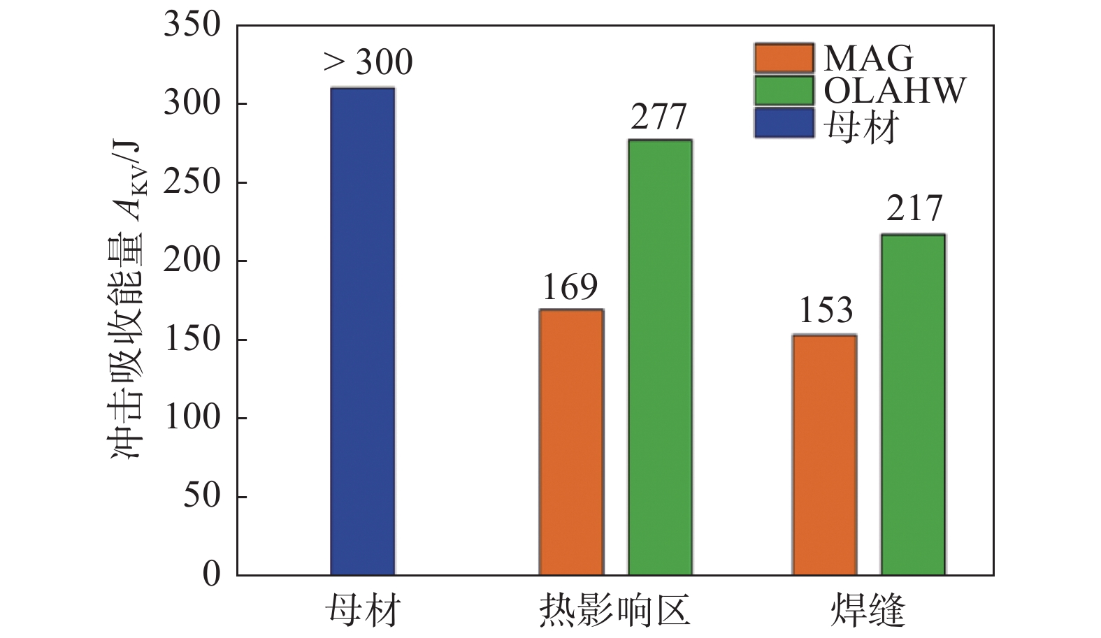
摘要: 在激光焊接打底情况下,对比研究了熔化极活性气体保护电弧焊(MAG)和激光扫描-电弧复合焊(OLAHW)工艺对X80管线钢接头成形、显微组织和力学性能(显微硬度、拉伸性能和冲击韧性)的影响规律. 结果表明,两种工艺下均能获得无气孔、夹渣和裂纹缺陷,成形良好的焊接接头,接头组织均主要由针状铁素体(AF)和M-A组元组成. 因为更小的焊接热输入和更快的冷却速度,以及激光束扫描促进形核作用,OLAHW填充接头组织中形成较MAG填充接头更多的针状铁素体和更细小的M-A组元. MAG和OLAHW两种填充工艺下接头平均显微硬度和拉伸强度接近,但OLAHW焊接接头的硬度变化相对MAG接头更平缓、硬度值波动较小,且OLAHW填充接头热影响区和焊缝区冲击吸收能量分别为277和217 J,较MAG填充接头分别提高了64%和42%.
-
关键词:
- X80管线钢 /
- MAG焊 /
- 激光扫描-电弧复合焊接 /
- 微观组织 /
- 冲击韧性
Abstract: Metal active gas welding (MAG) and oscillating laser arc hybrid welding (OLAHW) of X80 pipeline steel were carried out with backing weld by laser, the joint formation, microstructure and mechanical properties (microhardness, tensile properties and impact toughness) were studied. The results showed that sound joints without defects of pores, slag inclusion and crack were obtained by both the two processes. The joint microstructure was mainly composed of acicular ferrite (AF) and M-A components. Because of lower heat input, faster cooling rate and more nucleation sites promoted by the oscillated laser, more acicular ferrite and finer M-A components were formed within the OLAHW filled joints than those within MAG filled joints. The average microhardness and tensile strength of the joints obtained by the two filling processes were almost the same, but the hardness variation of OLAHW joints is gentler with less fluctuation. The impact energy of heat affected zone and weld zone of OLAHW filled joints were 277 and 217 J respectively, which is 64% and 42% higher than those of MAG filled joints. -
0. 序 言
随着国内海洋工程装备的快速发展,海洋平台的建设也逐渐向大型化的方向发展,所需要的钢板厚度日益增加,建造效率也随之加大. 为了提高焊接生产效率,大热输入焊接技术应运而生[1-2],气电立焊、电渣焊、单面埋弧焊等具有高效、安全可靠、便于自动化等优势的焊接技术得到越来越广泛的使用[3].
在大热输入焊接条件下,焊接热影响区(HAZ)的峰值温度将达到1 350 ℃,减慢了冷却速度,增加了原奥氏体晶粒长大时间,导致热影响区粗晶区的组织将急剧粗化,最终对焊接接头的韧性产生不利的影响[4-8]. 其中,奥氏体晶粒长大及相变规律与焊接热影响区的最终组织以及焊接接头冲击性能密切相关,因此,对奥氏体晶粒长大及相变规律的研究将有助于控制相变后的组织,进而提高冲击性能[9].
针状铁素体(IAF)是在低碳微合金钢的焊接热影响区组织中发现的,其大角度晶界的特点能有效阻碍钢中裂纹的扩展,提高钢的强度和韧性. 已有研究表明,不同种类的合金元素和夹杂物及其尺寸是影响焊接HAZ中IAF形核长大的主要因素,添加适当合金元素后形成的夹杂物,可以诱导IAF形核[10]. 对于低合金高强度钢,在大热输入焊接条件下,只有在0.2 ~ 20 μm范围内的夹杂物才可能作为有效的形核核心. 此外,IAF形核还与奥氏体晶粒的尺寸有关,但是对于不同的钢种,其利于IAF形核的最佳奥氏体晶粒尺寸也有所不同[11-13].
目前大热输入焊接条件下TiNbV微合金钢的焊接HAZ奥氏体晶粒尺寸与IAF形核之间关系的规律研究缺乏,使得焊接工艺设计缺乏理论依据. 付魁军等人[14]利用热模拟技术研究了在焊接热输入下TiNb钢热影响区组织变化对韧性的影响规律,但是对晶粒的生长及相变过程仍缺乏认识.
文中利用高温共聚焦显微镜原位观察方法研究奥氏体晶粒长大及相变规律,以期为大热输入钢的研发及应用提供理论依据.
1. 试验方法
试验用钢为中试厂冶炼试验的大热输入TiNbV钢,其化学成分及力学性能分别如表1和表2所示.
表 1 试验用钢化学成分(质量分数,%)Table 1. Chemical composition of the steel plateC Si Mn P S Ni Nb Al Ti N 0.079 0.2 1.45 0.003 6 0.001 5 0.16 0.021 0.018 0.016 0.005 6 表 2 试验用钢力学性能Table 2. Mechanical properties of the steel plate屈服强度ReH/MPa 抗拉强度Rm/MPa 断后伸长率A(%) −40 ℃冲击吸收能量 AKV/J 435 522 28 310 采用型号为VL2000DX-SVF17sp激光共聚焦显微镜对奥氏体晶粒长大及相变过程进行原位动态观察,可实现最快120桢/s的高速扫描. 加热采用1.5 kW卤素光源红外反射集光,可形成圆柱型超高温加热空间. 将试验用钢加工成ϕ7 mm × 3 mm(3 mm为板纵向方向)的圆片试样,上下表面用磨床磨平(绝对水平),柱面无明显划痕. 试样经180,200及500目金相砂纸打磨后进行抛光,用酒精冲洗并吹干备用. 把试样放置于显微镜加热台上. 为了更加清晰的观察奥氏体晶粒长大过程以及奥氏体晶粒尺寸对冷却过程中相变的影响,采用的热循环工艺为:以5 ℃/s的速度加热试样至1 400 ℃,分别保温5,100,300 s,然后以5 ℃/s的速度降温.
在试验过程中随机取20个奥氏体晶粒尺寸不再变化的视场,采用截点法统计其晶粒尺寸. 观察冷却过程中的相变,找出IAF的转变的起止温度,计算IAF转变的温度区间. 原位观察试验完成后,对试样进行重新抛光,用4%的硝酸酒精溶液腐蚀10 s后,在型号为VHX-1000E的金相显微镜下观察不同保温时间条件下,试样的最终金相组织.
2. 试验结果与分析
2.1 奥氏体晶粒长大过程
图1为热循环过程特征温度点奥氏体晶粒原位拍摄的形貌,对应的高温停留时间为5 s. 从图1可以看出,在升温阶段,约1 100 ~ 1 300 ℃时,晶粒开始发生明显的长大;约1 300 ~ 1 400 ℃晶粒迅速长大,晶粒大小趋于均匀. 在降温阶段,约1 400 ~ 1 300 ℃时,晶粒仍有长大趋势;当温度低于1 300 ℃,晶粒长大不明显.
![]() 图 1 热循环升温与降温阶段的奥氏体晶粒形貌Figure 1. Austenite grain morphology during heating and cooling stages of thermal cycle. (a) 1 100 ℃; (b) 1 200 ℃; (c) 1 350 ℃; (d) 1 400 ℃; (e) 1 300 ℃; (f) 1 100 ℃
图 1 热循环升温与降温阶段的奥氏体晶粒形貌Figure 1. Austenite grain morphology during heating and cooling stages of thermal cycle. (a) 1 100 ℃; (b) 1 200 ℃; (c) 1 350 ℃; (d) 1 400 ℃; (e) 1 300 ℃; (f) 1 100 ℃热循环升温与降温阶段晶粒尺寸的变化如图2所示. 从图中可以看出,温度低于1 250 ℃时,晶粒尺寸变化不明显,低于15 μm;当温度超过1 250 ℃时,晶粒尺寸开始发生明显的长大,加热到1 300 ~1 400 ℃阶段,晶粒尺寸从30 μm迅速长大至约60 μm.
![]() 图 2 热循环升温与降温阶段晶粒尺寸Figure 2. Grain size during heating and cooling stages of thermal cycle
图 2 热循环升温与降温阶段晶粒尺寸Figure 2. Grain size during heating and cooling stages of thermal cycle2.2 奥氏体晶粒长大方式
文中观察到两种晶粒长大方式:几个小晶粒合并成一个大晶粒的长大方式(图3)和晶界移动长大方式(图4). 几个小晶粒合并成一个大晶粒的长大方式,主要发生在加热升温过程的1 300 ~ 1 400 ℃高温区,该阶段温度较高,晶粒长大的驱动力较大,能明显观察到小晶粒的晶界迅速消失,取而代之的是由几个小晶粒的轮廓构成的较大晶粒的晶界,该种晶粒长大方式使得晶粒迅速长大,晶粒尺寸可迅速增加几倍. 晶界移动的晶粒长大方式主要发生在冷却过程的高温阶段1 400 ~ 1 350 ℃温度区间内,该阶段的晶粒已经达到较大尺寸,晶粒长大的驱动力难以使小晶粒合并成一个大晶粒的方式长大,但可以明显观察到晶界缓慢的移动,在该种晶粒长大方式下,晶粒长大的速度很慢. 此外还可以观察到,即使冷却至1 300 ℃左右时,晶粒仍以这种方式长大,但长大速度十分缓慢.
![]() 图 3 晶粒合并长大方式Figure 3. Several small grains transform into a big grain. (a) before merging; (b) after merging
图 3 晶粒合并长大方式Figure 3. Several small grains transform into a big grain. (a) before merging; (b) after merging![]() 图 4 晶界移动长大方式Figure 4. Movement of grain boundary. (a) before migration; (b) after migration
图 4 晶界移动长大方式Figure 4. Movement of grain boundary. (a) before migration; (b) after migration2.3 加热冷却过程中的相变
图5为热循环的相变过程. 从图中可以看出,当加热升温到一定温度时,首先发生由铁素体和珠光体向奥氏体的转变,当温度相对较低时,转变很不均匀,随着温度的提高,铁素体和珠光体向奥氏体的转变加快,最后完全转变为奥氏体. 随着温度的进一步提高,奥氏体化逐渐达到均匀. 当冷却降温时,初期组织仍保持奥氏体形式,当降温到一定温度时,开始发生由奥氏体向贝氏体的转变,转变过程非常迅速,转变完成后,全部为贝氏体组成.
![]() 图 5 相变过程Figure 5. Phase transformation process. (a) 860 ℃; (b) 960 ℃;(c) 650 ℃; (d) 600 ℃
图 5 相变过程Figure 5. Phase transformation process. (a) 860 ℃; (b) 960 ℃;(c) 650 ℃; (d) 600 ℃2.4 高温停留时间对冷却过程中相变的影响
IAF转变的开始温度、终了温度变化趋势如图6所示. 从图6中可以看出,高温停留时间分别为5,100,300 s. 对应的最终奥氏体晶粒尺寸分别为76.66,129.6,191.65 μm,高温停留时间越长,奥氏体晶粒尺寸越大且长大速度逐渐降低. 这是由于随保温时间的增加,碳化物逐渐溶解并均匀化分布,使得奥氏体逐渐均匀化分布,且高温停留时间越长,溶解及均匀化速率越低,最终奥氏体形状与尺寸趋于稳定.
![]() 图 6 IAF形成温度、终了随高温停留时间变化趋势Figure 6. Trend of the formation and ending temperature of IAF with the change of high-temperature dwell time
图 6 IAF形成温度、终了随高温停留时间变化趋势Figure 6. Trend of the formation and ending temperature of IAF with the change of high-temperature dwell time从图6中还可以看出,延长高温停留时间,IAF开始形成的温度和形成终了的温度不断降低,形成温度区间不断减小. 这是由于IAF形核与奥氏体尺寸有关,当高温停留时间较短时(5 s),奥氏体晶界面积较大,IAF优先在晶界处形核. 随高温停留时间的延长,奥氏体尺寸增大,晶界总面积减少,阻碍了晶界铁素体的析出,而IAF在夹杂物上的形核析出比晶界铁素体的析出温度要低,因此,IAF终了温度随高温停留时间不断降低且降低趋势逐渐减小,IAF转变温度区间不断降低.
贝氏体转变的开始温度、终了温度变化趋势如图7所示. 从图7中可以看出,延长高温停留时间,贝氏体开始形成的温度和形成终了的温度不断降低,形成温度区间不断减小. 这是由于随高温停留时间的延长,奥氏体尺寸与组织趋于稳定,当温度降低时,稳定的奥氏体难以在较高温度发生向贝氏体的转变,导致贝氏体形成温度降低. 贝氏体转变开始后,奥氏体迅速向贝氏体转变,且温度越低,转变越迅速. 因此,贝氏体终了温度随高温停留时间不断降低且降低趋势逐渐减小,贝氏体转变温度区间不断降低.
![]() 图 7 贝氏体形成温度、终了温度随高温停留时间变化趋势Figure 7. Trend of the formation and ending temperature of bainite with the change of high-temperature dwell time
图 7 贝氏体形成温度、终了温度随高温停留时间变化趋势Figure 7. Trend of the formation and ending temperature of bainite with the change of high-temperature dwell time为了分析高温停留时间对冷却组织中IAF的含量的影响,对原位观察之后的试样进行了组织分析,其结果如图8所示. 从图8中可以看出,高温停留5 s时,冷却转变后的组织主要为多边形铁素体,贝氏体和IAF,组织相对细小且不均匀,铁素体分布不均匀. 高温停留100 s时,冷却转变的组织主要为先共析铁素体,贝氏体IAF,无多边形铁素体,其中贝氏体、含量降低,IAF含量有所增加,且铁素体晶粒明显长大,组织较为均匀. 高温停留300 s时,贝氏体含量显著降低,IAF含量降低,先共析铁素体较为粗大,组织更为均匀.
![]() 图 8 不同高温停留时间下的金相组织Figure 8. Metallographic structure under different holding time. (a) 5 s of holding time; (b) 100 s of holding time; (c) 300 s of holding time
图 8 不同高温停留时间下的金相组织Figure 8. Metallographic structure under different holding time. (a) 5 s of holding time; (b) 100 s of holding time; (c) 300 s of holding time2.5 热循环过程中晶粒长大与相变模型
热循环过程中晶粒长大及相变随温度变化的模型如图9所示. 从图中可以看出,升温阶段,860 ℃开始发生奥氏体转变; 980 ℃奥氏体转变基本完成,但奥氏体分布并不均匀且尺寸较小,1 300 ~ 1 400 ℃晶粒迅速长大,均匀分布;降温阶段,在冷却过程的高温阶段1 400 ℃下,晶粒仍有长大趋势,温度低于1 300 ℃后,晶粒长大不明显;降温到660 ~ 580 ℃发生贝氏体转变,组织中产生多边形铁素体和针状铁素体,随转变的完成,铁素体含量逐渐增多. 降温阶段,降温到660 ~ 580 ℃发生贝氏体转变,组织中产生多边形铁素体和针状铁素体,随转变的完成,铁素体含量逐渐增多,奥氏体晶粒的大小对贝氏体转变后的组织形貌有直接影响,奥氏体晶粒大小决定了贝氏体板条束的最大长度.
![]() 图 9 热循环过程中晶粒长大及相变随温度变化的模型Figure 9. Modeling of the growth and phase transformation of the grains in HAZ with the heating temperature during thermal cycling. (a) original structure; (b) austenitic transition begins at 860 °C; (c) austenitic transition ends at 980 °C; (d) rapid growth of austenite at 1 300 °C; (e) grains merge at 1 400 °C; (f) grains migrate at 1 300 °C; (g) bainite transition begins at 660 °C; (h) bainite transition ends at 580 °C
图 9 热循环过程中晶粒长大及相变随温度变化的模型Figure 9. Modeling of the growth and phase transformation of the grains in HAZ with the heating temperature during thermal cycling. (a) original structure; (b) austenitic transition begins at 860 °C; (c) austenitic transition ends at 980 °C; (d) rapid growth of austenite at 1 300 °C; (e) grains merge at 1 400 °C; (f) grains migrate at 1 300 °C; (g) bainite transition begins at 660 °C; (h) bainite transition ends at 580 °C3. 结论
(1) TiNbV钢在加热升温过程中,奥氏体晶粒的长大趋势呈现先明显后缓慢的规律,升温至1 100 ℃以上,奥氏体晶粒开始有明显长大的趋势;升温至1 300 ~ 1 400 ℃,晶粒主要以合并长大方式迅速长大. 在冷却降温过程中,约在1 400 ~ 1 350 ℃,奥氏体晶粒以晶界迁移方式长大,呈现缓慢趋势.
(2) TiNbV钢在焊接热循环过程中,发生了奥氏体和贝氏体转变,加热至860 ℃时,开始发生奥氏体转变,加热至980 ℃,奥氏体转变基本完成,冷却到660 ~ 580 ℃,发生贝氏体转变,奥氏体晶粒大小决定了贝氏体板条束的最大长度.
(3) 高温停留时间对相转变温度和组织具有一定程度的影响,高温停留延长,奥氏体晶粒尺寸增大,IAF与贝氏体形成、终了温度及温度区间均有降低,冷却组织中贝氏体含量降低,先共析铁素体含量增加,IAF含量先增加后减少,组织出现均匀粗化趋势. 当高温停留时间为100 s时,组织中出现大量IAF,将会获得较好的冲击韧性.
-
![]()
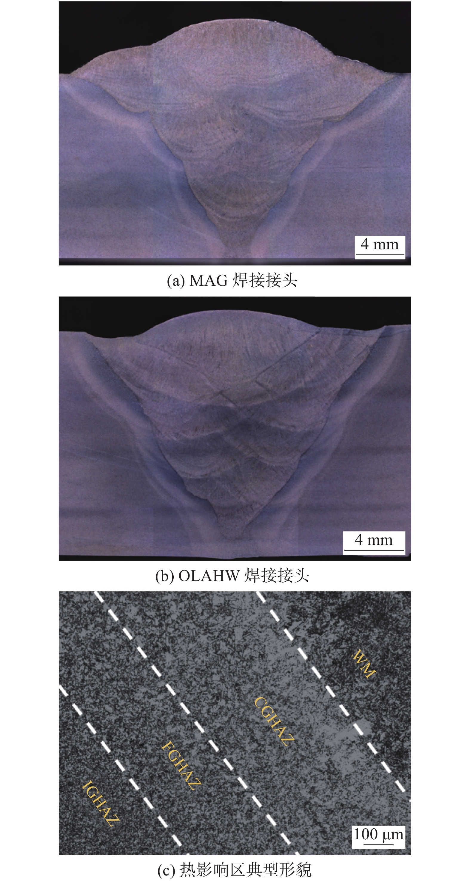
图 3 X80接头宏观形貌
Figure 3. Macro morphology of X80 joint. (a) MAG joint; (b) OLAHW joint; (c) typical morphology of heat affected zone
![]()
图 4 X80焊接接头显微组织
Figure 4. Microstructure of X80 welded joint. (a) microstructure of weld zone in MAG welding; (b) microstructure of coarse grain zone in MAG welding; (c) microstructure of weld zone in OLAHW welding; (d) microstructure of coarse grain zone in OLAHW welding
![]()
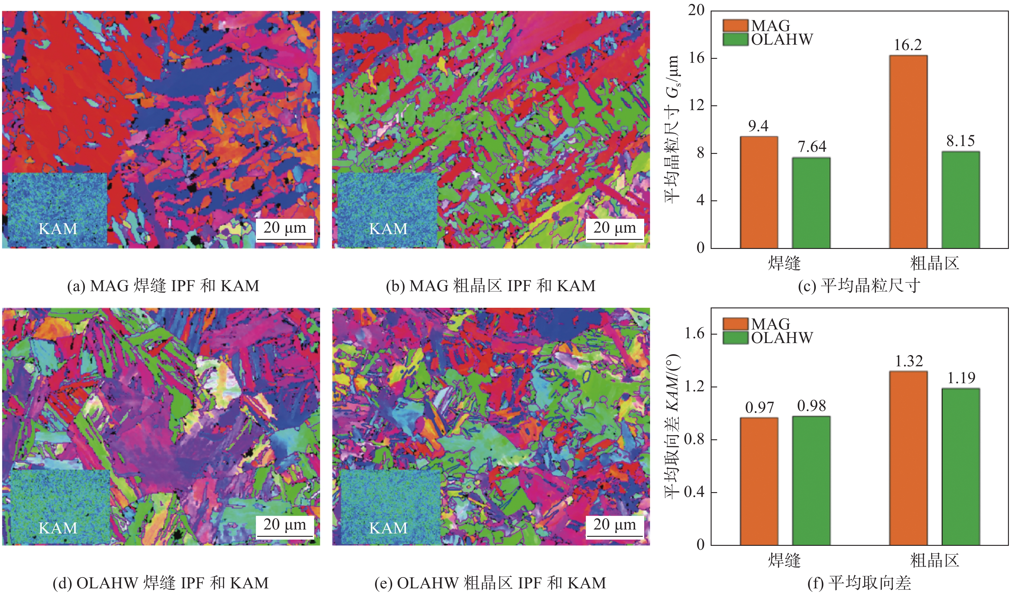
图 5 X80焊接接头EBSD结果
Figure 5. EBSD results of X80 welded joint. (a) IPF and KAM diagram of weld zone in MAG welding; (b) IPF and KAM diagram of coarse grain zone in MAG welding; (c) average grain size; (d) IPF and KAM diagram of weld zone in OLAHW welding; (e) IPF and KAM diagram of coarse grain zone in OLAHW welding; (f) average KAM value
![]()
图 6 X80焊接接头显微硬度
Figure 6. Microhardness of X80 welded joint. (a) hardness distribution of MAG welded joint; (b) hardness distribution of OLAHW welded joint; (c) average hardness of welded joint
![]()
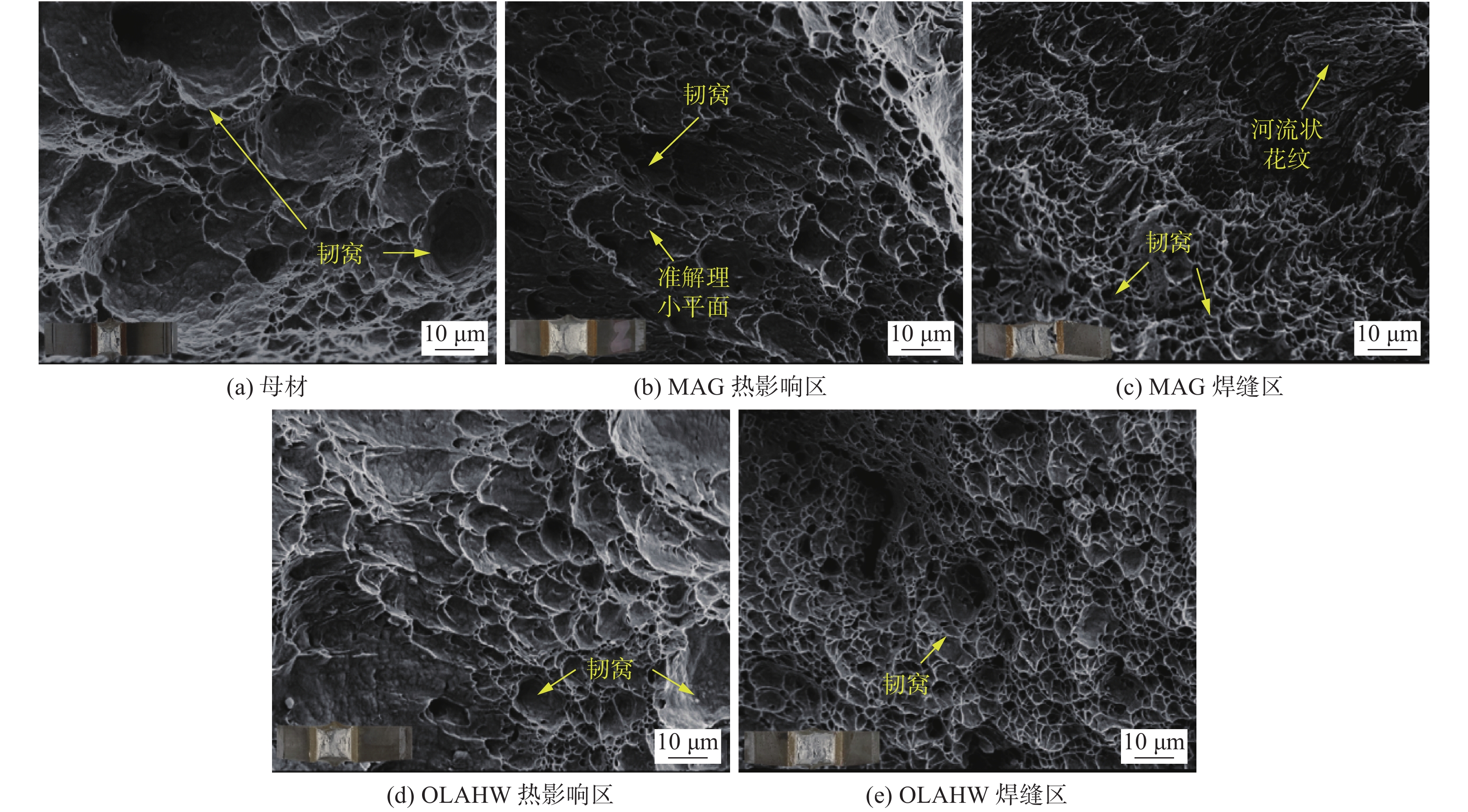
图 9 X80冲击断口微观形貌
Figure 9. Microstructure of X80 impact fracture. (a) base metal; (b) heat affected zone of MAG joint; (c) weld zone of MAG joint; (d) heat affected zone of OLAHW joint; (e) weld zone of OLAHW joint
表 1 母材和焊丝化学成分(质量分数,%)
Table 1 Chemical composition of base metal and welding wire
类别 C Si Mn Cu Cr Ni Mo Nb V Al Ti + Zr Fe X80 0.048 0.22 1.72 0.13 0.17 0.20 0.15 0.052 — 0.048 0.013 余量 JM-58 0.072 0.78 1.43 0.35 0.15 0.15 0.15 — 0.03 0.02 0.15 余量  下载: 导出CSV
表 2 MAG填充层焊接工艺参数
Table 2 Welding process parameters of MAG
焊接
次序焊接速度
v/(mm·s−1)送丝速度
vw/(m·min−1)焊枪摆动幅度
AM/mm焊枪摆动频率
fM/Hz2 10 5.0 1.5 10.0 3 ~ 5 5 7.0 2.0 8.0 6 ~ 8 5 8.0 3.0 8.0
下载: 导出CSV
表 3 OLAHW填充层焊接工艺参数
Table 3 Welding process parameters of OLAHW
焊接
次序激光功率
P/kW焊接速度
v/(mm·s−1)送丝速度
vw/(m·min−1)激光离焦量
∆f/mm2 1.0 10 4.0 + 25 3 1.0 10 7.0 0 4 ~ 7 1.5 10 8.0 0 8 ~ 10 1.5 8 8.0 0
下载: 导出CSV
-
[1] Devaney R J, Connaire A, O'Donoghue P E, et al. Process-structure-property fatigue characterisation for welding of X100 steel catenary risers[C]//International Conference on Offshore Mechanics and Arctic Engineering. American Society of Mechanical Engineers, 2019: V004T03A021.
[2] 周灿丰, 焦向东, 曹静, 等. 海洋深水立管环缝疲劳性能研究现状及建议[J]. 焊接, 2011(4): 5 − 10. Zhou Canfeng, Jiao Xiangdong, Cao Jing, et al. Research status and suggestions on circumferential seam fatigue performance of marine deepwater riser[J]. Welding & Joining, 2011(4): 5 − 10.
[3] Qiang B, Wang X. Ductile crack growth behaviors at different locations of a weld joint for an X80 pipeline steel: A numerical investigation using GTN models[J]. Engineering Fracture Mechanics, 2019, 213: 264 − 279. doi: 10.1016/j.engfracmech.2019.04.009
[4] Yang Y H, Shi L, Xu Z, et al. Fracture toughness of the materials in welded joint of X80 pipeline steel[J]. Engineering Fracture Mechanics, 2015, 148: 337 − 349. doi: 10.1016/j.engfracmech.2015.07.061
[5] 徐凯. X80焊管焊接接头疲劳性能的综合性研究[D]. 秦皇岛: 燕山大学, 2020. Xu Kai. Comprehensive study on fatigue properties of welded joints of X80 welded pipe[D]. Qinhuangdao: Yanshan University, 2020.
[6] Yang M, Liu Y, Zhang J, et al. Hybrid laser-arc welding of X90 pipeline steel: Effect of laser power on microstructure and mechanical properties[J]. Transactions of the Indian Institute of Metals, 2018, 71(10): 2487 − 2496. doi: 10.1007/s12666-018-1379-8
[7] Huang H, Zhang P, Yan H, et al. Research on weld formation mechanism of laser-MIG arc hybrid welding with butt gap[J]. Optics & Laser Technology, 2021, 133: 1 − 13.
[8] 严春妍, 张浩, 朱子江, 等. X80管线钢多道激光-MIG复合焊残余应力分析[J]. 焊接学报, 2021, 42(9): 28 − 34. Yan Chunyan, Zhang Hao, Zhu Zijiang, et al. Residual stress analysis of X80 pipeline steel by multi pass laser MIG hybrid welding[J]. Transactions of the China Welding Institution, 2021, 42(9): 28 − 34.
[9] Ivan B, Jan F, Akselsen O M, et al. The penetration efficiency of thick plate laser-arc hybrid welding[J]. The International Journal of Advanced Manufacturing Technology, 2018, 97: 2907 − 2919. doi: 10.1007/s00170-018-2103-x
[10] 黄瑞生, 杨义成, 蒋宝, 等. 超高功率激光-电弧复合焊接特性分析[J]. 焊接学报, 2019, 40(12): 73 − 77. Huang Ruisheng, Yang Yicheng, Jiang Bao, et al. Characteristic analysis of ultra high power laser arc hybrid welding[J]. Transactions of the China Welding Institution, 2019, 40(12): 73 − 77.
[11] 石庭深, 朱加雷, 焦向东, 等. X80管线钢激光-电弧复合焊接工艺[J]. 电焊机, 2015, 45(5): 69 − 72. Shi Tingshen, Zhu Jialei, Jiao Xiangdong, et al. Laser arc hybrid welding process of X80 pipeline steel[J]. Electric Welding Machine, 2015, 45(5): 69 − 72.
[12] Yin L, Wang J, Chen X, et al. Microstructures and their distribution within HAZ of X80 pipeline steel welded using hybrid laser-MIG welding[J]. Welding in the World, 2018, 62: 721 − 727. doi: 10.1007/s40194-018-0582-x
[13] 刘博, 王媛媛, 李彬. X120管线钢激光-电弧复合焊接头组织及硬度分析[J]. 焊管, 2021, 44(10): 19 − 23. Liu Bo, Wang Yuanyuan, Li Bin. Microstructure and hardness analysis of laser arc composite welded joint of X120 pipeline steel[J]. Welded Pipe and Tube, 2021, 44(10): 19 − 23.
[14] 王小朋. 不锈钢纯Ar保护激光扫描-CMT复合焊接研究[D]. 北京: 机械科学研究总院, 2012. Wang Xiaopeng. Study on laser scanning CMT hybrid welding of stainless steel with pure Ar protection[D]. Beijing: General Institute of Mechanical Sciences, 2012.
[15] Müller A, Goecke S F, Rethmeier M. Laser beam oscillation welding for automotive applications[J]. Welding in the World, 2018, 62: 1039 − 1047. doi: 10.1007/s40194-018-0625-3
[16] 许飞, 何恩光, 陈俐, 等. 钛合金扫描振镜激光-TIG复合焊接工艺研究[J]. 应用激光, 2020(5): 855 − 859. Xu Fei, He Enguang, Chen Li, et al. Study on laser TIG hybrid welding process of titanium alloy scanning galvanometer[J]. Applied Laser, 2020(5): 855 − 859.
[17] Fetzer F, Sommer M, Weber R, et al. Reduction of pores by means of laser beam oscillation during remote welding of AlMgSi[J]. Optics and Lasers in Engineering, 2018, 108: 68 − 77. doi: 10.1016/j.optlaseng.2018.04.012
[18] Cai C, Li L, Tao W, et al. Effects of weaving laser on scanning laser-MAG hybrid welding characteristics of high-strength steel[J]. Science and Technology of Welding and Joining, 2017, 22(2): 104 − 109. doi: 10.1080/13621718.2016.1199126
[19] 陈新亚. 激光-MAG复合摆动焊的焊接特性研究[D]. 哈尔滨: 哈尔滨工业大学, 2014. Chen Xinya. Study on welding characteristics of laser MAG hybrid swing welding[D]. Harbin: Harbin Institute of Technology, 2014.
[20] Wang X N, Sun Q, Zheng Z, et al. Microstructure and fracture behavior of laser welded joints of DP steels with different heat inputs[J]. Materials Science & Engineering A, 2017, 699: 18 − 25.
[21] 王进. X80高强钢组织及焊接工艺研究[D]. 成都: 西南石油大学, 2014. Wang Jin. Study on microstructure and welding process of X80 high strength steel[D]. Chengdu: Southwest Petroleum University, 2014.
-
期刊类型引用(3)
1. 陈腾升,张莉芹,胡锋,童明伟,吉梅锋,胡磊. 镁处理对CGHAZ冲击韧性及裂纹扩展的影响. 钢铁. 2023(01): 141-152 .  百度学术
百度学术
2. 方乃文,郭二军,徐锴,尹立孟,黄瑞生,马一鸣,武鹏博. 钛合金激光填丝焊缝晶粒生长及相变原位观察. 中国有色金属学报. 2022(06): 1665-1672 . 百度学术
3. 闫涵,赵迪,祁同福,冷雪松,付魁军,胡奉雅. 元素Nb对TiNbV微合金钢CGHAZ组织与冲击韧性影响. 焊接学报. 2020(12): 33-37+99 . 本站查看
其他类型引用(2)


计量
- 文章访问数: 670
- HTML全文浏览量: 133
- PDF下载量: 81
- 被引次数: 5
