
Mechanism and elimination of hot cracks in laser additive manufacturing of NiFe based superalloy
-
摘要: 针对NiFe基高温合金增材制造过程易出现热裂纹的问题,开展该合金热裂纹形成机理的研究,提出通过层间温度控制以及粉末氮化的方法,降低NiFe基高温合金激光增材过程中的热裂纹敏感性. 结果表明,热裂纹的出现主要是由于元素偏析以及热应力所引发的,热裂纹位置大多在大角度晶界处,这是由于大角度晶界中能量较高,在冷却过程中,晶界内液膜的存贮时间较长,从而造成偏析加剧. 当层间温度较低,冷却速度加快,能够减少合金中有害碳化物的长大,降低了大角度晶界比例,从而抑制热裂纹的出现. 粉末预氮化通过预先将Ti, Nb等元素进行氮化,形成稳定氮化物,在抑制开裂敏感性元素偏析的同时增加了形核点,促进晶粒细化,从而降低该合金的热裂纹敏感性.Abstract: To solve the problem of hot cracking in laser additive manufacturing process of NiFe based superalloy, the formation mechanism of hot crack was investigated, and the method of interlayer temperature control and powder nitriding to reduce the sensitivity of hot crack was proposed in the laser additive process of NiFe based superalloy. The results show that the occurrence of hot crack is mainly caused by element segregation and thermal stress. Most of the hot cracks are located at the high angle grain boundary, which own higher grain boundary energy to extend existing time of liquid film in grain boundaries during the cooling process, so the obvious segregation phenomenon occurs. When the interlayer temperature is lower, the cooling rate is faster, which can reduce the growth of harmful carbides in the superalloy. The proportion of high angle grain boundary is reduced, and the probability of hot crack is reduced further. Another method is to form stable nitrides by pre-nitriding Ti, Nb elements in the powder, which inhibits element segregation, increases the nucleation points and promotes grain refinement, therefore, the hot crack sensitivity of the superalloy is decreased.
-
Keywords:
- NiFe based superalloy /
- additive manufacturing /
- hot crack /
- interlayer temperature /
- nitride powder
-
-
![]()
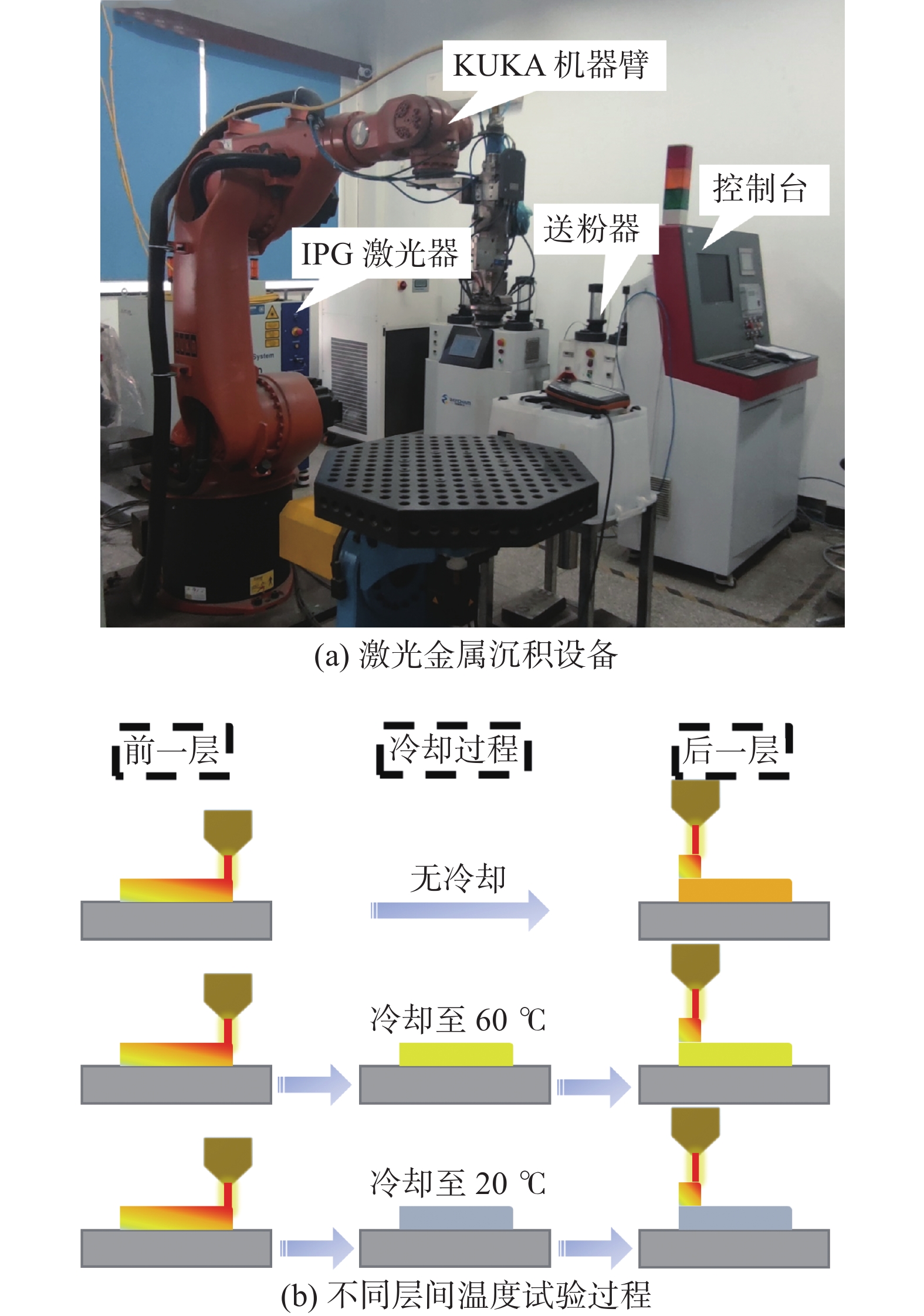
图 1 试验设备及试验过程
Figure 1. Experimental equipment and processes. (a) equipment of direct laser deposition; (b) experimental processes of different interlayer temperatures
![]()
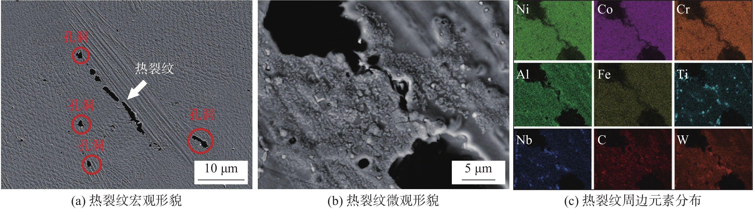
图 2 热裂纹形貌及元素分布
Figure 2. Microstructure and elements distribution of hot crack of S-120. (a) macroscopic morphology of hot crack; (b) microscopic morphology of hot crack; (c) distribution of elements around hot crack
![]()
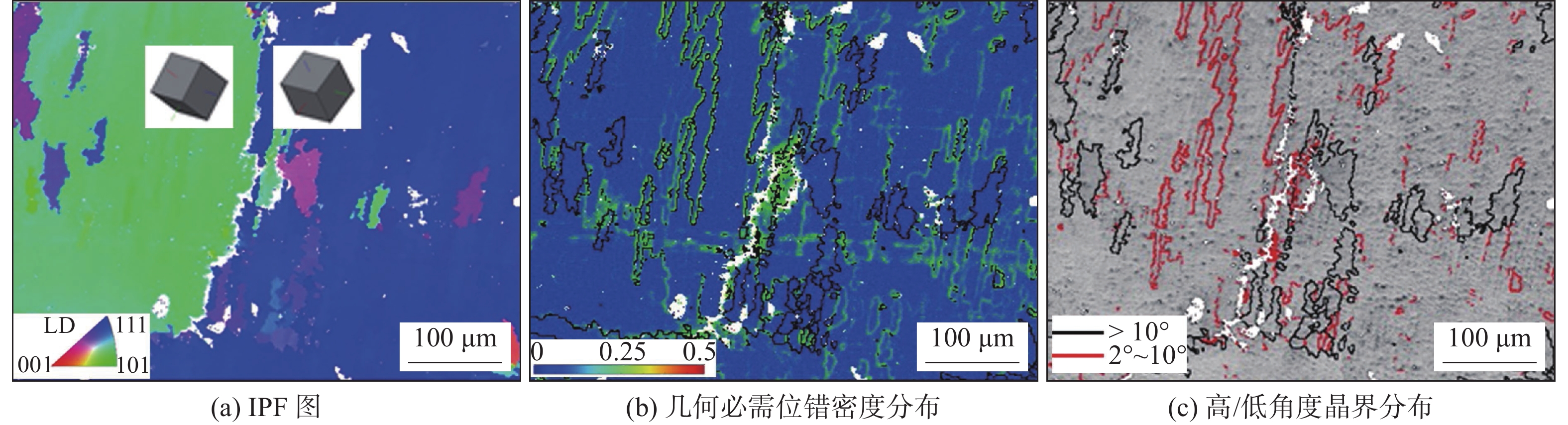
图 3 热裂纹周边EBSD结果
Figure 3. EBSD results around the hot crack. (a) IPF figure; (b) geometric necessary dislocation density distribution; (c) high/low angle grain boundary distribution
![]()
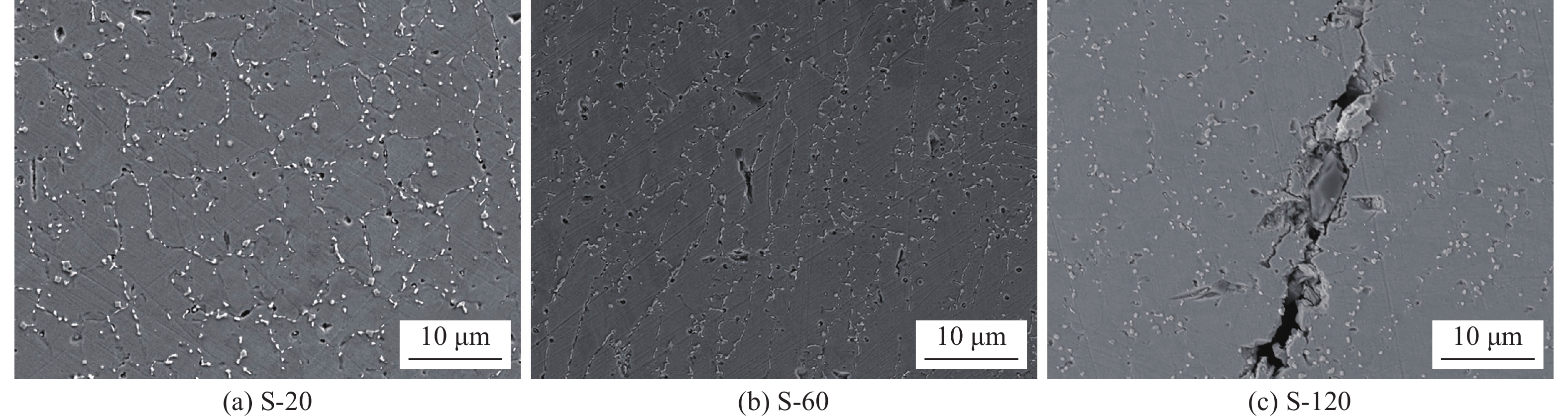
图 4 不同层间温度样品的微观组织
Figure 4. Microstructure of samples with different interlayer temperatures. (a) S-20; (b) S-60; (c) S-120
![]()
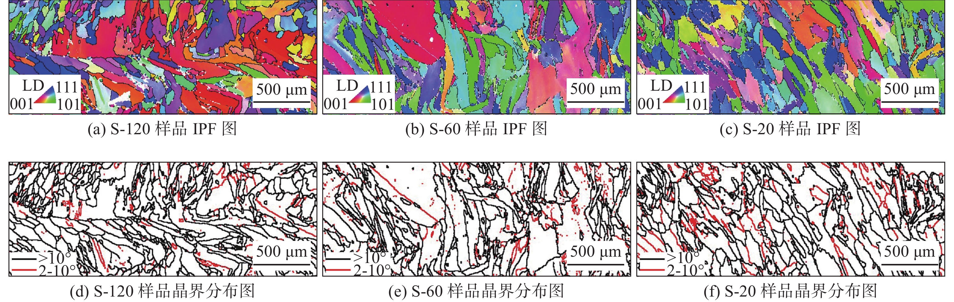
图 5 不同层间温度样品的微观取向
Figure 5. Micro orientations of samples at different interlayer temperatures. (a) IPF diagram of S-120; (b) IPF diagram of S-60; (c) IPF diagram of S-20; (d) grain boundary distribution of S-120; (e) grain boundary distribution of S-60; (f) grain boundary distribution of S-20
![]()
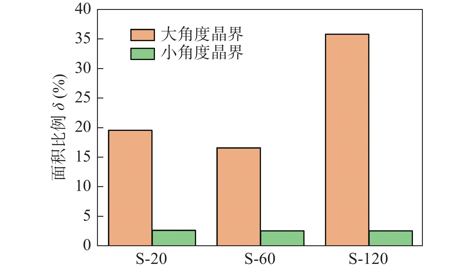
图 6 不同层间温度样品的大/小角度晶界比例
Figure 6. High/low angle grain boundary ratio of samples with different interlayer temperatures
![]()
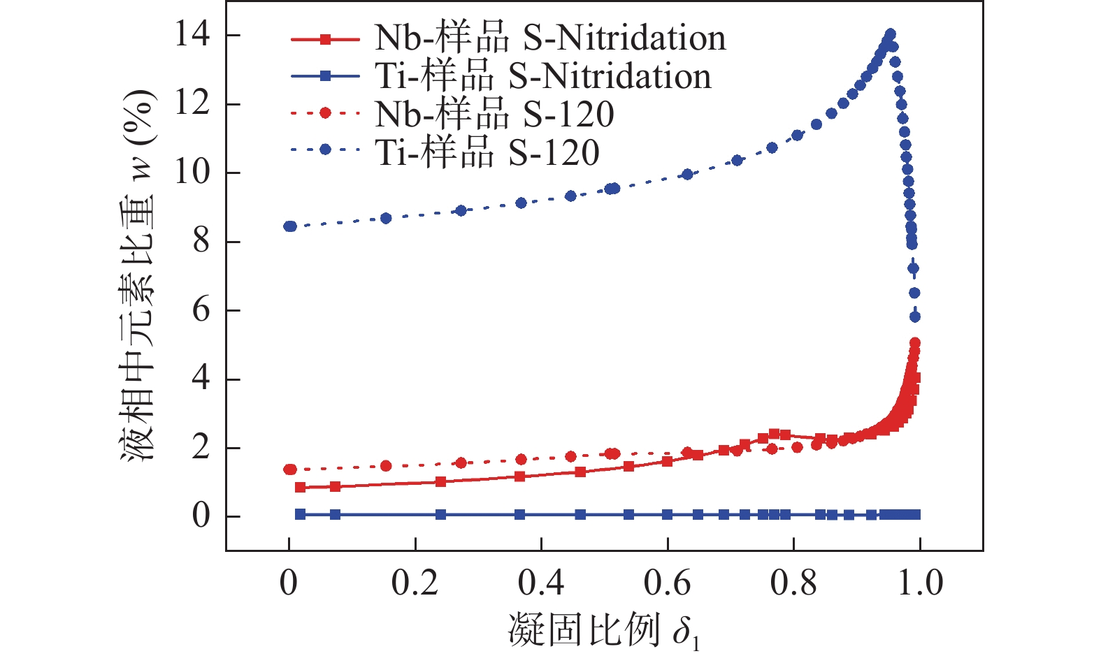
图 8 不同成分样品凝固过程中元素含量变化
Figure 8. Diagrams of element content during the solidification process of different samples
![]()
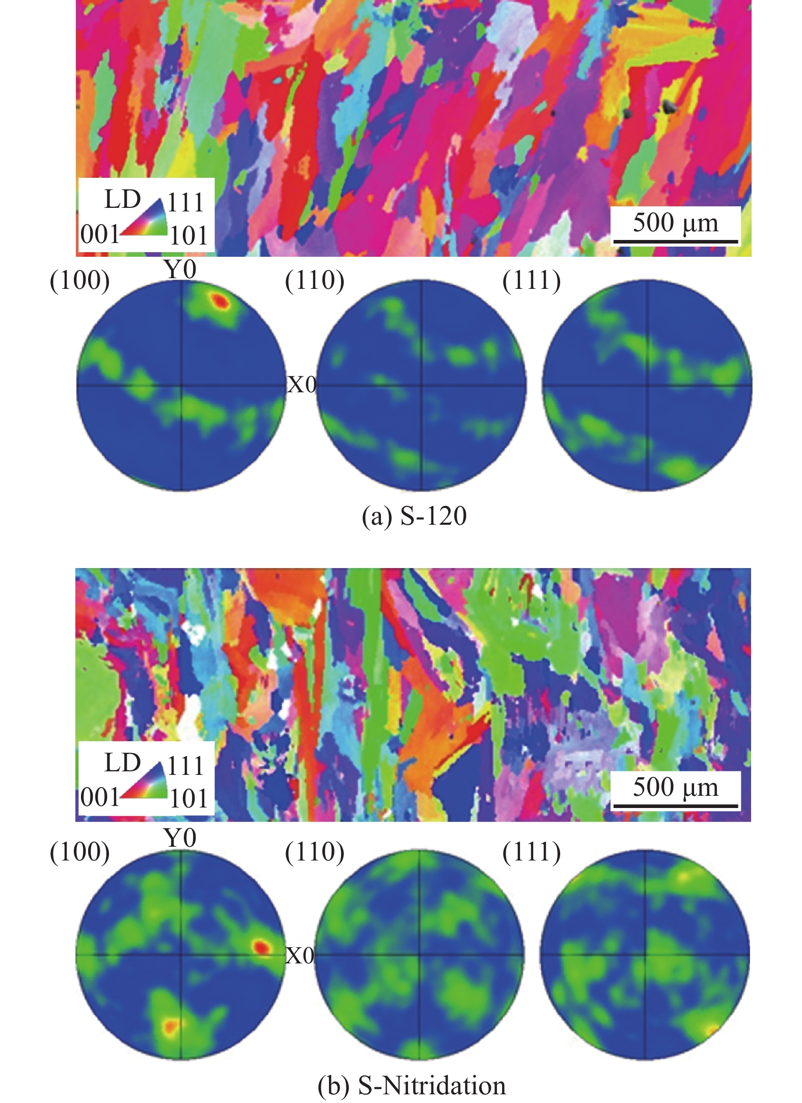
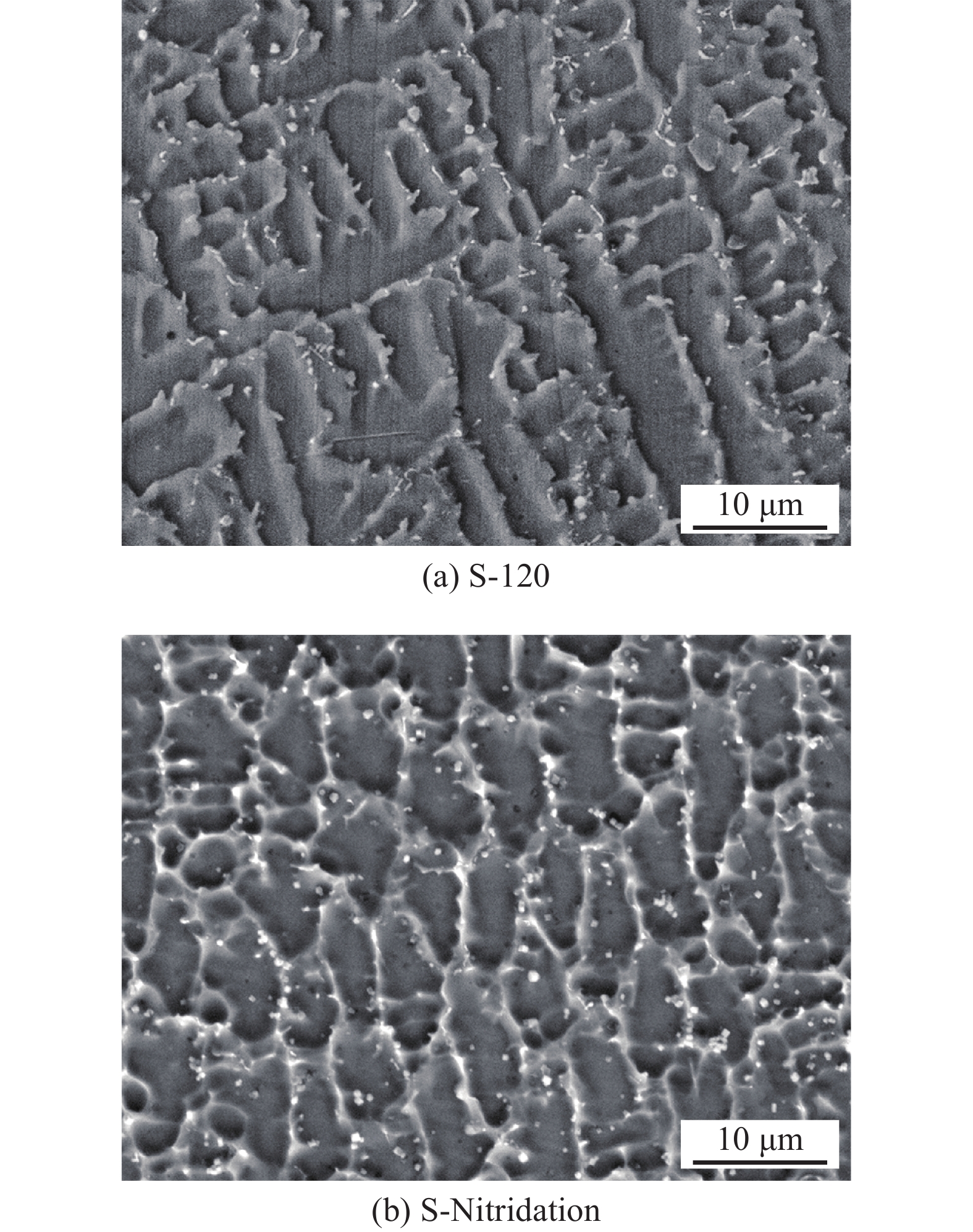
图 9 S-120样品以及S-Nitridation样品微观组织及取向
Figure 9. Microstructure and orientation of samples. (a) S-120; (b) S-Nitridation
表 1 NiFe基高温合金粉末成分(质量分数,%)
Table 1 Compositions of NiFe based superalloy powder
Ni Co Cr Fe Al Ti W Nb 38 25 20 5 3 0.5 8 0.5  下载: 导出CSV
表 2 激光金属沉积工艺参数
Table 2 Processing parameters of direct laser deposition
激光功率
P/W扫描速度
v/(mm·s−1)送粉量
Q/(g·min−1)保护气流量
q/(L·min−1)扫描间距
d/mm800 10 5 15 0.8
下载: 导出CSV
-
[1] Zhang P, Li J, Gong X, et al. Creep behavior and deformation mechanisms of a novel directionally solidified Ni-base superalloy at 900 °C[J]. Materials Characterization, 2019, 148: 201 − 207. doi: 10.1016/j.matchar.2018.12.023
[2] 袁勇, 党莹樱, 杨珍, 等. 700℃先进超超临界机组末级过热器用新型镍铁基高温合金的组织与性能[J]. 机械工程材料, 2020, 44(1): 44 − 50. doi: 10.11973/jxgccl202001008 Yuan Yong, Dang Yingying, Yang Zhen, et al. Microstructure and properties of Ni-Fe-base superalloy for 700 ℃ advanced ultra supercritical unit final superheater[J]. Materials for Mechanical Engineering, 2020, 44(1): 44 − 50. doi: 10.11973/jxgccl202001008
[3] Ostovari Moghaddam A, Shaburova N A, Samodurova M N, et al. Additive manufacturing of high entropy alloys: A practical review[J]. Journal of Materials Science & Technology, 2021, 77: 131 − 162.
[4] Lin D, Xu L, Li X, et al. A Si-containing FeCoCrNi high-entropy alloy with high strength and ductility synthesized in situ via selective laser melting[J]. Additive Manufacturing, 2020, 35: 101340. doi: 10.1016/j.addma.2020.101340
[5] Zheng M, Li C, Zhang X, et al. The influence of columnar to equiaxed transition on deformation behavior of FeCoCrNiMn high entropy alloy fabricated by laser-based directed energy deposition[J]. Additive Manufacturing, 2021, 37: 101660. doi: 10.1016/j.addma.2020.101660
[6] Griffiths S, Ghasemi H, Ivas T, et al. Combining alloy and process modification for micro-crack mitigation in an additively manufactured Ni-base superalloy[J]. Additive Manufacturing, 2020, 36: 101443. doi: 10.1016/j.addma.2020.101443
[7] Sun Z, Tan X, Wang C, et al. Reducing hot tearing by grain boundary segregation engineering in additive manufacturing: example of an AlxCoCrFeNi high-entropy alloy[J]. Acta Materialia, 2021, 204: 116505. doi: 10.1016/j.actamat.2020.116505
[8] Montero L, Liu Z, Bautmans L, et al. Effect of temperature on the microstructure and tensile properties of micro-crack free hastelloy X produced by selective laser melting[J]. Additive Manufacturing, 2020, 31: 100995. doi: 10.1016/j.addma.2019.100995
[9] 王爱华, 彭云, 肖红军, 等. 层间温度对690 MPa级HSLA钢熔敷金属裂纹扩展功的影响[J]. 焊接学报, 2012, 33(8): 65 − 68, 72. Wang Aihua, Peng Yun, Xiao Hongjun, et al. Effects of interpass temperature on crack propagation energy in deposited metal of 690 MPa grade HSLA steel[J]. Transactions of the China Welding Institution, 2012, 33(8): 65 − 68, 72.
[10] Liu P, Zhang R, Yuan Y, et al. Effects of nitrogen content on microstructures and tensile properties of a new Ni-Fe based wrought superalloy[J]. Materials Science and Engineering: A, 2021, 801: 140436. doi: 10.1016/j.msea.2020.140436
[11] 刘悦, 熊建坤, 赵海燕, 等. Hastelloy X和Haynes 230激光焊接头的组织性能[J]. 焊接学报, 2017, 38(8): 82 − 86. Liu Yue, Xiong Jiankun, Zhao Haiyan, et al. Microstructure of laser-welded Hastelloy X and laser-welded Haynes 230[J]. Transactions of the China Welding Institution, 2017, 38(8): 82 − 86.
[12] 冯伟, 徐锴, 郭枭, 等. 镍基丝极埋弧焊材料焊接热裂纹的分析与防止[J]. 焊接, 2016(8): 64 − 67, 76. doi: 10.3969/j.issn.1001-1382.2016.08.014 Feng Wei, Xu Kai, Guo Xiao, et al. Analysis and prevention of hot crack in nickel based submerged arc welding material welding[J]. Welding & Joining, 2016(8): 64 − 67, 76. doi: 10.3969/j.issn.1001-1382.2016.08.014
[13] Guo X, Liu S, Xu J, et al. Effect of step cooling process on microstructures and mechanical properties in thermal simulated CGHAZ of an ultra-high strength steel[J]. Materials Science and Engineering: A, 2021, 824: 141827. doi: 10.1016/j.msea.2021.141827
[14] Xu J, Wang S, Chai Z, et al. Comparison of the stress corrosion cracking behaviour of AISI 304 pipes welded by TIG and LBW[J]. Acta Metallurgica Sinica (English Letters), 2021, 34(4): 579 − 589. doi: 10.1007/s40195-020-01126-9
[15] 郭枭, 徐锴, 霍树斌, 等. 镍基合金焊丝GTAW熔敷金属凝固偏析行为[J]. 焊接学报, 2019, 40(7): 105 − 108. doi: 10.12073/j.hjxb.2019400190 Guo Xiao, Xu Kai, Huo Shubin, et al. Investigation on the solidification segregation behavior of GTAW nickel alloy deposited metal[J]. Transactions of the China Welding Institution, 2019, 40(7): 105 − 108. doi: 10.12073/j.hjxb.2019400190
[16] Zhao P, Fang K, Tang C, et al. Effect of interlayer cooling time on the temperature field of 5356-TIG wire arc additive manufacturing[J]. China Welding, 2021, 30(2): 17 − 24.
[17] Xu J, Lin X, Guo P, et al. The initiation and propagation mechanism of the overlapping zone cracking during laser solid forming of IN-738LC superalloy[J]. Journal of Alloys and Compounds, 2018, 749: 859 − 870. doi: 10.1016/j.jallcom.2018.03.366
计量
- 文章访问数: 831
- HTML全文浏览量: 79
- PDF下载量: 126
