
Forming mechanism and processing of stationary upper shoulder BT-FSW
-
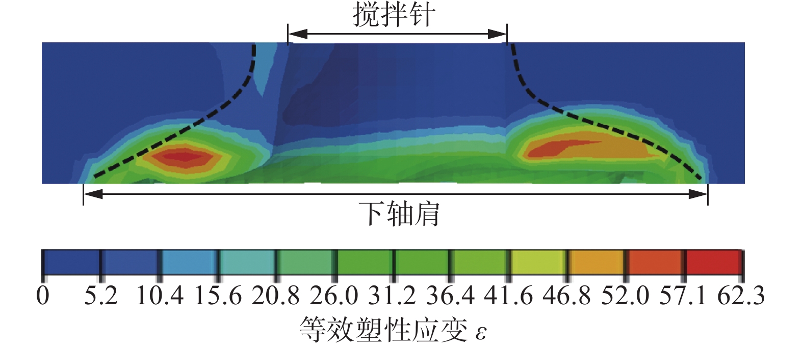
摘要: 以AA6056铝合金单静止上轴肩双轴肩搅拌摩擦焊(stationary upper shoulder bobbin tool friction stir welding,SSUBT-FSW)接头为研究对象,通过数值模拟与试验相结合的方法,阐明了SSUBT-FSW温度场与应变场分布规律及接头成形机理. 结果表明,SSUBT-FSW的上轴肩处于静止状态,有效增加了焊接稳定性,并将最大扭矩减小至55 N·m(常规双轴肩搅拌摩擦焊最大扭矩65 N·m). 静止上轴肩对焊缝表面施加顶锻压力,促使弧纹的波峰与波谷的高度差从60 μm减小至10 μm,显著提高了接头表面光洁度. 下轴肩旋转所产生的塑性应变区直径大于搅拌针,促使接头横截面等效塑性应变场呈梯形分布,与横截面温度场具有高度吻合性. SSUBT-FSW过程中产生材料非对称性流动行为,靠近下轴肩的材料流动性显著优于静止上轴肩.
-
关键词:
- 单静止上轴肩双轴肩搅拌摩擦焊 /
- 成形特征 /
- 温度场 /
- 材料流动
Abstract: Taking the stationary upper shoulder bobbin tool friction stir welding (SSUBT-FSW) welded joint of AA6056 aluminum alloy as the research object, the distributions of temperature and strain fields have been clarified based on combining with experimental and numerical simulation methods. Results show that the upper shoulder of SSUBT-FSW is in a static state, which effectively increases the welding stability and decreases the maximum torque to 55 N·m (the maximum torque of conventional bobbin tool friction stir welding is 65 N·m). The pressure of the stationary upper shoulder on the weld surface reduces the height difference between the peak and trough of the arc corrugations from 60 μm to 10 μm, which significantly improves the surface finish of the joint. The diameter of plastic strain zone driven by the lower rotating shoulder is larger than that developed by the probe, promoting the plastic strain field shows a trapezoidal shape on the cross section of the joint, which is good agreement with the shape of the temperature field. In the SSUBT-FSW process, the material flow of the lower shoulder is significantly better than that of the stationary upper shoulder, and the material asymmetry flow characteristics are formed along the thickness direction of the joint. -
0. 序言
随着船舶、海洋工程的大型化、轻量化发展,船舶用铝合金朝着轻质、高强方向发展.由于船舶材料服役环境复杂,对铝合金的强度、耐蚀性提出了更高要求. 5E61铝合金是在常规1561铝合金基础上加入Er元素,使其具有更高的强度和更好的耐蚀性能,是新一代船舶用高强高耐蚀铝合金[1-2]. 船舶用铝离不开配套的连接技术,目前针对5E61铝合金连接方面的研究主要集中在熔化焊,焊接方法主要采用最常见的非熔化极惰性气体保护焊(tungsten inert-gas welding,TIG焊)与熔化极惰性气体保护焊(melt inert-gas welding,MIG焊)[3-6]. 王虎等人[7]对新型Al-Mg-Mn-Er合金薄板进行TIG填丝焊接,研究焊接热输入对接头组织性能的影响,焊接系数最高可达71.4%. 闫德俊等人[8]采用双面双弧TIG焊方法对1561铝合金进行了焊接,发现焊缝区域存在特殊的组织不均匀性. 闫朝阳等人[9]采用穿孔等离子立焊方法对厚度为4 mm的5E61铝合金板材进行了焊接试验,焊接接头焊缝处硬度达到母材硬度的85%以上.
以上针对5E61铝合金的焊接主要集中在焊接工艺研究,对不同焊丝成分对焊缝组织及接头力学性能的影响未开展系统研究,国内外未见相关报道.因此,文中采用TIG焊方法,选用合金牌号为1561,5B71,5E61 3种成分焊丝(以下标记为Wire-1561,Wire-5B71,Wire-5E61),对4 mm厚5E61铝合金船板进行焊接,研究不同焊丝成分对焊缝组织和接头力学性能的影响,为船舶实际焊接作业及焊材选择提供理论依据.
1. 试验方法
试验所用基材为轧制5E61铝合金船板,规格为300 mm × 150 mm × 4 mm. 选用Wire-1561,Wire-5B71,Wire-5E61 3种合金牌号焊丝,焊丝直径均为1.2 mm. 5E61基材及3种焊丝化学成分如表1所示.
表 1 5E61基材及3种焊丝化学成分(质量分数,%)Table 1. Chemical compositions of 5E61 base material and three kinds of welding wire材料 Si Fe Cu Mn Mg Zn Zr Er Sc Al 5E61基材 0.15 0.12 0.01 0.91 5.91 0.01 0.12 0.19 — 余量 Wire-1561 0.05 0.08 0.02 0.94 5.69 0.01 0.08 — — 余量 Wire-5B71 0.03 0.11 0.01 0.01 6.02 0.02 0.12 — 0.34 余量 Wire-5E61 0.03 0.15 0.01 0.88 6.23 0.04 0.11 0.35 — 余量 采用Fronius Magic Wave TIG焊机进行焊接,接头形式为对接焊,板材间隙为1.2 mm,无需开坡口,单面焊双面成形. 试验前,用钢丝刷对基材进行打磨去除氧化膜,并用丙酮擦拭待焊区域,去除灰尘和油污等,以保证焊接质量. 焊接过程中采用工业纯氩(纯度不小于99%)作为保护气体保护焊接熔池,并根据大量试验获得较优的焊接工艺参数,如表2所示.
表 2 焊接工艺参数Table 2. Welding parameter氩气流量
Q/(L·min−1)焊接电流
I/A焊接速度
v/(m·min−1)板材间隙
d/mm12 170 ~ 180 0.18 1.2 采用Leica CH-9435型体式显微镜对焊缝表面及纵截面进行拍照,并利用image pro plus图形测试软件对焊缝几何尺寸进行测量统计. 采用AG-X Plus-10kN型万能试验机测试不同焊丝成分的TIG焊接头力学性能,拉伸试样垂直于焊缝方向,且焊缝的轴线位于试样平行段的中间,拉伸速度为1 mm/min,每组测试5个平行试样并取平均值. 采用Fisher HM 2000型显微硬度仪测量显微硬度,加载载荷为0.98 N,保载时间为15 s,由焊缝中心向两侧每隔1 mm取点测试.
对基材及焊接接头试样进行阳极覆膜,采用Axio Scope A1型光学显微镜进行微观组织观察.采用配有能谱仪(energy dispersive spectrometer,EDS) 和电子背散射衍射(electron backscattered diffraction,EBSD) 探头的TESCAN MIR3型场发射扫描电镜对拉伸断口形貌、第二相成分以及焊缝处晶粒组织进行分析. EBSD样品经打磨、机械抛光后,采用HClO4 + CH3OH (体积比为1∶9)的腐蚀液进行电解抛光. 采用Empyream型 X射线衍射仪(X-ray diffractomer,XRD)对5E61基材及焊接接头焊缝区进行物相分析.
2. 试验结果与分析
2.1 焊缝成形
图1为3组焊丝接头焊缝正、反面表面形貌. 从图1可以看出,在相同的焊接工艺下,3种焊丝形成的焊缝质量稳定,正面形成均匀细小的鱼鳞纹,反面熔深充分,形成水滴熔池,实现单面焊双面成形. 图2 为焊缝纵截面形貌及几何尺寸. 从图2a可以看出,焊缝成形优良,呈轴对称分布;中心处无明显的气孔缺陷,零星的微小气孔只存在焊缝表面. 将3组焊缝上熔宽、下熔宽、上余高和下余高进行测量统计,结果如图2b所示. 3种焊丝焊接接头几何尺寸接近,波动较小,说明焊接工艺稳定,焊缝成形质量好.
![]() 图 2 焊缝纵截面及几何参数Figure 2. Longitudinal section and geometry parameter of welding lines. (a) longitudinal section; (b) geometry parameter
图 2 焊缝纵截面及几何参数Figure 2. Longitudinal section and geometry parameter of welding lines. (a) longitudinal section; (b) geometry parameter2.2 焊接接头显微组织
图3 为5E61基材晶粒取向分布图及晶界统计分布图. 对原始5E61基材沿轧制方向进行EBSD观察,结果如图3a所示. 原始基材经冷轧后进行不完全退火,变形组织发生部分再结晶形成等轴组织;部分纤维组织发生合并长大变宽的情况,纤维组织出现分节,形成长径比约为4的再结晶晶粒;边界处的小晶粒数量增多. 由图3b可知,组织中仍存在大量的低角度晶界(2° ~ 15°代表低角度晶界,low angle grain boundaries,LAGBs;高于15°代表高角度晶界,high angle grain boundaries,HAGBs),占比59.8%,经过不完全退火后,板材组织保留部分轧制位错形成的亚晶界,该组织既能充分释放轧制过程材料的内应力,又保证了基材的力学性能.
![]() 图 3 5E61基材晶粒取向分布及晶界统计分布Figure 3. Grain orientation distribution map and grain boundary angle distributions map of 5E61 base material. (a) grain orientation distribution; (b) grain boundary angle distribution
图 3 5E61基材晶粒取向分布及晶界统计分布Figure 3. Grain orientation distribution map and grain boundary angle distributions map of 5E61 base material. (a) grain orientation distribution; (b) grain boundary angle distribution图4为不同焊丝焊接接头的金相覆膜组织. 可以看出,焊接接头分为焊缝区(welding zone,WZ)、熔合区(fusion zone,FZ)以及热影响区(heat affected zone,HAZ)3部分. 焊缝区呈现典型的铸造组织特征,中心位置呈等轴晶形貌. 在焊缝区与热影响区之间存在一定宽度的过渡区即熔合区,该区域晶粒具有明显的晶粒取向,从焊缝区指向热影响区,形成长条状组织,且尺寸不均匀. 3组接头熔合区宽度接近,从图中测出约为180 ~ 200 μm.
![]() 图 4 焊接接头的金相组织Figure 4. Microstructure of welded joints. (a) FZ of Wire-1561; (b) WZ of Wire-1561; (c) FZ of Wire-5B71; (d) WZ of Wire-5B71; (e) FZ of Wire-5E61; (f) WZ of Wire-5E61
图 4 焊接接头的金相组织Figure 4. Microstructure of welded joints. (a) FZ of Wire-1561; (b) WZ of Wire-1561; (c) FZ of Wire-5B71; (d) WZ of Wire-5B71; (e) FZ of Wire-5E61; (f) WZ of Wire-5E61图5为3种焊丝形成的焊接接头焊缝区及热影响区EBSD晶粒取向分布. 将各组接头的焊缝区及热影响区低角度晶界占比进行统计,结果如图6所示. 从图6可以看出,3组接头热影响区低角度晶界占比(ωLAGBs)较基材明显下降,均在35% ~ 38%范围内. 这是由于TIG焊高的热输入使得原基材未完全再结晶组织发生了二次退火,再结晶程度进一步提高,冷变形过程产生的位错等亚结构湮灭,晶界主要以高角度再结晶晶界形式存在. 从图5可以看出,不同焊丝接头焊缝区晶粒大小差异明显. 通过HKL Channel 5软件计算,Wire-1561接头晶粒最大,约为45 μm;Wire-5E61接头次之,约为26 μm;Wire-5B71接头晶粒尺寸最小,约为9 μm. 对比3组接头焊缝区ωLAGBs可以发现,Wire-5E61接头ωLAGBs最小,Wire-5B71接头次之,Wire-1561接头最大. 这是由于Wire-5E61中Mg元素含量最高,β(Mg2Al3)相数量较多,且焊丝中含有Er元素,焊后在焊缝区形成含Er弥散相,增加再结晶形核质点,使得Wire-5E61接头焊缝区晶粒细小,再结晶程度最高.
![]() 图 5 不同焊丝接头焊缝及热影响区的晶粒取向分布图Figure 5. Orientation distribution maps of WZ and HAZ of welded joints with different welding wires. (a) WZ of Wire-1561; (b) HAZ of Wire-1561; (c) WZ of Wire-5B71; (d) HAZ of Wire-5B71; (e) WZ of Wire-5E61; (f) HAZ of Wire-5E61
图 5 不同焊丝接头焊缝及热影响区的晶粒取向分布图Figure 5. Orientation distribution maps of WZ and HAZ of welded joints with different welding wires. (a) WZ of Wire-1561; (b) HAZ of Wire-1561; (c) WZ of Wire-5B71; (d) HAZ of Wire-5B71; (e) WZ of Wire-5E61; (f) HAZ of Wire-5E61![]() 图 6 不同焊丝接头焊缝及热影响区的低角度晶界占比Figure 6. Proportion of low angle grain boundaries in WZ and HAZ of welded joints with different welding wires
图 6 不同焊丝接头焊缝及热影响区的低角度晶界占比Figure 6. Proportion of low angle grain boundaries in WZ and HAZ of welded joints with different welding wires图7为5E61基材及3种焊丝接头焊缝区XRD图谱. 从图7可以看出,基材中除存在α-Al基体和β相(Mg2Al3)外,还含有少量Mg2Si,Al6Mn和Al-(Fe,Mn)-Si相,衍射峰明显;在Wire-1561接头焊缝区仅检测到Al-(Fe,Mn)-Si相和Al6Mn相的衍射峰,且强度较弱;由于Wire-5B71焊丝成分中几乎不含Si和Mn元素,在该焊缝区未检测到上述3种物相衍射峰;而在Wire-5E61接头焊缝区只检测到Al-(Fe,Mn)-Si的衍射峰. 另外,由于Sc,Er元素形成的析出相含量较少,X射线衍射无法检测标定.
![]() 图 7 5E61基材及不同焊丝接头焊缝区的XRD图谱Figure 7. XRD patterns of 5E61 base material and WZ of welded joints with different welding wires
图 7 5E61基材及不同焊丝接头焊缝区的XRD图谱Figure 7. XRD patterns of 5E61 base material and WZ of welded joints with different welding wires图8为5E61基材及3种焊丝接头焊缝区SEM形貌,并对图中P1 ~ P9点进行EDS成分分析,结果如表3所示. 5E61基材第二相尺寸均匀,主要为β相(Mg2Al3)和Al-(Fe,Mn)-Si相,尺寸在2 μm以下. 从表3可知,Wire-5E61接头焊缝区α-Al基体中Mg含量最高,Wire-5B71次之,Wire-1561 Mg含量最低(表3中P2,P5,P7点),可见TIG焊接工艺下焊缝区主要由焊丝成分决定,随着焊丝中Mg含量的提高,焊缝区α-Al基体中固溶的Mg含量随之提高. 从图8可以看出,α-Al基体中主要存在亮白色的β相(Mg2Al3),呈片状沿晶界析出,尺寸约为4 ~ 6 μm. 通过对比可以看出,Wire-5E61接头第二相比例最高,Wire-5B71接头次之,Wire-1561接头最低,其中Wire-1561焊丝接头焊缝区出现了一定程度的第二相聚集长大,这对焊缝区组织均匀性与焊缝力学性能不利. 图8d、图8f和图8h分别为3种焊丝接头焊缝区高倍SEM形貌,可以发现焊缝组织中存在着大量白色析出相. EDS测试结果显示,对于Wire-1561接头,析出相主要为Al6Mn;而对于Wire-5B71和Wire-5E61接头,析出相分别为初生Al3(Sc,Zr)和Al3(Er,Zr)[10-11].
表 3 EDS测试结果(质量分数,%)Table 3. Results of EDS tests位置 Al Mg Si Fe Mn Er Sc Zr 可能物相 P1 92.13 5.25 0.42 0.38 1.82 — — — α-铝基体 P2 77.48 2.84 3.51 7.40 8.77 — — — β相、Al-(Fe,Mn)-Si P3 87.78 5.32 — — 6.90 — — — β相、Al6Mn P4 83.27 5.07 — 3.64 8.02 — — — β相、Al6(Mn,Fe) P5 93.97 6.03 — — — — — — α-铝基体 P6 78.33 4.83 — 5.62 3.34 — 4.76 3.12 β相、Al3(Sc,Zr) P7 93.82 6.18 — — — — — — α-铝基体 P8 79.48 4.02 — 10.72 5.78 — — — β相、Al6(Mn,Fe) P9 67.43 4.40 — — 9.52 13.28 — 5.37 β相、Al3(Er,Zr) ![]() 图 8 不同焊丝接头焊缝区SEM形貌Figure 8. SEM morphology of WZ microstructure with different welding wires. (a) 5E61 base material; (b) image of the selected area A; (c) WZ of Wire-1561; (d) image of the selected area B; (e) WZ of Wire-5B71; (f) image of the selected area C; (g) WZ of Wire-5E61; (h) image of the selected area D
图 8 不同焊丝接头焊缝区SEM形貌Figure 8. SEM morphology of WZ microstructure with different welding wires. (a) 5E61 base material; (b) image of the selected area A; (c) WZ of Wire-1561; (d) image of the selected area B; (e) WZ of Wire-5B71; (f) image of the selected area C; (g) WZ of Wire-5E61; (h) image of the selected area D结合3种焊丝的合金成分,Wire-1561焊丝中Mn元素含量接近1%(0.94%),在非平衡凝固下从基体中析出Al6Mn;对于Wire-5B71和Wire-5E61两种焊丝,由于Sc和Er元素的添加,在焊丝凝固过程中均发生共晶反应,形成Al3(Sc,Zr)和Al3(Er,Zr)纳米粒子,实现充分的溶质原子析出,为后续焊缝凝固组织提供大量异质形核点,有效细化焊缝枝晶组织,抑制晶粒长大,达到焊缝区细晶强化的目的.
2.3 焊接接头力学性能
图9为3种焊丝成分下的焊接接头显微硬度分布. 3组接头的硬度分布变化趋势基本一致,均以焊缝中心为对称轴,呈对称分布.5E61基材显微硬度约为98 HV;在焊缝区,Wire-5E61焊丝接头平均显微硬度明显高于其余两组,约为91 HV. 这是由于Wire-5E61中Mg元素含量最高,在相同的TIG焊接工艺下,Mg元素的固溶程度最高,且焊丝中含有Er元素,形成大量均匀分布的Al3Er纳米析出相,提供大量异质形核质点,实现焊缝凝固组织的晶粒细化,在固溶强化和细晶强化的双重作用下,焊缝硬度最大. 3组接头均在熔合线位置达到硬度最小值,约为84 ~ 86 HV. 由于在相同的焊接工艺下焊接热输入一致,致使3组接头热影响区宽度基本一致,且热影响区硬度值接近.
5E61基材及不同成分焊丝下焊接接头的拉伸性能如表4所示. 5E61基材的抗拉强度、屈服强度和断后伸长率分别为386,218 MPa和18.0%. Wire-1561,Wire-5B71和Wire-5E61 3种焊丝接头的抗拉强度分别为322,323和338 MPa,屈服强度分别为175,173和177 MPa,断后伸长率分别为13.0%,14.5%和14.5%,焊接系数分别为0.83,0.84和0.88. 以上结果表明,Wire-5E61焊接接头力学性能最优,与焊缝处显微硬度一致.
表 4 5E61铝合金基材和焊接接头的力学性能Table 4. Mechanical properties of 5E61 aluminum alloy base material and welded joints材料 屈服强度ReL/MPa 抗拉强度Rm/MPa 断后伸长率A(%) 焊接系数φ 5E61基材 218 386 18.0 — Wire-1561接头 175 322 13.0 0.83 Wire-5B71接头 173 323 14.5 0.84 Wire-5E61接头 177 338 14.5 0.88 图10为3组焊接接头拉伸试样的断裂位置.从图10可以发现,Wire-5E61接头均断在熔合线附近、距焊缝中心3 ~ 5 mm处,且断口与熔合线平行;Wire-1561接头和Wire-5B71接头个别试样断裂在焊缝处,断口呈不规则形状. 在合适的焊接工艺条件下,焊缝中心无明显缺陷,拉伸断裂大部分发生在力学性能薄弱的熔合线位置.
图11为3组焊丝接头拉伸断口的微观形貌. 从图11可以看出,在不同尺度层面下3种焊接接头的拉伸断口微观形貌均由大量的撕裂韧窝和少量的沿晶断裂构成,未见较大解离面或者准解离特征形貌,接头表现出良好的塑性,均属于韧性断裂,断后伸长率均在10%以上. 由断口高倍放大图可以看出,韧窝处夹杂块状第二相粒子,如图11中1,2,3位置,EDS测试结果如表5所示,表明第二相粒子多为含Fe高熔点粒子及铝镁氧化物等.
![]() 图 11 不同焊丝接头的断口微观组织Figure 11. Microstructures of joint fracture with different welding wires.(a) low magnification fracture of Wire-1561; (b) high magnification fracture of Wire-1561; (c) low magnification fracture of Wire-5B71; (d) high magnification fracture of Wire-5B71; (e) low magnification fracture of Wire-5E61; (f) high magnification fracture of Wire-5E61表 5 EDS测试结果(质量分数,%)Table 5. Results of EDS tests
图 11 不同焊丝接头的断口微观组织Figure 11. Microstructures of joint fracture with different welding wires.(a) low magnification fracture of Wire-1561; (b) high magnification fracture of Wire-1561; (c) low magnification fracture of Wire-5B71; (d) high magnification fracture of Wire-5B71; (e) low magnification fracture of Wire-5E61; (f) high magnification fracture of Wire-5E61表 5 EDS测试结果(质量分数,%)Table 5. Results of EDS tests点 Al Mg O Fe Mn 可能物相 1 43.65 24.32 11.7 8.7 11.63 氧化物、Al6(Mn,Fe) 2 40.12 19.35 23.21 9.43 7.89 氧化物、Al6(Mn,Fe) 3 36.65 30.34 18.13 6.32 8.56 氧化物、Al6(Mn,Fe) 3. 结论
(1) 在相同的TIG焊工艺下,Wire-1561,Wire-5B71和Wire-5E61 3种焊丝接头焊缝成形质量良好,焊缝中心无肉眼可见气孔,焊缝几何尺寸接近.
(2) 采用Wire-5E61和Wire-5B71制备的TIG焊接头由于Er和Sc元素形成的大量纳米颗粒,非均匀形核作用显著,接头焊缝区晶粒实现了不同程度地细化.
(3) 通过TIG焊方法,Wire-1561,Wire-5B71和Wire-5E61 3焊丝接头的焊接系数分别为0.83,0.84和0.88,断后伸长率分别为13.0%,14.5%和14.5%,拉伸试样为韧性断裂,断口处存在大量韧窝,断裂位置主要沿熔合线附近的柱状晶区.
-
![]()
图 1 示踪材料在板材横截面上的位置(mm)
Figure 1. Positions of tracer material on the cross section of the workpiece
![]()
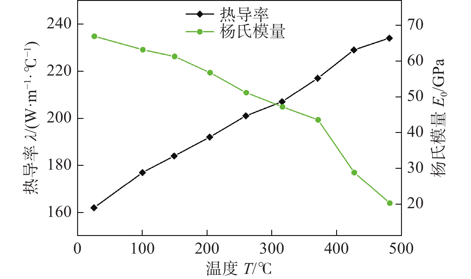
图 3 热导率和杨氏模量与温度的相关性
Figure 3. Correlations of thermal conductivity and Young's modulus with temperature
![]()
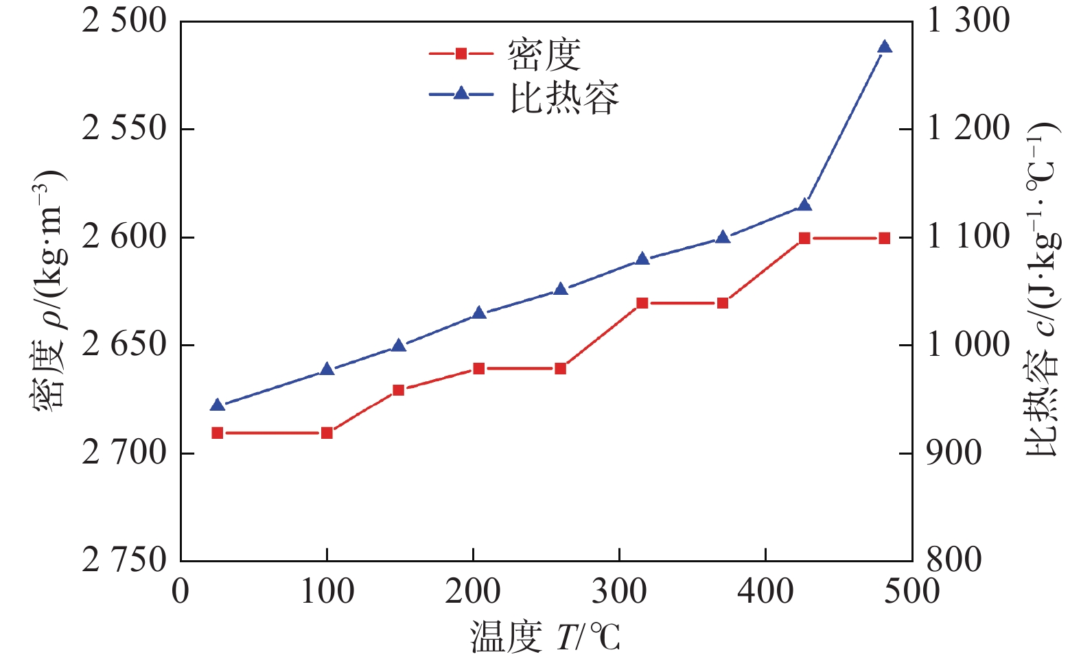
图 4 密度和比热容与温度的相关性
Figure 4. Correlations of density and specific heat capacity with temperature
![]()
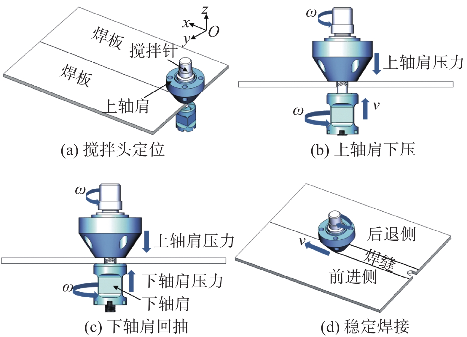
图 6 SSUBT-FSW焊接过程示意图
Figure 6. Schematic illustration of SSUBT-FSW process. (a) positioning stage of the tool; (b) downforce stage of the upper shoulder; (c) pumping back stage of the lower shoulder; (d) stable welding
![]()
图 7 SSUBT-FSW接头表面宏观形貌
Figure 7. Surface macromorphology of the SSUBT-FSWed joint. (a) entry stage;(b) stable welding stage;(c) exit stage
![]()
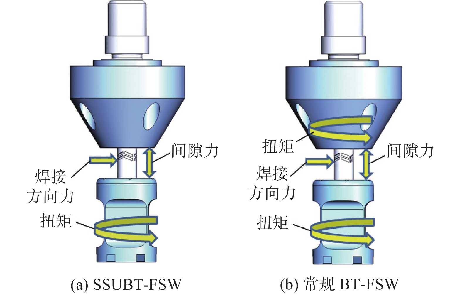
图 8 SSUBT-FSW和常规BT-FSW过程中搅拌头的受力示意图
Figure 8. Force diagram of the stirring tool in SSUBT-FSW and conventional BT-FSW process. (a)SSUBT-FSW;(b) conventional BT-FSW
![]()
图 9 SSUBT-FSW和常规BT-FSW过程中搅拌头的载荷变化
Figure 9. Loading variation of the stirring tool in SSUBT-FSW and conventional BT-FSW process. (a) SSUBT-FSW; (b) conventional BT-FSW
![]()
图 10 SSUBT-FSW接头表面形貌
Figure 10. Surface morphology of the SSUBT-FSWed joint. (a) morphology of the lower surface; (b) morphology of the upper surface; (c) arc orrugation cloud maps of the lower surface; (d) arc orrugation cloud maps of the upper surface; (e) curves of arc orrugation
![]()
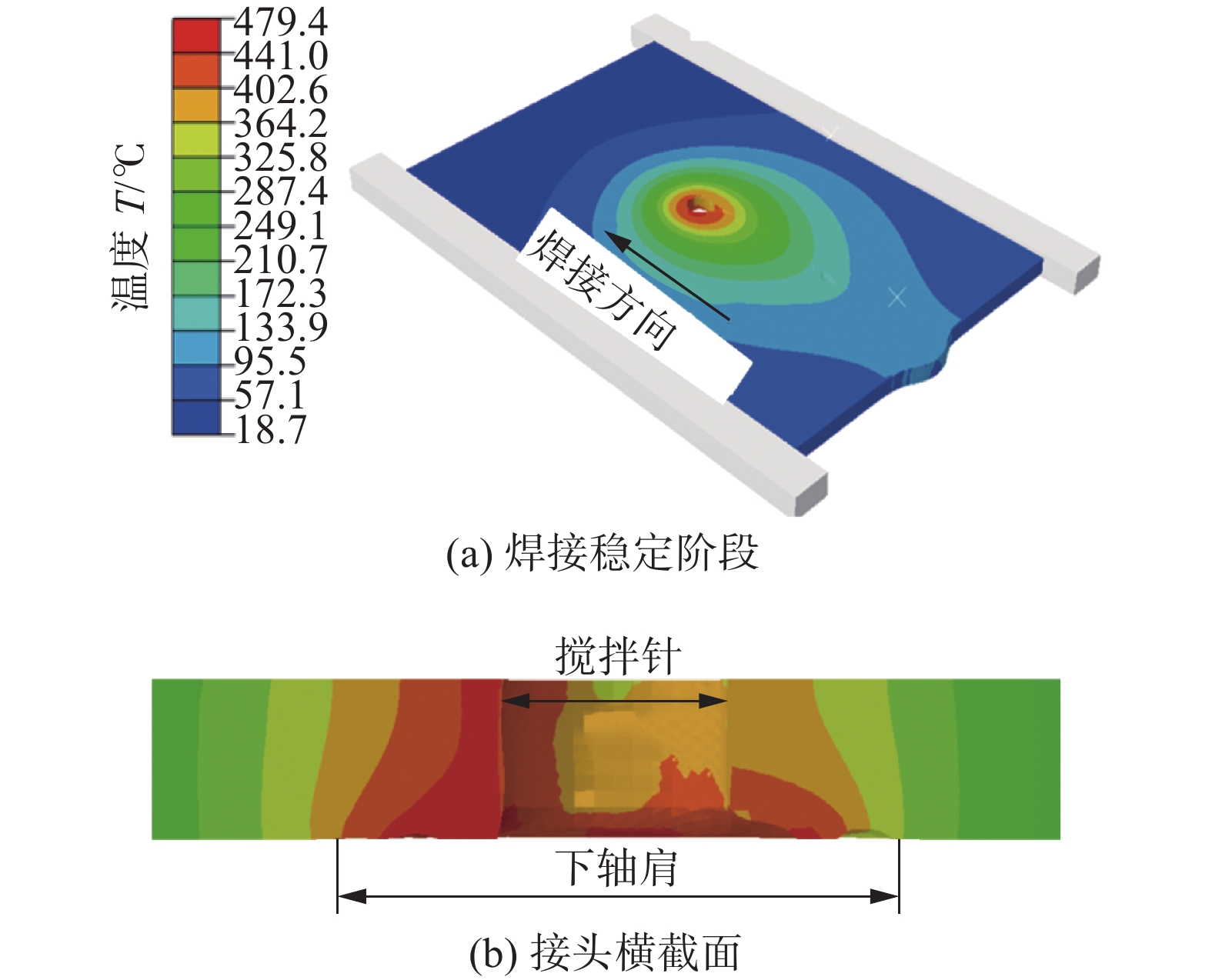
图 11 SSUBT-FSW数值模拟温度场
Figure 11. Simulated temperature contours of SSUBT-FSW. (a) steady state of welding; (b) cross-section of the joint
![]()
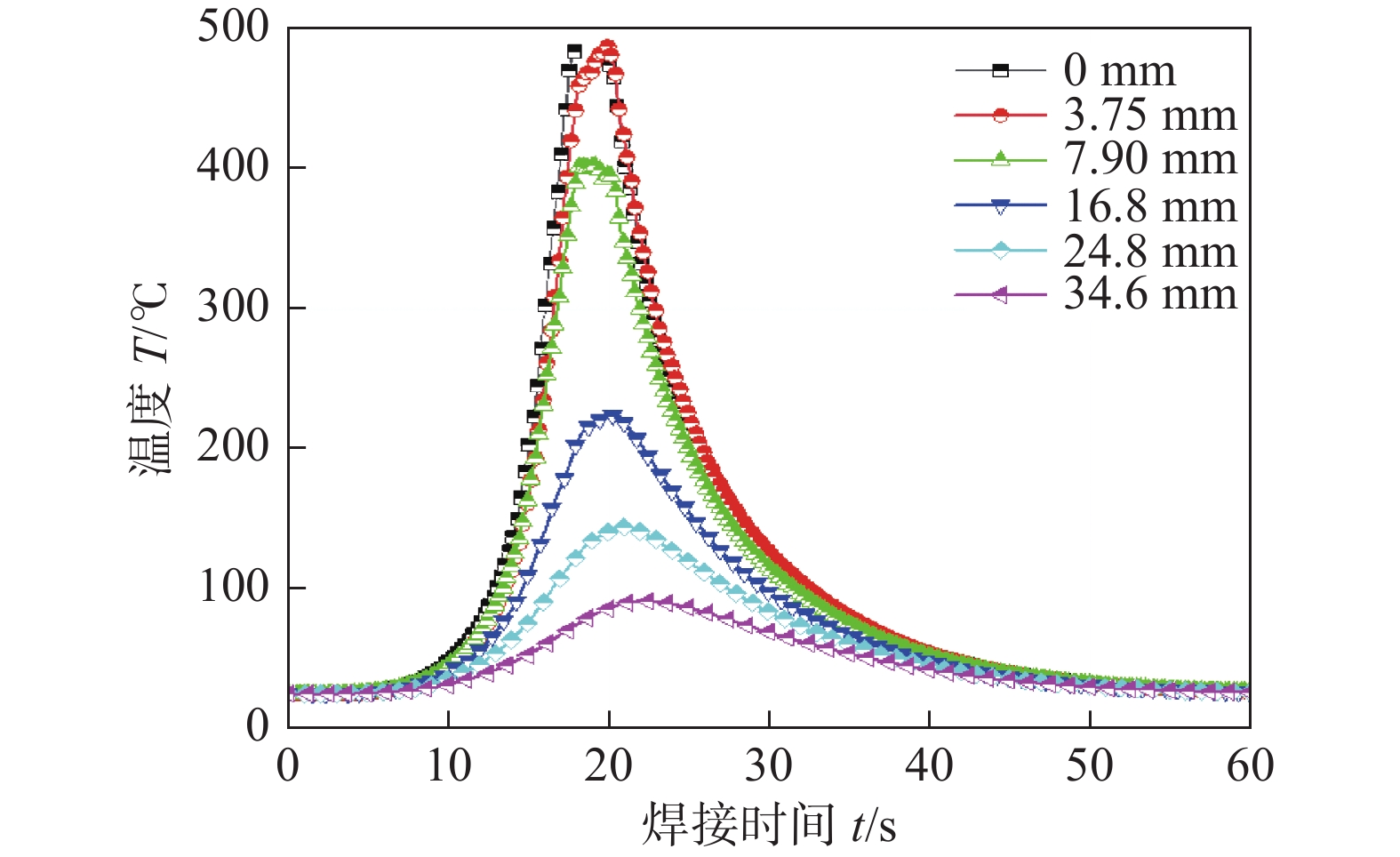
图 12 距离焊缝中心不同位置的温度循环曲线
Figure 12. Thermal cycle curves at different positions from weld center
![]()
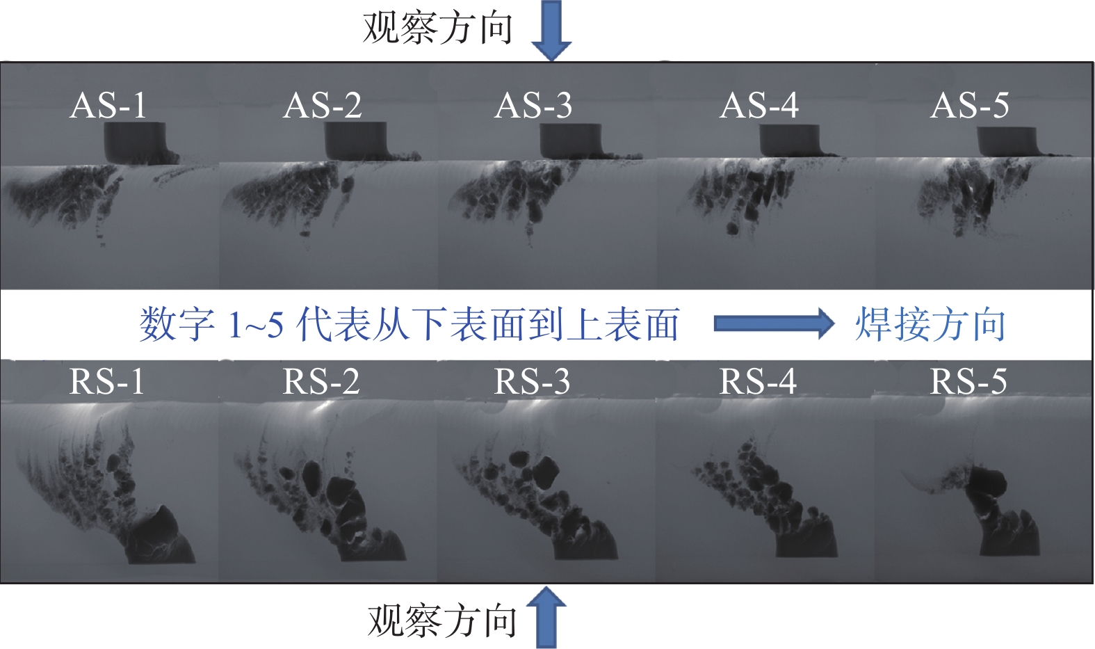
图 14 沿水平方向不同位置的示踪材料分布
Figure 14. Distribution of tracer material at different locations along the horizontal direction
![]()
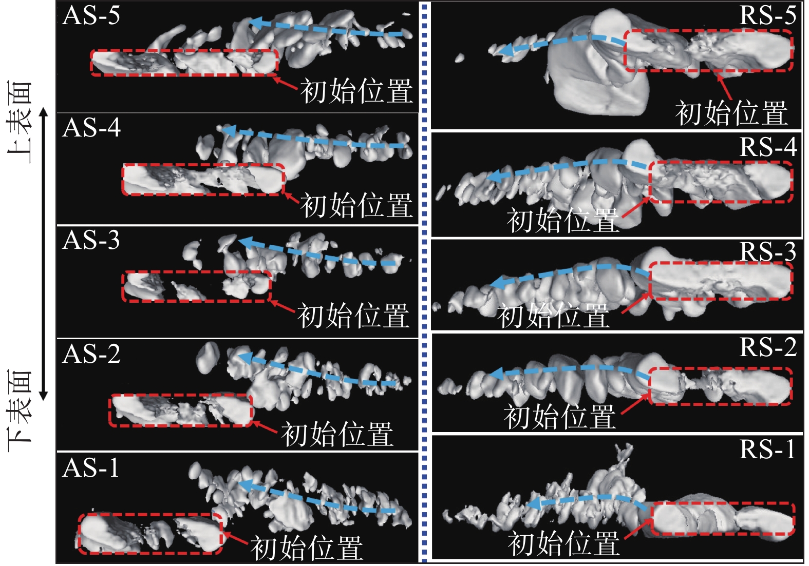
图 15 沿垂直方向不同位置的示踪材料分布
Figure 15. Distribution of tracer material at different locations along the vertical direction
![]()
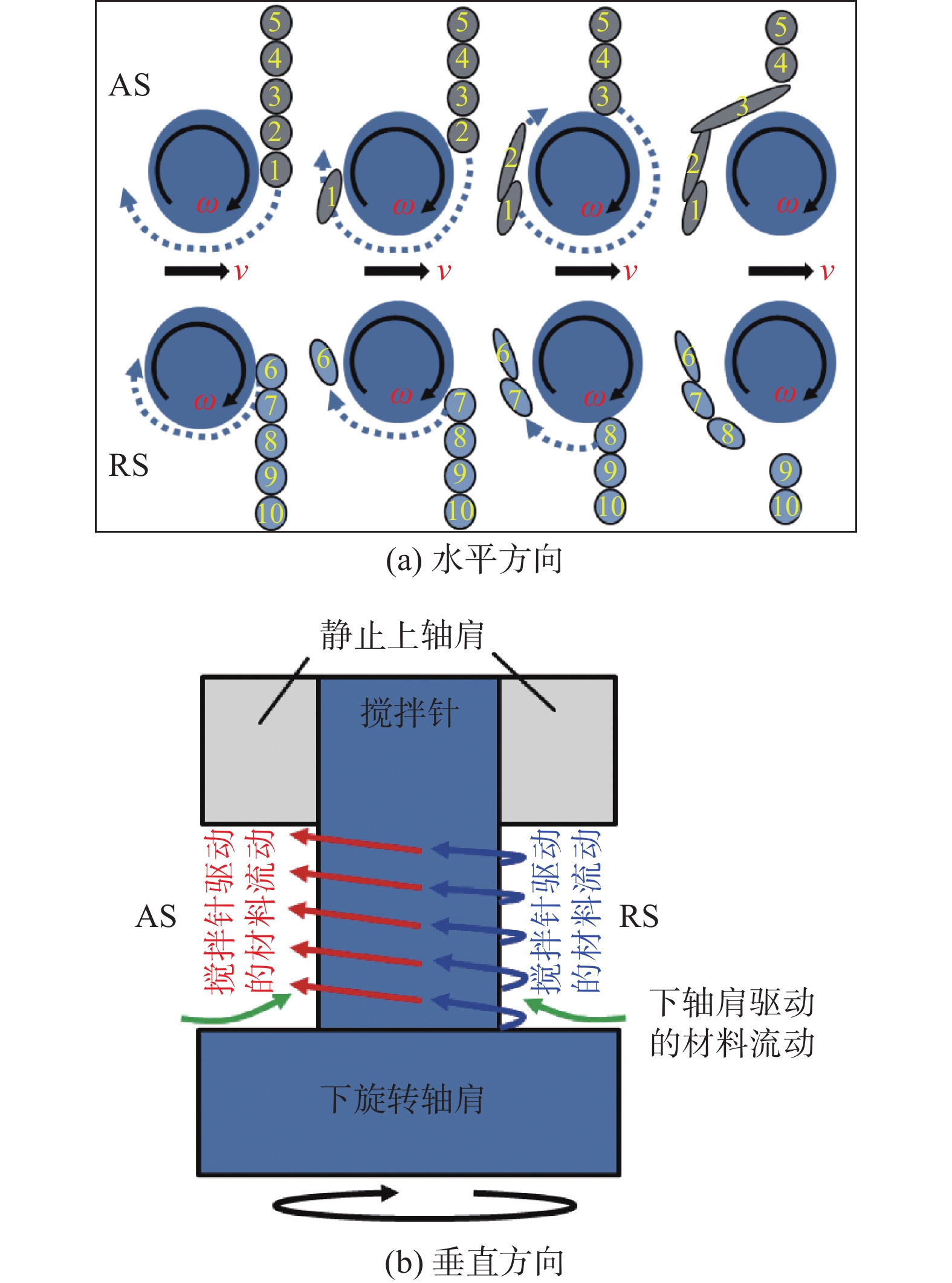
图 16 SSUBT-FSW材料流动模型
Figure 16. Models of material flow in SSUBT-FSW process. (a) horizontal direction; (b) vertical direction
表 1 AA6056-T4铝合金的化学成分(质量分数,%)
Table 1 Chemical compositions of AA6056-T4 aluminum alloy
Si Mg Cu Mn Fe Zn Ti Cr Al 1.18 0.712 0.696 0.657 0.178 0.19 0.009 0.043 余量  下载: 导出CSV
表 2 Johnson-Cook模型参数
Table 2 Johnson-Cook parameters
初始屈服
强度A/MPa硬化模量
B/MPa应变率
系数C应变硬化
系数n软化系数
m熔点
Tmelt/°C324 114 0.002 0.42 1.34 583
下载: 导出CSV
-
[1] 贺地求, 胡雷, 赵志峰, 等. 超声功率对2219-T351 铝合金搅拌摩擦焊接头组织与性能的影响[J]. 焊接学报, 2020, 41(3): 23 − 28. He Diqiu, Hu Lei, Zhao Zhifeng, et al. Effect of ultrasonic power on microstructure and properties of 2219-T351 aluminum alloy friction stir welding joint[J]. Transactions of the China Welding Institution, 2020, 41(3): 23 − 28.
[2] 刘西畅, 李文亚, 高彦军, 等. 铝合金双轴肩搅拌摩擦焊过程材料流动行为[J]. 焊接学报, 2021, 42(3): 48 − 56. doi: 10.12073/j.hjxb.20201228002 Liu Xichang, Li Wenya, Gao Yanjun, et al. Material flow behavior during bobbin-tool friction stir welding of aluminum alloy[J]. Transactions of the China Welding Institution, 2021, 42(3): 48 − 56. doi: 10.12073/j.hjxb.20201228002
[3] Wen Q, Li W Y, Patel V, et al. Investigation on the effects of welding speed on bobbin tool friction stir welding of 2219 aluminum alloy[J]. Metals and Materials International, 2020, 26: 1830 − 1840. doi: 10.1007/s12540-019-00450-9
[4] Dos Santos J F, Hilgert J. Apparatus for friction stir welding: US8893951 B2[P]. 2014.
[5] Scupin P J. Semi-stationary shoulder bobbin tool (S3BT): a new approach in high speed friction stir welding[D]. Hamburg: Technischen Universität Hamburg-Harburg, 2015.
[6] Goebel J, Reimann M, Norman A, et al. Semi-stationary shoulder bobbin tool friction stir welding of AA2198-T851[J]. Journal of Materials Processing Technology, 2017, 245: 37 − 45. doi: 10.1016/j.jmatprotec.2017.02.011
[7] Olea C A W, Roldo L, dos Santos J F, et al. A sub-structural analysis of friction stir welded joints in an AA6056 Al-alloy in T4 and T6 temper conditions[J]. Materials Science and Engineering: A, 2007, 454-455: 52 − 62. doi: 10.1016/j.msea.2006.12.055
[8] Johnson G R, Cook W H. A constitutive model and data for metals subjected to large strains, high strain rates and high temperatures[C]//7th International Symposium on Ballistics. The Hague, The Netherlands, 1983: 541 − 547.
[9] Chauhan P, Jain R, Pal S K, et al. Modeling of defects in friction stir welding using coupled eulerian and lagrangian method[J]. Journal of Manufacturing Processes, 2018, 34: 158 − 166. doi: 10.1016/j.jmapro.2018.05.022
[10] Li W Y, Wang F F. Modeling of continuous drive friction welding of mild steel[J]. Materials Science and Engineering:A, 2011, 528(18): 5921 − 5926. doi: 10.1016/j.msea.2011.04.001
[11] Schmidt H, Hattel J. A local model for the thermomechanical conditions in friction stir welding[J]. Modelling and Simulation in Materials Science and Engineering, 2005, 13(1): 77 − 93. doi: 10.1088/0965-0393/13/1/006
[12] Bastier A, Maitournam M H, Dang V K, et al. Steady state thermomechanical modelling of friction stir welding[J]. Science and Technology of Welding and Joining, 2013, 11(3): 278 − 288.
[13] 邓永芳, 左敦稳, 宋波, 等. 铝合金FSW接头弧纹形成过程及主要影响因素分析[J]. 焊接学报, 2014, 35(7): 43 − 46. Deng Yongfang, Zuo Dunwen, Song Bo, et al. Analysis of formation process and main factors of arc lines in aluminum alloy friction stir welded joint[J]. Transactions of the China Welding Institution, 2014, 35(7): 43 − 46.
[14] 郝云飞, 马建波, 毕煌圣, 等. 铝合金T形接头静止轴肩搅拌摩擦焊接及组织性能分析[J]. 焊接学报, 2019, 40(7): 48 − 54. doi: 10.12073/j.hjxb.2019400180 Hao Yunfei, Ma Jianbo, Bi Huangsheng, et al. Analysis of microstructure and mechanical properties of the aluminum alloy T-joint welded by stationary shoulder friction stir welding[J]. Transactions of the China Welding Institution, 2019, 40(7): 48 − 54. doi: 10.12073/j.hjxb.2019400180
-
期刊类型引用(3)
1. 高成龙,李宪爽,徐祥久. 钛与钢异种材料焊接技术的研究进展. 电站辅机. 2024(01): 23-29 .  百度学术
百度学术
2. 刘自刚,徐睦忠,谭超,傅如斌,代锋先. 钛/钢异种金属熔化焊研究现状与展望. 材料导报. 2024(S2): 358-361 . 百度学术
3. 王俊恒,李锡伟,唐兴全,向强,蒋雪梅. TA2阵列式密集焊缝的TIG自动焊技术. 压力容器. 2022(02): 83-88 . 百度学术
其他类型引用(2)


计量
- 文章访问数: 473
- HTML全文浏览量: 52
- PDF下载量: 43
- 被引次数: 5
