
Preparation of TiC/Fe composite layer on the surface of GCr15 and its binding performance with matrix
-
摘要: 研究以GCr15和TC4为原料,采用热压扩散原位反应在GCr15表面制备TiC/Fe复合层. 利用X射线衍射仪(XRD)、扫描电子显微镜(SEM)、自动划痕仪和显微硬度仪测试表征复合层的物相组成、显微组织、复合层的界面结合性能和显微硬度的变化. 结果表明,在1000 ℃和40 MPa条件下保温2 h,4 h和6 h后,TiC/Fe复合层厚度分别为5 μm,7 μm和10 μm,复合层厚度均匀,与基体界面平整,其表面物相组成仅为TiC和α-Fe相,复合层的显微硬度最高达到2453.7 HV0.05,约为轴承钢基体的5倍. 显微划痕与拉伸试验可知1000 ℃和40 MPa条件下保温4 h所得复合层与基体界面结合的临界载荷为58.5 N,界面结合强度大于221 MPa,表明热压扩散原位制备GCr15表面TiC/Fe复合层与基体之间具有优异的结合性能,对基体保护作用良好.Abstract: In this study, A TiC/Fe composite layer was prepared on the surface of GCr15 using hot pressure diffusion in situ reaction. X-ray diffractometer (XRD), scanning electron microscopy (SEM), automatic scratching instrument and microhardness apparatus were used to characterize the phase composition, microstructure, interface binding properties of the composite layer and changes in microhardness. The results show that the thickness of the TiC/Fe composite layer after insulation for 2 h, 4 h and 6 h at 1 000 ℃, 40 MPa is 5 μm, 7 μm and 10 μm, respectively, the thickness of the composite layer is uniform, the interface with the matrix is flat. The surface phase composition is only TiC and α-Fe phase, and the microhardness of the composite layer is up to 2 453.7 HV0.05, which is about 5 times that of the bearing steel matrix. Micro scratching and tensile tests show that the critical load of the composite layer bonding to the matrix interface at 1 000 ℃, 40 MPa for 4 h is 58.5 N, and the interfacial bonding strength is greater than 221 MPa. The results show that the TiC/Fe composite layer on the surface of GCr15 prepared by hot compression diffusion in situ has excellent binding properties and good matrix protection effect.
-
0. 序言
轴承钢GCr15作为制造轴承的专用结构钢,主要用于制作轴承、滚珠等,在海洋制备、化工机械、石油装备等行业得到广泛应用[1]. 随着机械设备日趋大型化和高效化,单纯的轴承钢GCr15已经难以满足关键轴承可靠性以及承载能力的进一步提升的需求[2].
作为提高金属材料表面力学性能的有效方法之一,在金属基体表面制备陶瓷增强的复合层,可使所得材料不仅具备金属基体的高韧性、高延展性,还具备陶瓷高硬度、耐磨等特性[3]. 表面复合层的制备方法主要有:原位反应技术[4-5]、放热弥散技术[6]、原位熔铸技术[7]、自蔓延高温合成技术[8]和粉末冶金法[9-10]等。Zhang等人[11]利用激光熔覆的方式在40Cr上制备TiC颗粒增强的Fe基复合涂层,其中TiC质量分数为50%时,涂层的耐磨性能为最佳. Khalili等人[12]在AISI 1030表面制备Fe-TiC复合层,其显微硬度是基体的 4 倍. 宋欢[13]以Ti-Fe + Si 为原材料原位生成TiC增强镍基喷焊层,与直接单掺Ti-Fe粉相比,耐磨性约为后者的79%. 董运涛等人[14]通过热轧复合的方法在800 ~ 850 ℃下采用氩气保护制备的钛钢复合板,其剪切强度大于170 MPa. 采用热压扩散原位反应在GCr15表面制备一层TiC/Fe复合层,并对制备所得复合层的组织结构、物相组成、显微硬度以及TiC/Fe复合层与基体的结合强度进行了研究.
1. 试验方法
以GCr15和TC4为原料,利用电火花线切割将轴承钢和钛合金分别加工成ϕ20 mm × 22 mm (GCr15)和ϕ20 mm × 1 mm (TC4)圆柱(片),GCr15和TC4的化学成分如表1所示. 使用120 ~ 2 000号金相砂纸将切割的轴承钢表面和钛合金圆片逐级打磨直至表面光滑. 将轴承钢与钛合金板按如图1所示叠放,并用石墨纸包覆置于模具中,在快速热压烧结炉(FHP-828)内于1000 ℃,40 MPa压力下选择不同时间加热保温.
表 1 GCr15和TC4的化学成分(质量分数,%)Table 1. Chemical constituents of GCr15 and TC4材料 Fe C Si Mn Cr Mo Ti Al V N GCr15 余量 0.95~1.05 0.15~0.35 0.25~0.45 1.40~1.65 ≤0.10 — — — — TC4 0.30 0.08 — — — — 余量 5.50~6.75 3.50~4.50 0.05 利用XRD-7000型衍射仪(XRD)分析复合层的物相组成,工作电压为40 kV、工作电流为40 mA、扫描角度在20°~90°之间、扫描速度8 °/min;采用Merlin Compact型场发射SEM观察TiC/Fe复合层的显微组织及微观形貌. 利用 DHV-1000Z 显微硬度计测试不同区域硬度值,施加载荷为50 g,保压时间10 s. 使用WS-2005型自动划痕仪对复合层与基体的结合性能进行表征,以100 N/min速度实现0 ~ 100 N连续加载,划痕长度5 mm. 为进一步对所得增强层与基体结合强度进行量化,制备三明治结构试样,其结构示意如图2所示,从中切取长度为36 mm标准板状拉伸试样,以0.45 mm/min速率对其进行恒应变单轴加载拉伸.
![]() 图 2 拉伸试样的制备及其试验样品尺寸Figure 2. Schematic diagram of tensile test specimens. (a) sandwich sample; (b) Tensile specimen prepared
图 2 拉伸试样的制备及其试验样品尺寸Figure 2. Schematic diagram of tensile test specimens. (a) sandwich sample; (b) Tensile specimen prepared2. 结果与讨论
2.1 物相及组织形貌
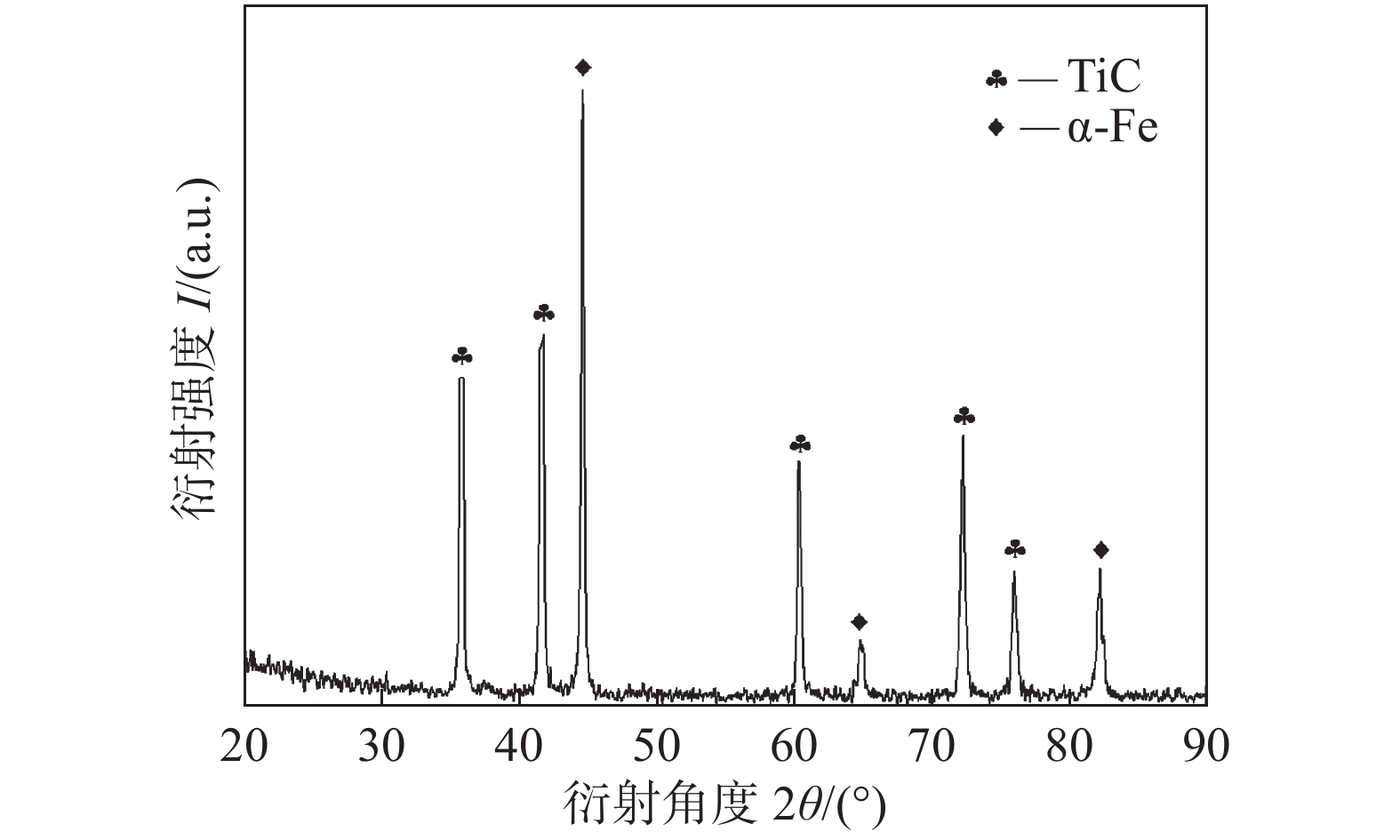
图3为1000 ℃,40 MPa,4 h时TiC/Fe复合层表面XRD图谱,分析可知复合层中仅存在TiC和α-Fe相. 由此可知,热压加工过程,轴承钢中碳原子扩散充分并且与钛原子发生原位反应生成碳化钛,并未产生Ti2C等其他杂相.
![]() 图 3 1000 ℃,40 MPa,4 h轴承钢表面TiC/Fe复合层XRD图谱Figure 3. XRD analysis results of TiC/Fe composite layer on bearing steel surface at 1000 ℃,40 MPa,4 h
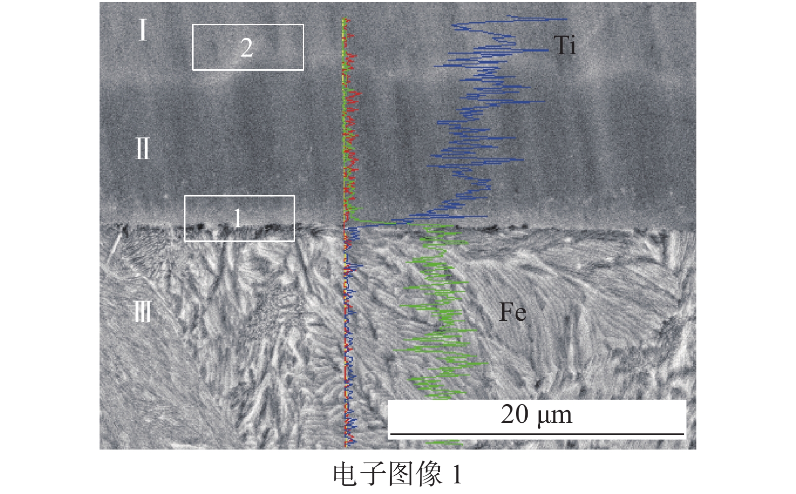
图 3 1000 ℃,40 MPa,4 h轴承钢表面TiC/Fe复合层XRD图谱Figure 3. XRD analysis results of TiC/Fe composite layer on bearing steel surface at 1000 ℃,40 MPa,4 h图4为GCr15表面TiC/Fe复合层的SEM照片,在1000 ℃,40 MPa条件下所得试样分为三层,分别是未反应完的TC4层、TiC/Fe复合层和GCr15基体. 1000 ℃,40 MPa下保温2 h、4 h和6 h制备的轴承钢表面TiC/Fe复合层厚度分别为5 μm、7 μm和10 μm,随保温时间的延长TiC/Fe复合层的层厚明显增加,所得复合层厚度均匀,与基体界面平整.
![]() 图 4 在1000 ℃,40 MPa不同保温时间下样品的扫描照片Figure 4. Scanning photos of samples at different holding times of 1000 ℃,40 MPa. (a) 2 h/5 μm; (b) 4 h/7 μm; (c) 6 h/10 μm
图 4 在1000 ℃,40 MPa不同保温时间下样品的扫描照片Figure 4. Scanning photos of samples at different holding times of 1000 ℃,40 MPa. (a) 2 h/5 μm; (b) 4 h/7 μm; (c) 6 h/10 μm图5是沿TC4板法向的线扫描能谱分析的结果,线扫描的区域从上至下横穿Ⅰ、Ⅱ、Ⅲ 3个区域分别是未反应完的TC4、TiC/Fe复合层和轴承钢基体. 轴承钢中的碳原子在高温和压力的作用下不断的扩散入钛合金板中,并与钛合金板中的钛原子反应生成碳化钛. 同时因为轴承钢基体中碳原子不断向钛合金区域扩散,致使Ⅲ区域碳原子浓度有所下降. 在1000 ℃时轴承钢和钛合金中的其他合金元素原子仅发生少量扩散,因此在Ⅰ、Ⅱ区域中仅存在少量铁元素,Ⅲ区域内存在极少量钛元素. 热压扩散原位制备GCr15表面TiC/Fe复合层时,包含轴承钢与碳化钛结合的界面1以及未反应的钛合金与碳化钛结合的界面2. 图中界面1与界面2有明显的差别,其中界面1可以清晰可见,平直整齐,而界面2呈明显波浪式. 轴承钢中的铁原子和钛合金中的钛原子均未大量扩散进入对方区域,故在轴承钢与钛合金板接触面为平直界面. 界面2是由于碳元素从轴承钢基体中大量扩散入钛合金中发生反应,碳原子扩散通量不同形成的.
2.2 显微硬度
表2为1000 ℃,40 MPa,4 h所得TiC/Fe复合层的显微维氏硬度,最高可达2 453.7 HV,该值略低于纯碳化钛陶瓷的硬度(2 800 HV)[15]. 主要原因是在1000 ℃,40 MPa热压扩散原位反应时,轴承钢基体中Fe处于其泰曼温度以上,Fe元素的扩散使得此处为碳化钛陶瓷与铁的复合,并非纯的碳化钛陶瓷层. 图6为未反应钛合金板、TiC/Fe复合层和轴承钢基体的硬度的平均值. 从图中可明显看出,轴承钢表面的TiC/Fe 复合层的显微硬度是基体的5倍,约为未反应钛合金板的4 倍.
表 2 TiC/Fe复合层的硬度(HV0.05)Table 2. Hardness of TiC/Fe composite layer1 2 3 4 5 平均值 1999.8 1824.7 1903.9 1843.0 2453.7 2005.0 ![]() 图 6 未反应钛合金板、复合层和基体的显微硬度变化趋势Figure 6. Microhardness variation trend of unreacted titanium alloy plate, composite layer and substrate
图 6 未反应钛合金板、复合层和基体的显微硬度变化趋势Figure 6. Microhardness variation trend of unreacted titanium alloy plate, composite layer and substrate2.3 划痕试验结果分析
图7a和7b是GCr15表面TiC/Fe复合层的显微刻划的声发射曲线. 保温2 h所得复合层发生破坏的临界载荷40 N,4 h所得复合层发生破坏的临界载荷为58.5 N,随保温时间的延长,复合层厚增加,其与基体结合强度逐渐增大. 从图7c可以发现在刻划的过程中试样表面TiC/Fe复合层受到压头加载作用发生变形,最初为弹性变形,随着法向加载的增大逐渐出现塑性变形,直到陶瓷层底部萌生裂纹,裂纹扩展连接,致使隆起部位发生破裂. 图7c为显微划痕的整体形貌照片,其特征部位的深度与宽度如表3所示,随着原位反应时间的延长,保温4 h 所得增强层刻划后划痕的深度明显低于保温 2 h所得增强层划痕的深度.
![]() 图 7 划痕试验结果Figure 7. Results of scratch experiment. (a) 2 h acoustic emission curve; (b) 4 h acoustic emission curve; (c) 2 & 4 h overall morphology of scratch表 3 划痕的深度与宽度Table 3. Depth and width of scratches
图 7 划痕试验结果Figure 7. Results of scratch experiment. (a) 2 h acoustic emission curve; (b) 4 h acoustic emission curve; (c) 2 & 4 h overall morphology of scratch表 3 划痕的深度与宽度Table 3. Depth and width of scratches序号 宽度D/μm 深度H/μm 1 115.25 5.86 2 161.25 7.77 3 173.25 9.66 4 198.75 14.85 1′ 111.25 0.97 2′ 130.50 5.34 3′ 197.75 7.62 图8是1000 ℃,40 MPa,2 h划痕中部和末端微观形貌图. 在压头行进过程中,垂直加载不断增大,当载荷大于40 N时,划痕边缘部位有断续的呈三角形的陶瓷层剥落,即产生与划痕方向呈45 °的裂纹扩展,如图8a中A处所示. 当载荷为100 N时,TiC/Fe复合层发生剧烈的塑性变形并出现破裂和剥落,划痕底部存在贯穿划痕宽度方向的裂纹[16],如图8b中B处所示. 此时划痕深度已超过14.85 μm,而1000 ℃,40 MPa,2 h试样的复合层厚度约为5 μm,划痕深度已经完全贯穿整个TiC/Fe复合层,但复合层未出现大面积的胀裂和破坏,表明复合层与基体结合强度较高,对基体保护作用良好.
![]()
2.4 拉伸试验结果分析
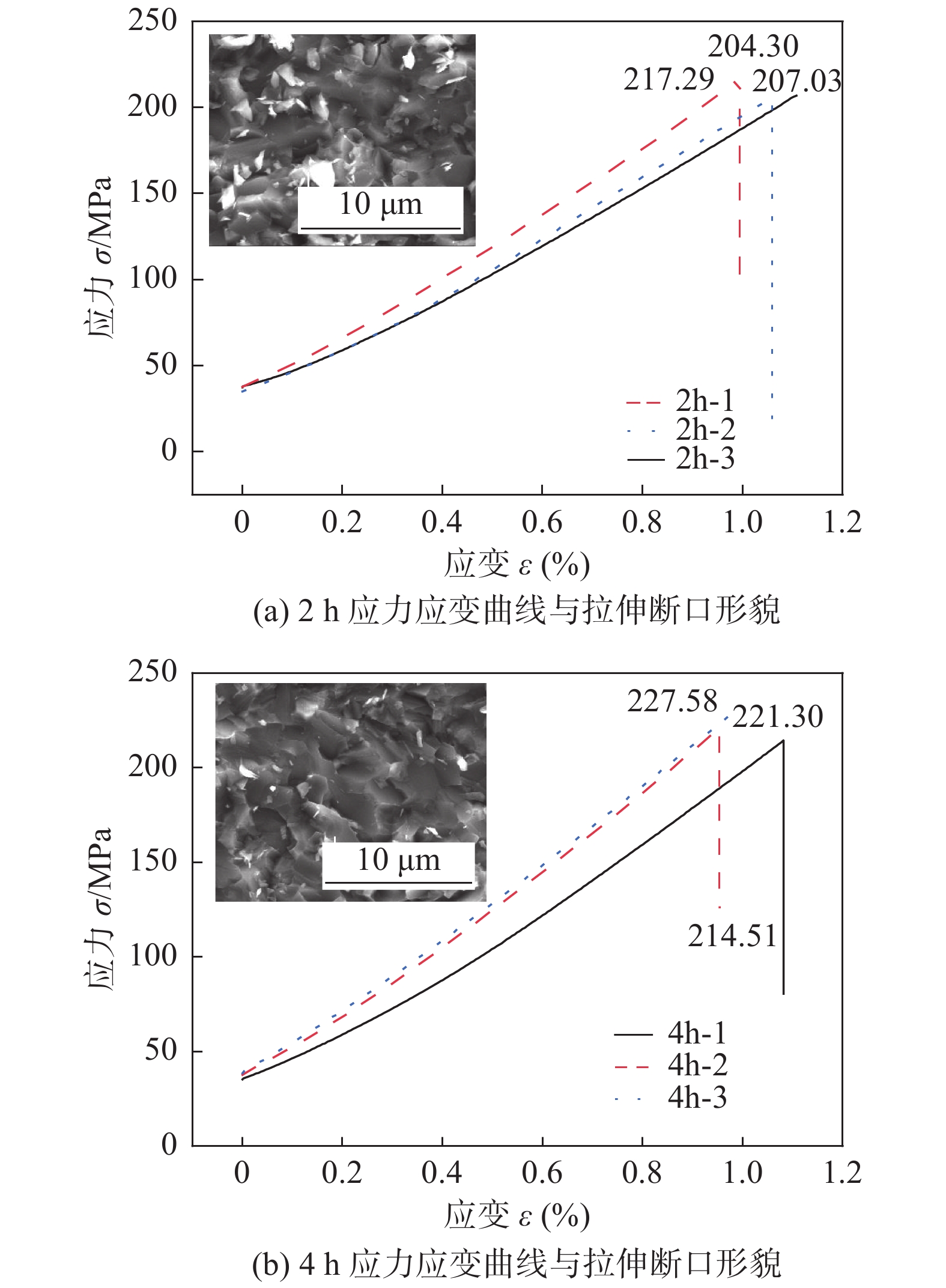
图9为1000 ℃,40 MPa,2/4 h三明治结构试样拉伸的应力应变曲线和断口形貌,从拉伸曲线可知为脆性断裂. 图9a和9b中的插图中可以看到碳化钛颗粒的形状与分布状况,判断可知试样的断裂均发生在TiC/Fe复合层的层间.
![]() 图 9 1000 ℃,40 MPa,2/4 h应力应变曲线与拉伸断口形貌Figure 9. Stress-strain curves and tensile fracture morphology at 1000 ℃,40 MPa,2/4 h. (a) 2 h stress-strain curve and tensile fracture morphology; (b) 4 h stress-strain curve and tensile fracture morphology
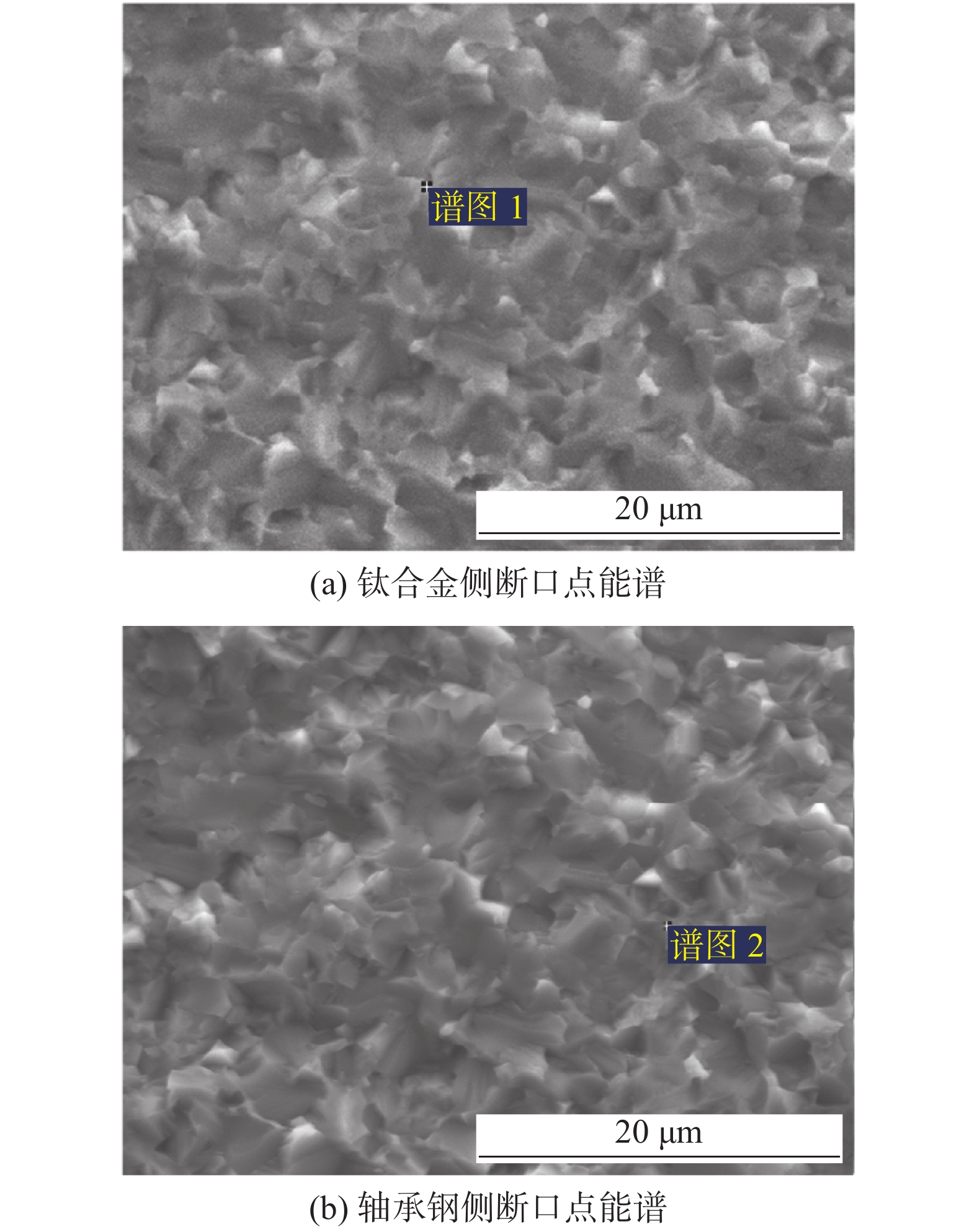
图 9 1000 ℃,40 MPa,2/4 h应力应变曲线与拉伸断口形貌Figure 9. Stress-strain curves and tensile fracture morphology at 1000 ℃,40 MPa,2/4 h. (a) 2 h stress-strain curve and tensile fracture morphology; (b) 4 h stress-strain curve and tensile fracture morphology为了进一步确定断裂发生的位置,对拉伸试样断口的两侧进行能谱分析,点能谱的位置如图10所示,其相应的能谱分析结果在表4列出,谱图1中存在大量Ti元素和C元素以及少量的Fe元素,谱图2的元素与谱图1的元素分布相近,根据质量百分比计算可知Ti和C的原子百分比近似1∶1,即1点与2点均在TiC/Fe复合层的层间. 由三明治结构试样拉伸试验曲线可知, 1000 ℃-40 MPa保温2 h试样的界面结合强度约为210 MPa,保温4 h试样的界面结合强度约为221 MPa.
![]() 图 10 拉伸断口两侧点能谱分析位置Figure 10. Position of energy spectrum analysis of points on both sides of tensile fracture. (a) fracture energy spectrum of titanium alloy side; (b) fracture energy spectrum of bearing steel side表 4 拉伸试样断口点能谱分析结果(质量分数,%)Table 4. Energy spectrum analysis results of fracture points of tensile specimens
图 10 拉伸断口两侧点能谱分析位置Figure 10. Position of energy spectrum analysis of points on both sides of tensile fracture. (a) fracture energy spectrum of titanium alloy side; (b) fracture energy spectrum of bearing steel side表 4 拉伸试样断口点能谱分析结果(质量分数,%)Table 4. Energy spectrum analysis results of fracture points of tensile specimens谱图 C Ti Fe 谱图1 20.88 78.68 0.44 谱图2 19.30 76.42 4.29 3. 结论
(1)以轴承钢和TC4为原材料,通过1000 ℃-40 MPa原位热压扩散制备所得TiC/Fe复合层厚度均匀、界面干净平整. 增强层的主要物相组成为TiC与极少量α-Fe相,TiC/Fe 复合层显微硬度最高达到 2 453.7 HV.
(2)随增强层厚度增加,TiC/Fe复合层与轴承钢基体的结合强度增强,显微刻划中的主要失效破坏为小范围的破裂和剥落. 拉伸试验的断裂均发生在制备所得复合层内,复合层与基体呈现良好的冶金结合,两者的结合强度大于复合层强度,其中保温4 h试样界面结合强度约为221 MPa.
(3)热压扩散原位制备GCr15表面TiC/Fe复合层与基体之间具有优异宏观结合性能,对基体保护作用良好.
-
![]()
图 2 拉伸试样的制备及其试验样品尺寸
Figure 2. Schematic diagram of tensile test specimens. (a) sandwich sample; (b) Tensile specimen prepared
![]()
图 3 1000 ℃,40 MPa,4 h轴承钢表面TiC/Fe复合层XRD图谱
Figure 3. XRD analysis results of TiC/Fe composite layer on bearing steel surface at 1000 ℃,40 MPa,4 h
![]()
图 4 在1000 ℃,40 MPa不同保温时间下样品的扫描照片
Figure 4. Scanning photos of samples at different holding times of 1000 ℃,40 MPa. (a) 2 h/5 μm; (b) 4 h/7 μm; (c) 6 h/10 μm
![]()
图 6 未反应钛合金板、复合层和基体的显微硬度变化趋势
Figure 6. Microhardness variation trend of unreacted titanium alloy plate, composite layer and substrate
![]()
图 7 划痕试验结果
Figure 7. Results of scratch experiment. (a) 2 h acoustic emission curve; (b) 4 h acoustic emission curve; (c) 2 & 4 h overall morphology of scratch
![]()
![]()
图 9 1000 ℃,40 MPa,2/4 h应力应变曲线与拉伸断口形貌
Figure 9. Stress-strain curves and tensile fracture morphology at 1000 ℃,40 MPa,2/4 h. (a) 2 h stress-strain curve and tensile fracture morphology; (b) 4 h stress-strain curve and tensile fracture morphology
![]()
图 10 拉伸断口两侧点能谱分析位置
Figure 10. Position of energy spectrum analysis of points on both sides of tensile fracture. (a) fracture energy spectrum of titanium alloy side; (b) fracture energy spectrum of bearing steel side
表 1 GCr15和TC4的化学成分(质量分数,%)
Table 1 Chemical constituents of GCr15 and TC4
材料 Fe C Si Mn Cr Mo Ti Al V N GCr15 余量 0.95~1.05 0.15~0.35 0.25~0.45 1.40~1.65 ≤0.10 — — — — TC4 0.30 0.08 — — — — 余量 5.50~6.75 3.50~4.50 0.05  下载: 导出CSV
表 2 TiC/Fe复合层的硬度(HV0.05)
Table 2 Hardness of TiC/Fe composite layer
1 2 3 4 5 平均值 1999.8 1824.7 1903.9 1843.0 2453.7 2005.0
下载: 导出CSV
表 3 划痕的深度与宽度
Table 3 Depth and width of scratches
序号 宽度D/μm 深度H/μm 1 115.25 5.86 2 161.25 7.77 3 173.25 9.66 4 198.75 14.85 1′ 111.25 0.97 2′ 130.50 5.34 3′ 197.75 7.62
下载: 导出CSV
表 4 拉伸试样断口点能谱分析结果(质量分数,%)
Table 4 Energy spectrum analysis results of fracture points of tensile specimens
谱图 C Ti Fe 谱图1 20.88 78.68 0.44 谱图2 19.30 76.42 4.29
下载: 导出CSV
-
[1] 俞峰, 陈兴品, 徐海峰, 等. 滚动轴承钢冶金质量与疲劳性能现状及高端轴承钢发展方向[J]. 金属学报, 2020, 56(4): 513 − 522. doi: 10.11900/0412.1961.2019.00361 Yu Feng, Chen Xingpin, Xu Haifeng, et al. Current status of metallurgical quality and fatigue performance of rolling bearing steel and development direction of high-end bearing steel[J]. Acta Metall Sin, 2020, 56(4): 513 − 522. doi: 10.11900/0412.1961.2019.00361
[2] 张朝磊, 朱禹承, 蒋波. 高碳铬轴承钢组织双超细化的研究现状与发展趋势[J]. 材料导报, 2023(6): 1 − 12. Zhang Chaolei, Zhu Yucheng, Jiang Bo. Research status and development trend of microstructure double ultra refinement of high carbon chromium bearing steel[J]. Materials Reports, 2023(6): 1 − 12.
[3] 尹洪峰, 任耘, 范强, 等. 反应热压烧结法制备SiC/Ti3SiC2复合材料及其性能[J]. 复合材料学报, 2011, 28(3): 69 − 73. Yin Hongfeng, Reng Yun, Fan Qiang, et al. Fabrication and properties of SiC/Ti3SiC2 composites by reactive hot pressing sintering[J]. Acta Materials Compositae Sinica, 2011, 28(3): 69 − 73.
[4] 刘树英, 张冬冬, 刘亚洲, 等. 钛合金/Cu/不锈钢扩散焊界面化合物生长行为解析[J]. 焊接学报, 2019, 40(9): 133 − 138,167. Chen Shuying, Zhang Dongdong, Liu Yazhou, et al. Analysis of growth behavior of intermetallic compound in diffusion bonding of Ti alloy/Cu/stainless steel[J]. Transactions of the China Welding Institution, 2019, 40(9): 133 − 138,167.
[5] 陈路路, 翟洪祥, 黄振莺, 等. TiCx含量对热压制备TiCx-Fe基复合材料力学性能的影响[J]. 稀有金属材料与工程, 2018, 47(S1): 407 − 411. Chen Lulu, Zhai Hongxiang, Huang Zhenying, et al. Effect of TiCx content on mechanical properties of TiCx-Fe matrix composites prepared by hot pressing[J]. Rare Metal Materials and Engineering, 2018, 47(S1): 407 − 411.
[6] 庄伟彬, 田宗伟, 刘广柱, 等. 原位自生TiCp/6061复合材料的组织、硬度及耐磨性能[J]. 材料导报, 2019, 33(22): 3762 − 3767. doi: 10.11896/cldb.18100185 Zhuang Weibin, Tian Zongwei, Liu Guangzhu, et al. Microstructure, hardness and wear resistance properties of in-situ TiCp/6061 composites[J]. Materials Reports, 2019, 33(22): 3762 − 3767. doi: 10.11896/cldb.18100185
[7] 孙淼, 许存官, 何建平, 等. 熔铸-原位合成TiC/7075复合材料的拉伸和磨损性能[J]. 稀有金属材料与工程, 2009, 38(2): 308 − 312. doi: 10.3321/j.issn:1002-185X.2009.02.027 Sun Miao, Xu Cunguan, He Jianping, et al. Tensile and wear properties of TiC/7075 composite prepared by melt in-situ synthesis[J]. Rare Metal Materials and Engineering, 2009, 38(2): 308 − 312. doi: 10.3321/j.issn:1002-185X.2009.02.027
[8] Lagos M A, Agote I, Atxtaga G, et al. Fabrication and characterisation of titanium matrix composites obtained using a combination of self propagating high temperature synthesis and spark plasma sintering[J]. Materials Science & Engineering A, 2016, 65(5): 44 − 49.
[9] Anton P, Marie J, Gert B, et al. Manufacturing Fe-TiC metal matrix composite by electron beam powder bed fusion from pre-alloyed gas atomized powder[J]. Materials Science & Engineering A, 2021, 813: 141130.
[10] Zhong L S, Wu T D, Zhang X, et al. In situ preparation of titanium carbide ceramic layer on grey cast iron[J]. Materials Science, 2015, 21(4): 586 − 589.
[11] Zhang Z H, Wang X, Zhang Q Q, et al. Fabrication of Fe-based composite coatings reinforced by TiC particles and its microstructure and wear resistance of 40Cr gear steel by low energy pulsed laser cladding[J]. Optics & Laser Technology, 2019, 119: 10562.
[12] Khalili A, Goodarzi M, Mojtahedi M, et al. Solidification microstructure of in-situ laser-synthesized Fe-TiC hard coating[J]. Surface & Coatings Technology, 2016, 307: 747 − 752.
[13] 宋欢. 原位生成TiC增强镍基喷焊层耐磨耐蚀性能研究[D]. 成都: 西华大学, 2020. Song Huan. The research on wear and corrosion resistance of Ni-based coatings by in-situ TiC reinforced[D]. Chengdu: Xihua University, 2020.
[14] 董运涛, 张家毓, 李选明. 钛/钢双金属的可控气氛热复合工艺初探[J]. 稀有金属材料与工程, 2012, 41(S2): 141 − 144. Dong Yuntao, Zhang Jiayu, Li Xuanming. Preliminary study of controlled atmosphere roll bonding process for the titanium-steel bimetal system[J]. Rare Metal Materials and Engineering, 2012, 41(S2): 141 − 144.
[15] 惠鹏飞. 间隙原子渗碳法制备金属(Ta、Mo、Ti6Al4V)表面碳化层的组织和性能研究[D]. 西安: 西安理工大学, 2019. Hui Pengfei. Microstructure and properties of interstitial atom carburizing layer on metal (Ta, Mo, Ti6Al4V) surfaces[D]. Xi’an: Xi’an University of Technology, 2019.
[16] 冯爱新, 叶勇, 殷苏民, 等. 涂层界面失效破坏临界位置的理论分析与实验研究[J]. 中国激光, 2008(11): 1746 − 1751. doi: 10.3321/j.issn:0258-7025.2008.11.015 Feng Aixin, Ye Yong, Yin Sumin, et al. Theoretical analysis and experimental research on the broken critica-position of coating interface[J]. Chinese Journal Lasers, 2008(11): 1746 − 1751. doi: 10.3321/j.issn:0258-7025.2008.11.015


计量
- 文章访问数: 350
- HTML全文浏览量: 51
- PDF下载量: 51
