
Impact performance optimization of supermartensitic stainless steel welding wire deposited metal by MAG welding
-
摘要: 白鹤滩百万千瓦水电机组全部采用国产HS13/5L焊丝进行焊接,成功实现了中国高端装备制造的重大突破. HS13/5L焊丝为水轮机转轮同材质焊接材料,属于13Cr型超级马氏体不锈钢,然而其MAG焊熔敷金属的韧性低于母材,针对此问题,将现有的MAG平焊焊接工艺调整为立向上焊焊接工艺,以提高熔敷金属的冲击韧性.对比分析了平焊、立向上焊熔敷金属的微观组织和冲击性能. 结果表明,立向上焊位置回火热处理态熔敷金属的室温冲击吸收能量达到120 J以上,比平焊位置提高了约40%. 两种焊接位置下的熔敷金属微观组织的相组成无明显差异,焊态组织为淬火马氏体 + 残余奥氏体 + δ-Fe,回火热处理态组织为回火板条马氏体 + 逆变奥氏体 + δ-Fe.立向上焊熔敷金属中的氧化夹杂物密度比平焊位置降低了约22%.平焊和立向上焊熔敷金属冲击断口整体呈现出韧性断裂的特征,立向上焊位置熔敷金属的韧性优于平焊位置.
-
关键词:
- 超级马氏体不锈钢 /
- 熔化极活性气体保护焊 /
- 微观组织 /
- 冲击 /
- 断口形貌
Abstract: Baihetan 1 000 MW hydro unit is all welded with domestic HS13/5L welding wire, which has successfully achieved a major breakthrough in China's high-end equipment manufacturing. HS13/5L welding wire is the welding material identical with the hydraulic turbine runner, belonging to 13Cr supermartensitic stainless steel. However, the toughness of the deposited metal in metal active gas arc (MAG) welding is lower than that of the base metal. In view of this problem, the welding process is adjusted from flat to vertical-up welding position, to improve the impact toughness of MAG welding deposited metal. And the microstructure and impact properties of the deposited metal are compared and analyzed. The results show that the room temperature impact absorption energy of the as-tempered deposited metal in the vertical-up welding position reaches more than 120 J, which is about 40% higher than the flat welding position. There is no obvious difference in the phase composition of the deposited metal microstructure between the two welding positions, the as-welded microstructure is composed of quenched martensite, retained austenite and delta ferrite and the as-tempered microstructure is tempered lath martensite, reversed austenite and delta ferrite. The density of oxide inclusions in the vertical-up welding deposited metal is about 22% lower than the flat welding position. The impact fracture of the deposited metal shows the characteristics of ductile fracture for both welding composition as a whole, and the toughness of the deposited metal in the vertical-up welding position is better than that in the flat welding position. -
0. 序言
超级马氏体不锈钢具有较高的强度、韧性以及良好的耐腐蚀性、抗空蚀性和焊接性等特点,近年来在大型水轮机制造业中得到广泛应用[1]. 超级马氏体不锈钢通常采用淬火 + 回火的热处理工艺. 超级马氏体不锈钢的淬火组织为淬火马氏体和少量残余奥氏体,回火组织为回火马氏体和弥散分布于马氏体基体中的逆变奥氏体[2]. 超级马氏体不锈钢焊接结构的焊缝形成的淬火马氏体呈现出高强低韧的特点,焊后回火热处理能够提高材料的韧性,降低焊缝和热影响区的显微硬度[3-4].回火过程中形成的逆变奥氏体组织,是超级马氏体不锈钢韧性提高的主要原因.
水轮机转轮是水电站的核心部件,目前大型水轮机转轮的材料大多采用超级马氏体不锈钢,转轮的上冠、下环和叶片之间需要进行大量的焊接.国产HS13/5L焊丝相当于AWS A5.9 ER410NiMo实心焊丝,已成功替代进口,广泛用于三峡、白鹤滩等水电站的大型水轮机转轮的焊接.厚截面大型水轮机转轮的焊接通常采用传统的多道次电弧焊工艺[5],其中氩弧焊的焊接效率低下[6],不适合在转轮大厚度焊缝焊接中应用,目前转轮焊接大多采用熔化极活性气体保护焊(metal active gas arc welding, MAG焊). 然而MAG焊熔敷金属的冲击韧性不足母材的2/3,焊接接头仍为水轮机转轮性能较薄弱的部位[7],随着中国水电事业的发展,更为严苛的工况条件会对水轮机转轮的冲击性能提出更高的要求,所以有必要进一步提高熔敷金属的冲击韧性.
裴冲等人[8]和牟淑坤等人[9]分别研究了横焊与立焊、平焊与立焊位置下焊缝的组织和韧性,结果表明,不同焊接位置下焊缝的微观组织、晶粒特征、焊接缺陷等方面可能存在差异,立焊位置下的焊缝具有更高的韧性. 目前对于超级马氏体不锈钢焊接的研究主要集中在平焊位置,还未深入开展立焊位置的相关研究. 为了探索能否通过改变焊接位置来优化HS13/5L焊丝MAG焊熔敷金属的冲击性能,分别在平焊和立向上焊两种位置下进行熔敷金属试验,研究焊接位置对其冲击性能的影响规律,利用夏比冲击试验、光学显微镜、X射线衍射等方法分析其冲击韧性和微观组织,重点比较了两种焊接位置熔敷金属的相组成以及夹杂物特征的差异,最终在立向上焊位置下获得了微观组织基本相同、夹杂物含量较低的高韧性超级马氏体不锈钢熔敷金属.未来大型水轮机转轮焊接结构的韧性要求更高,研究成果将为高韧性转轮接头焊接工艺的制定提供借鉴.
1. 试验方法
试验采用焊丝为哈尔滨威尔焊接有限责任公司生产的HS13/5L实心焊丝,焊丝直径为1.2 mm.图1为平焊及立向上焊坡口示意图. 母材的材质为Q235,尺寸为500 mm × 300 mm × 20 mm,V形坡口的角度为45°,坡口根部间隙为18 mm,底板厚度为10 mm.使用HS13/5L焊丝在坡口内部两侧以及底板上表面各堆焊两层过渡层.采用MAG焊分别进行平焊和立向上焊焊接,焊接工艺参数如表1所示,其中平焊位置的焊接规范为ϕ1.2 mm不锈钢焊丝熔敷金属试验通用的焊接规范,立向上焊工艺参数为工厂工艺评定用规范,上述参数下焊接过程稳定,焊道成形良好,便于操作.热处理工艺为590 ℃ × 8 h.熔敷金属的化学成分如表2所示.
表 1 MAG焊焊接工艺参数Table 1. MAG welding process parameters焊接位置 焊接电流I/A 电弧电压U/V 焊接速度ν/(mm·min−1) 保护气体 平均热输入E/(kJ·cm−1) 平焊 220 ~ 240 28 ~ 30 250 Ar + 3%CO2 16 立向上焊 160 ~ 180 20 ~ 22 100 ~ 120 Ar + 3%CO2 19 表 2 熔敷金属化学成分(质量分数,%)Table 2. Chemical compositions of deposited metals焊接位置 C Si Mn S P Cr Ni Mo O Fe 平焊 0.032 0.47 0.64 0.0025 0.0051 12.49 4.44 0.50 0.038 余量 立向上焊 0.028 0.51 0.65 0.0022 0.0040 12.21 4.37 0.50 0.031 余量 熔敷金属冲击试验按照国家标准GB/T 2650—2008《焊接接头冲击试验方法》在室温下进行,夏比V形缺口冲击试样尺寸为55 mm × 10 mm × 10 mm,缺口位于焊缝中心,缺口方向为熔敷金属厚度方向.金相及显微硬度试样经研磨、抛光后,使用1 g苦味酸 + 5 mL盐酸 + 100 mL乙醇溶液进行腐蚀,采用OLYMPUS GX51型金相显微镜观察熔敷金属的微观组织. 试样经研磨后在5%高氯酸水溶液中电解抛光2 min,采用X′PERT型多功能X射线衍射仪(X-ray diffraction, XRD)进行物相分析,靶材为铜靶,测试电压为40 kV,电流为40 mA,衍射角度为20° ~ 120°,扫描速度为1.8 °/min. 分别对平焊、立向上焊焊态熔敷金属的横截面金相抛光表面拍摄10张夹杂物照片,并使用自动图像分析软件Image-Pro Plus分析夹杂物的尺寸、数量等特征.采用HVS-1000A型显微硬度计测量平焊、立向上焊热处理态熔敷金属的显微硬度,载荷为4.9 N,在熔敷金属的上、中、下部位各测试5个点. 采用ZEISS EVO18型扫描电子显微镜分别对平焊、立向上焊熔敷金属的焊态和热处理态的冲击试样断口进行分析,并通过OXFORD型能谱仪测定断口中夹杂物的化学成分.
2. 试验结果与分析
2.1 熔敷金属微观组织
超级马氏体不锈钢合金元素含量较高,具有良好的淬透性. 图2为平焊、立向上焊熔敷金属的焊态组织,图2a和图2b分别为平焊、立向上焊的焊缝组织,主要为淬火板条马氏体,呈现出树枝柱状晶的形态,同时还存在少量的枝晶间δ-Fe组织. 多层多道焊中,后焊道对前焊道有再热作用. 图2c和图2d分别为平焊、立向上焊的层道间重热区组织,微观组织为淬火板条马氏体 + 少量枝晶间δ-Fe. 由此可知,熔敷金属焊缝和重热区均为淬火马氏体和δ-Fe组织,平焊、立向上焊的焊态组织基本没有差别.
![]() 图 2 焊态熔敷金属微观组织Figure 2. Microstructure of the as-welded deposited metals. (a) weld in the flat welding position; (b) weld in the vertical-up welding position; (c) reheat zone in the flat welding position; (d) reheat zone in the vertical-up welding position
图 2 焊态熔敷金属微观组织Figure 2. Microstructure of the as-welded deposited metals. (a) weld in the flat welding position; (b) weld in the vertical-up welding position; (c) reheat zone in the flat welding position; (d) reheat zone in the vertical-up welding position图3为平焊、立向上焊熔敷金属的回火热处理态组织. 从图3可见,组织为回火板条马氏体,焊缝区域为典型的柱状晶形态,层道间重热区域出现部分等轴晶,不同取向的马氏体板条束分布于原奥氏体晶界内. 回火热处理难以消除焊态组织中已有的δ-Fe,因而回火后熔敷金属中仍存在少量的δ-Fe组织.
![]() 图 3 回火热处理态熔敷金属微观组织Figure 3. Microstructure of the as-tempered deposited metals. (a) weld in the flat welding position; (b) weld in the vertical-up welding position; (c) reheat zone in the flat welding position; (d) reheat zone in the vertical-up welding position
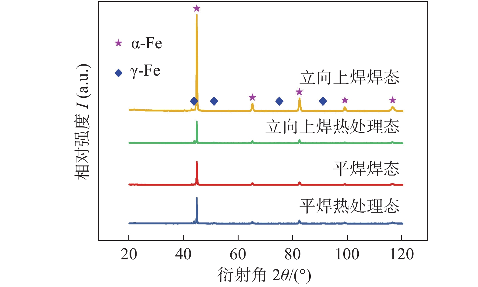
图 3 回火热处理态熔敷金属微观组织Figure 3. Microstructure of the as-tempered deposited metals. (a) weld in the flat welding position; (b) weld in the vertical-up welding position; (c) reheat zone in the flat welding position; (d) reheat zone in the vertical-up welding position超级马氏体不锈钢的奥氏体相在光学显微镜下无法分辨,于是通过X射线衍射的手段来表征奥氏体相并计算其相对含量,并测试了平焊焊态、平焊热处理态、立向上焊焊态、立向上焊热处理态4种状态的熔敷金属试样. 图4为4种试样的X射线衍射图谱,图谱中可标定出α-Fe和γ-Fe的衍射峰,Miller方法[10]可用来计算对应Cu靶辐射的α-Fe,γ-Fe两相的相对含量,计算公式如式(1)和式(2)所示.
$$ \mathop V\nolimits_{\text{γ}} + \mathop V\nolimits_{\text{α}} = 1 $$ (1) $$ \mathop V\nolimits_{\text{γ}} = \frac{{1.4\mathop I\nolimits_{\text{γ}} }}{{\mathop I\nolimits_{\text{α}} + 1.4\mathop I\nolimits_{\text{γ}} }} $$ (2) 式中:Vγ为γ-Fe相的体积分数;Vα为α-Fe相的体积分数;Iγ为γ-Fe相(111)晶面衍射线的累积强度;Iα为α-Fe相(110)晶面衍射线的累积强度.
表3为奥氏体相含量的XRD测量结果,两种焊接位置下熔敷金属中的奥氏体相含量相近,焊态熔敷金属中含有约1%的残余奥氏体,回火热处理态熔敷金属中含有约13%的逆变奥氏体. 经过回火热处理产生了较多含量的逆变奥氏体,这有利于焊缝金属韧性的恢复,热处理态试样的冲击韧性应该会比焊态试样的高. 结合图2和图3的微观组织分析结果,说明焊接位置的改变并没有影响超级马氏体不锈钢熔敷金属的组织类型,两种焊接位置下的微观组织无显著差异.
表 3 奥氏体含量XRD测定结果(体积分数, %)Table 3. XRD analysis results of austenite焊接位置 焊态组织
残余奥氏体热处理态组织
逆变奥氏体平焊 1.38 12.85 立向上焊 1.06 13.38 2.2 夹杂物特征
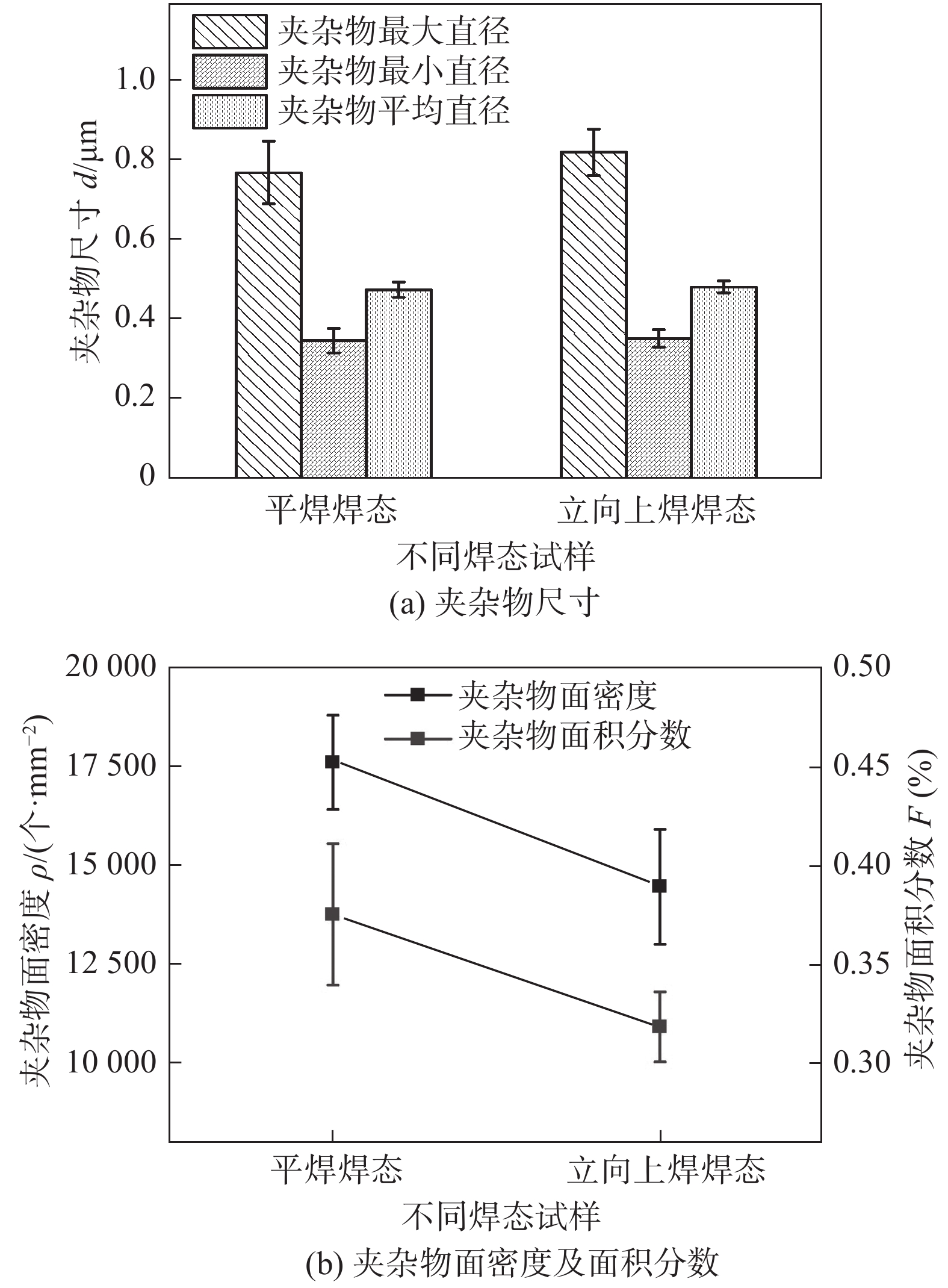
为了避免回火过程中析出的碳化物等第二相粒子对夹杂物的分析产生干扰,于是只对焊态熔敷金属的夹杂物进行了观察. 图5为夹杂物的尺寸、密度等特征分析结果. 试验中熔敷金属夹杂物的尺寸分布符合正态分布的特点,夹杂物的平均直径能够很好地用来表征夹杂物的尺寸特征,其中平焊位置夹杂物的平均直径为0.47 μm,立向上焊位置的为0.48 μm,立向上焊位置夹杂物的尺寸略高于平焊位置,总体上夹杂物直径都处于0.3 ~ 1 μm的范围内.平焊位置熔敷金属夹杂物的面密度平均值为17 629 个/mm2,相比立向上焊位置的14485 个/mm2增加了约22%,Foroozmehr等人[11]研究了同种类别的超级马氏体不锈钢熔敷金属的夹杂物特征,其夹杂物面密度的数值与文中的在同一数量级.立向上焊位置的热输入高于平焊位置,熔池金属在高温阶段停留时间延长,冷却速度降低,会促进夹杂物尺寸的增大[12],立向上焊位置熔池停留时间的延长有利于夹杂物浮出熔池表面,使得夹杂物数量减少. 另外,熔敷金属中夹杂物的来源,一是焊丝冶炼时产生的,二是在焊接过程中形成的,由于采用同一盘焊丝进行焊接,所以基本可以排除焊丝自身所含夹杂物的差异. 两种焊接位置下的熔滴过渡方式不同,平焊为射流过渡,而立向上焊为短路过渡,短路过渡的熔滴比表面积远小于射流过渡的熔滴,因此相比平焊位置,立向上焊位置的熔滴在过渡到熔池的过程中所受到的氧化作用较轻,带入熔敷金属中的夹杂物较少.综上所述,在立向上焊位置下焊接有利于降低熔敷金属中夹杂物的含量.
![]() 图 5 焊态熔敷金属夹杂物特征Figure 5. Inclusions characteristics of the as-welded deposited metals. (a) inclusions diameter size; (b) inclusions surface density and area fraction
图 5 焊态熔敷金属夹杂物特征Figure 5. Inclusions characteristics of the as-welded deposited metals. (a) inclusions diameter size; (b) inclusions surface density and area fraction2.3 熔敷金属冲击性能和显微硬度
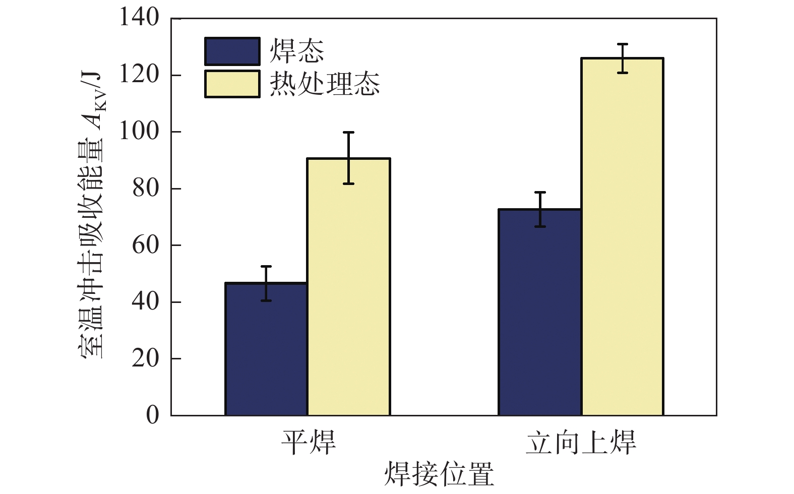
图6为熔敷金属的夏比V形缺口试样冲击测试结果. 平焊位置熔敷金属焊态和回火热处理态的室温冲击吸收能量平均值分别为47和91 J,立向上焊位置熔敷金属焊态和回火热处理态的室温冲击吸收能量平均值分别为73和126 J,相比平焊位置的熔敷金属,立向上焊焊态试样冲击吸收能量增加了26 J,回火热处理态试样冲击值增加了35 J. 由以上冲击测试结果可知,立向上焊位置明显提高了熔敷金属的室温冲击吸收能量.
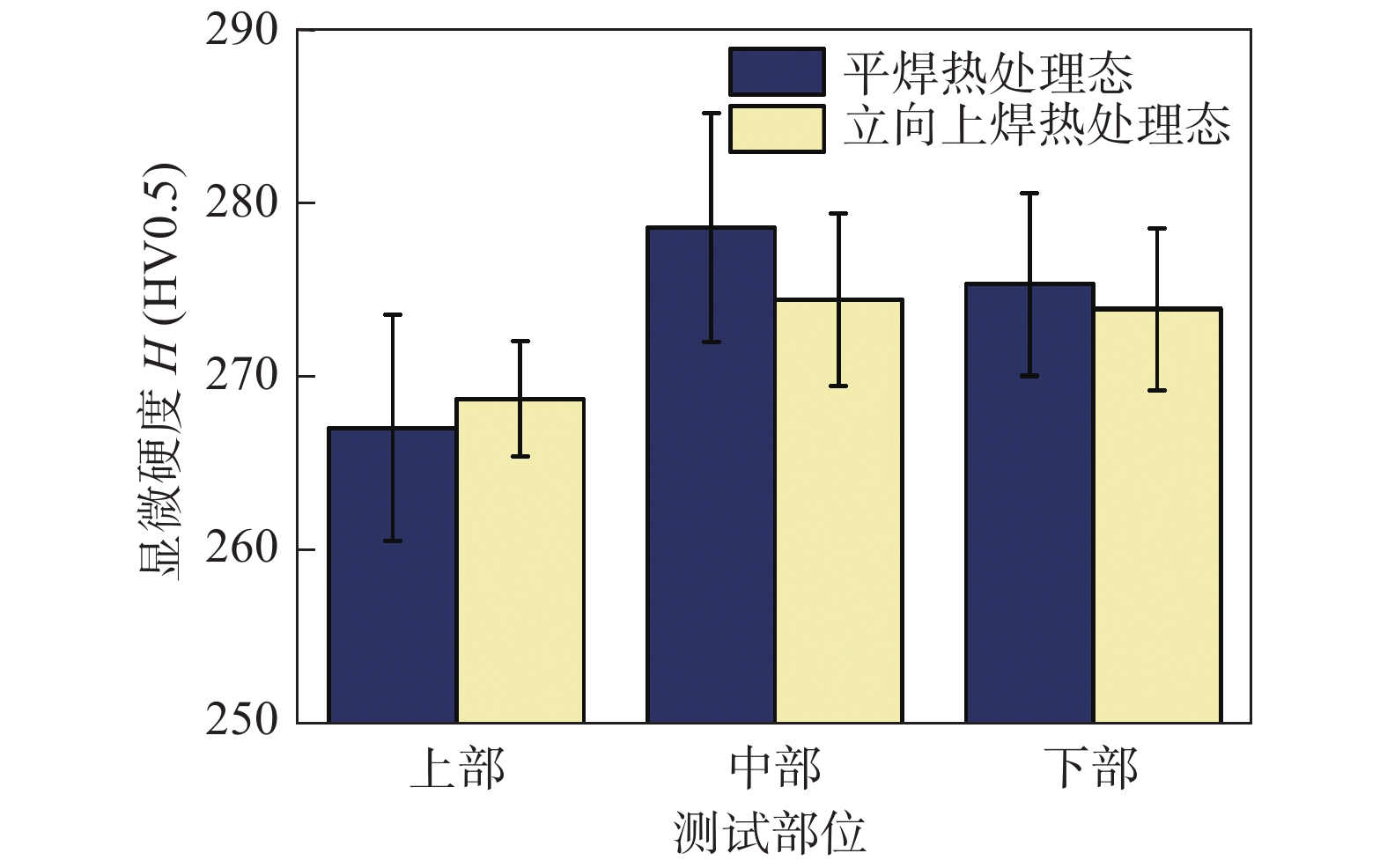
图7为平焊、立向上焊热处理态熔敷金属的上、中、下部位的显微硬度,显微硬度均处在260 ~ 290 HV的范围内. 平焊热处理态熔敷金属上部、中部、下部的显微硬度平均值分别为267,279,275 HV,立向上焊位置的分别为269,274,274 HV,平焊与立向上焊熔敷金属中、下部位的显微硬度均比上部区域增加了约10 HV,推测原因是多层多道焊的熔敷金属的中、下部位焊道受到上层焊道的热循环作用,产生了如图3c和图3d所示的重热区等轴晶,使得显微硬度值略有提高.
2.4 断口微观形貌分析
图8为冲击断口启裂区形貌,呈现出典型的韧窝形貌,该区域分布有大小不等的等轴或抛物线形韧窝,平焊、立向上焊冲击断口试样启裂区断裂特征无明显差异.
![]() 图 8 断口启裂区形貌Figure 8. Fracture morphologies of crack initiation region. (a) dimple of the as-welded deposited metals in the flat welding position; (b) dimple of the as-tempered deposited metals in the flat welding position; (c) dimple of the as-welded deposited metals in the vertical-up position; (d) dimple of the as-tempered deposited metals in the vertical-up position
图 8 断口启裂区形貌Figure 8. Fracture morphologies of crack initiation region. (a) dimple of the as-welded deposited metals in the flat welding position; (b) dimple of the as-tempered deposited metals in the flat welding position; (c) dimple of the as-welded deposited metals in the vertical-up position; (d) dimple of the as-tempered deposited metals in the vertical-up position图9为平焊焊态、平焊热处理态、立向上焊焊态和立向上焊热处理态试样冲击断口扩展区的微观形貌. 在4个试样冲击断口的扩展区均出现了尺寸不足0.5 mm × 0.5 mm的准解理区域,如图9a ~ 图9d所示,准解理面周围分布有大量的撕裂棱以及韧窝带,韧窝带区域的一些韧窝内和部分点状裂纹源内都存在有夹杂物颗粒. 另外,在平焊焊态试样和立向上焊热处理态试样的扩展区发现了少量的二次裂纹.扩展区绝大部分区域为图9e ~ 图9h所示的韧窝状断口形貌,其中焊态试样扩展区为小而浅的韧窝,而热处理态试样扩展区的韧窝表现为大而深的特点,热处理态试样的韧性要优于焊态试样. 立向上焊冲击试样的断口扩展区韧窝尺寸大于平焊试样,且断口表面凸凹不平,表现出更优异的韧性断裂特征,冲击断口的形貌变化与冲击吸收能量之间的变化趋势相一致. 韧窝底部分布有大量的球形夹杂物,对图9e和图9f所示断口韧窝中的夹杂物进行统计,夹杂物的直径基本都小于1 μm,立向上焊夹杂物的数量少于平焊,与金相抛光表面夹杂物的分析结果表现出相同的规律.通过扫描电子显微镜-能谱仪的手段来判断这些第二相粒子的种类,其中图9e ~ 图9h白色箭头所指处为EDS分析的位置,结果如表4所示,Cr元素的含量和基体接近,认为这些第二相粒子不是回火过程中析出的富Cr碳化物等沉淀物,而是含有Si,Mn,Al等元素的氧化物.
![]() 图 9 断口扩展区形貌Figure 9. Fracture morphologies of crack propagation region of deposited metals. (a) quasi-cleavage of the as-welded deposited metals in the flat welding position; (b) quasi-cleavage of the as-welded deposited metals in the vertical-up welding position; (c) quasi-cleavage of the as-tempered deposited metals in the flat welding position; (d) quasi-cleavage of the as-tempered deposited metals in the vertical-up welding position; (e) dimple of the as-welded deposited metals in the flat welding position; (f) dimple of the as-welded deposited metals in the vertical-up position; (g) dimple of the as-tempered deposited metals in the flat welding position; (h) dimple of the as-tempered deposited metals in the vertical-up position表 4 夹杂物EDS分析结果(质量分数,%)Table 4. EDS analysis results of inclusions
图 9 断口扩展区形貌Figure 9. Fracture morphologies of crack propagation region of deposited metals. (a) quasi-cleavage of the as-welded deposited metals in the flat welding position; (b) quasi-cleavage of the as-welded deposited metals in the vertical-up welding position; (c) quasi-cleavage of the as-tempered deposited metals in the flat welding position; (d) quasi-cleavage of the as-tempered deposited metals in the vertical-up welding position; (e) dimple of the as-welded deposited metals in the flat welding position; (f) dimple of the as-welded deposited metals in the vertical-up position; (g) dimple of the as-tempered deposited metals in the flat welding position; (h) dimple of the as-tempered deposited metals in the vertical-up position表 4 夹杂物EDS分析结果(质量分数,%)Table 4. EDS analysis results of inclusions试样状态 O C Si Mn Cr Ni Mo Al Fe 平焊焊态 10.93 6.27 4.22 4.32 11.51 3.10 0.49 0.16 58.62 平焊热处理态 13.98 3.02 5.44 5.25 11.65 2.71 0.38 0.35 56.79 立向上焊焊态 22.68 4.89 8.66 10.17 9.63 1.91 — 1.05 39.49 立向上焊热处理态 5.55 1.53 3.31 9.31 13.65 2.20 0.08 0.33 62.96 2.5 立向上焊提高超级马氏体不锈钢熔敷金属韧性的讨论
相组成及其含量都会影响材料的性能,逆变奥氏体是超级马氏体不锈钢中重要的韧化相,以往研究表明[4,13-14],逆变奥氏体含量的增加会提高超级马氏体不锈钢的冲击韧性,然而在该研究中,立向上焊并没有造成组织中逆变奥氏体含量的增加,两种焊接工艺下熔敷金属微观组织的类型相似.
使用MAG焊工艺不可避免地会造成熔敷金属增氧的问题,焊接时保护气体中的CO2分解产生的O与焊丝中的合金元素反应会形成氧化物夹杂. 在试样断裂过程中,氧化物夹杂与金属基体之间的界面可能会形成裂纹源,夹杂物的密度、尺寸等特征对材料的韧性有着重要的影响. 超级马氏体不锈钢MAG焊熔敷金属中氧化物的类型主要是以Si-Mn-O和Si-Mn-Al-O为主的复合氧化物,氧化物数量的增加会降低材料的冲击韧性[7,15]. 在试验中发现立向上焊熔敷金属中夹杂物的面密度小于平焊,这会在一定程度上改善熔敷金属的冲击性能.
焊缝组织的形态和大小也会影响熔敷金属的冲击韧性,柱状晶的尺寸和比例越大,焊缝的冲击韧性越低,在多层多道焊工艺中,焊接热循环作用有可能会细化焊缝的柱状晶组织,从而提高焊缝金属的韧性[16-17],上述图3c和图3d所示的平焊和立向上焊的层道间重热区组织表现出等轴晶的形态,说明先焊焊道的焊缝组织柱状晶在后焊焊道的再热作用下,发生重结晶而转变为等轴晶.对于平焊和立向上焊焊缝组织的柱状晶和等轴晶是否存在差别,还有待进一步深入的研究.
3. 结论
(1)与平焊相比,立向上焊焊接工艺能显著提高超级马氏体不锈钢焊丝熔敷金属的韧性,经590 ℃ × 8 h焊后热处理室温冲击吸收能量可以达到120 J以上.两种焊接位置下熔敷金属的断裂形式均为韧性断裂,立向上焊熔敷金属断口扩展区的韧窝尺寸更大.
(2)平焊、立向上焊熔敷金属的微观组织类型相似,焊态组织均为淬火板条马氏体和少量的残余奥氏体、δ-Fe;回火热处理态组织均为回火板条马氏体、逆变奥氏体和δ-Fe.
(3)平焊、立向上焊熔敷金属中的夹杂物为含有Mn,Si,Al等元素的复合氧化物,平焊位置熔敷金属夹杂物的面密度比立向上焊位置增加了22%左右,夹杂物数量的减少是立向上焊位置熔敷金属韧性提高的原因之一.
-
![]()
图 2 焊态熔敷金属微观组织
Figure 2. Microstructure of the as-welded deposited metals. (a) weld in the flat welding position; (b) weld in the vertical-up welding position; (c) reheat zone in the flat welding position; (d) reheat zone in the vertical-up welding position
![]()
图 3 回火热处理态熔敷金属微观组织
Figure 3. Microstructure of the as-tempered deposited metals. (a) weld in the flat welding position; (b) weld in the vertical-up welding position; (c) reheat zone in the flat welding position; (d) reheat zone in the vertical-up welding position
![]()
图 5 焊态熔敷金属夹杂物特征
Figure 5. Inclusions characteristics of the as-welded deposited metals. (a) inclusions diameter size; (b) inclusions surface density and area fraction
![]()
图 8 断口启裂区形貌
Figure 8. Fracture morphologies of crack initiation region. (a) dimple of the as-welded deposited metals in the flat welding position; (b) dimple of the as-tempered deposited metals in the flat welding position; (c) dimple of the as-welded deposited metals in the vertical-up position; (d) dimple of the as-tempered deposited metals in the vertical-up position
![]()
图 9 断口扩展区形貌
Figure 9. Fracture morphologies of crack propagation region of deposited metals. (a) quasi-cleavage of the as-welded deposited metals in the flat welding position; (b) quasi-cleavage of the as-welded deposited metals in the vertical-up welding position; (c) quasi-cleavage of the as-tempered deposited metals in the flat welding position; (d) quasi-cleavage of the as-tempered deposited metals in the vertical-up welding position; (e) dimple of the as-welded deposited metals in the flat welding position; (f) dimple of the as-welded deposited metals in the vertical-up position; (g) dimple of the as-tempered deposited metals in the flat welding position; (h) dimple of the as-tempered deposited metals in the vertical-up position
表 1 MAG焊焊接工艺参数
Table 1 MAG welding process parameters
焊接位置 焊接电流I/A 电弧电压U/V 焊接速度ν/(mm·min−1) 保护气体 平均热输入E/(kJ·cm−1) 平焊 220 ~ 240 28 ~ 30 250 Ar + 3%CO2 16 立向上焊 160 ~ 180 20 ~ 22 100 ~ 120 Ar + 3%CO2 19  下载: 导出CSV
表 2 熔敷金属化学成分(质量分数,%)
Table 2 Chemical compositions of deposited metals
焊接位置 C Si Mn S P Cr Ni Mo O Fe 平焊 0.032 0.47 0.64 0.0025 0.0051 12.49 4.44 0.50 0.038 余量 立向上焊 0.028 0.51 0.65 0.0022 0.0040 12.21 4.37 0.50 0.031 余量
下载: 导出CSV
表 3 奥氏体含量XRD测定结果(体积分数, %)
Table 3 XRD analysis results of austenite
焊接位置 焊态组织
残余奥氏体热处理态组织
逆变奥氏体平焊 1.38 12.85 立向上焊 1.06 13.38
下载: 导出CSV
表 4 夹杂物EDS分析结果(质量分数,%)
Table 4 EDS analysis results of inclusions
试样状态 O C Si Mn Cr Ni Mo Al Fe 平焊焊态 10.93 6.27 4.22 4.32 11.51 3.10 0.49 0.16 58.62 平焊热处理态 13.98 3.02 5.44 5.25 11.65 2.71 0.38 0.35 56.79 立向上焊焊态 22.68 4.89 8.66 10.17 9.63 1.91 — 1.05 39.49 立向上焊热处理态 5.55 1.53 3.31 9.31 13.65 2.20 0.08 0.33 62.96
下载: 导出CSV
-
[1] Thibault D, Gagnon M, Godin S. Bridging the gap between metallurgy and fatigue reliability of hydraulic turbine runners[C]// 27th IAHR Symposium on Hydraulic Machinery and Systems. IOP Conference Series: Earth and Environmental Science. Montreal, Canada, 2014: 012019.
[2] Liu Y, Ye D, Yong Q, et al. Effect of heat treatment on microstructure and property of Cr13 super martensitic stainless steel[J]. Journal of Iron and Steel Research International, 2011, 18(11): 60 − 66. doi: 10.1016/S1006-706X(11)60118-0
[3] Tavares S S M, Almeida B B, Corrêa D A L, et al. Failure of super 13Cr stainless steel due to excessive hardness in the welded joint[J]. Engineering Failure Analysis, 2018, 91: 92 − 98. doi: 10.1016/j.engfailanal.2018.04.018
[4] Wu S, Wang D, Chen Z, et al. Enhanced toughness of Fe-12Cr-5.5Ni-Mo-deposited metals through formation of fine reversed austenite[J]. Journal of Materials Science, 2018, 53(22): 15679 − 15693. doi: 10.1007/s10853-018-2718-1
[5] Sarafan S, Wanjara P, Champliaud H, et al. Characteristics of an autogenous single pass electron beam weld in thick gage CA6NM steel[J]. International Journal of Advanced Manufacturing Technology, 2015, 78(9-12): 1523 − 1535. doi: 10.1007/s00170-014-6713-7
[6] Aleksandr S, Oleg P, Vladimir L, et al. Influence of shielding gas and non-consumable electrode configuration on weld formation[J]. China Welding, 2021, 30(4): 17 − 24.
[7] 杜兵, 孙凤莲, 徐玉君, 等. 焊接方法对超低碳马氏体不锈钢焊丝熔敷金属冲击韧性的影响[J]. 焊接学报, 2014, 35(8): 1 − 4. Du Bing, Sun Fenglian, Xu Yujun, et al. Effect of welding methods on impact toughness of ultra-low carbon martensitic stainless steel welding wire deposited metal[J]. Transactions of the China Welding Institution, 2014, 35(8): 1 − 4.
[8] 裴冲, 王东坡, 邓彩艳, 等. 不同焊接位置海洋平台用钢焊缝金属低温断裂韧性[J]. 焊接学报, 2016, 37(3): 111 − 114. Pei Chong, Wang Dongpo, Deng Caiyan, et al. Low temperature fracture toughness of welding metal of offshore platform steel in different welding positions[J]. Transactions of the China Welding Institution, 2016, 37(3): 111 − 114.
[9] 牟淑坤, 栗卓新, 张飞虎, 等. 焊接位置对药芯焊丝熔敷金属低温冲击韧性的影响[J]. 机械工程材料, 2013, 37(3): 37 − 41. Mu Shukun, Li Zhuoxin, Zhang Feihu, et al. Effect of welding position on low temperature impact toughness of deposited metal of flux cored wire[J]. Materials for Mechanical Engineering, 2013, 37(3): 37 − 41.
[10] Liu Z, Gao Z, Lv C, et al. Research on the correlation between impact toughness and corrosion performance of Cr13 super martensitic stainless steel under deferent tempering condition[J]. Materials Letters, 2021, 283: 128791. doi: 10.1016/j.matlet.2020.128791
[11] Foroozmehr F, Bocher P. On the ductile rupture of 13%Cr-4%Ni martensitic stainless steels[J]. International Journal of Fracture, 2020, 224(1): 67 − 82. doi: 10.1007/s10704-020-00446-2
[12] 巴凌志, 王东坡, 张智, 等. 热输入对海工用钢不同合金系焊缝金属韧性的影响[J]. 焊接学报, 2020, 41(6): 42 − 47. doi: 10.12073/j.hjxb.20190623002 Ba Lingzhi, Wang Dongpo, Zhang Zhi, et al. Effect of welding heat input on toughness of different alloys weld metal in ocean engineering steel[J]. Transactions of the China Welding Institution, 2020, 41(6): 42 − 47. doi: 10.12073/j.hjxb.20190623002
[13] Qin B, Wang Z, Sun Q. Effect of tempering temperature on properties of 00Cr16Ni5Mo stainless steel[J]. Materials Characterization, 2008, 59(8): 1096 − 1100. doi: 10.1016/j.matchar.2007.08.025
[14] Zou D, Han Y, Zhang W, et al. Influence of tempering process on mechanical properties of 00Cr13Ni4Mo supermartensitic stainless steel[J]. Journal of Iron and Steel Research International, 2010, 17(8): 50 − 54. doi: 10.1016/S1006-706X(10)60128-8
[15] 于航, 侴树国, 王慧源, 等. 氧对00Cr13Ni5Mo熔敷金属组织和韧性的影响[J]. 焊接学报, 2014, 35(6): 109 − 112. Yu Hang, Chou Shuguo, Wang Huiyuan, et al. Effect of oxygen on toughness and microstructure of 00Cr13Ni5Mo deposited metal[J]. Transactions of the China Welding Institution, 2014, 35(6): 109 − 112.
[16] 彭杏娜, 彭云, 彭先宽, 等. 多层多道TIG焊对高强钢焊缝组织和韧性的影响[J]. 机械工程学报, 2017, 53(18): 106 − 112. doi: 10.3901/JME.2017.17.106 Peng Xingna, Peng Yun, Peng Xiankuan, et al. Influence of multi-layer and multi-pass TIG welding process on the high strength weld metal microstructure and toughness[J]. Journal of Mechanical Engineering, 2017, 53(18): 106 − 112. doi: 10.3901/JME.2017.17.106
[17] 安同邦, 田志凌, 单际国, 等. 焊接方法对1 000 MPa级熔敷金属组织及力学性能的影响[J]. 焊接学报, 2015, 36(11): 101 − 104. An Tongbang, Tian Zhiling, Shan Jiguo, et al. Effect of welding methods on microstructure and mechanical properties of 1 000 MPa grade deposited metal[J]. Transactions of the China Welding Institution, 2015, 36(11): 101 − 104.


计量
- 文章访问数: 320
- HTML全文浏览量: 29
- PDF下载量: 34
