
Study on laser edge sealing welding of aluminum alloy based on response surface method
-
摘要: 采用响应曲面法对2A12铝合金激光封边焊接进行了研究,结果表明,2A12铝合金激光封边焊接焊缝几何特征的主要影响因素依次为离焦量、焊接速度和激光功率. 2A12铝合金激光封边焊缝的显微组织自熔合线向上依次呈现较粗大的胞状树枝晶、细小的胞状树枝晶和等轴晶. 在熔合线附近和过渡区域,强化相沿晶界分布;而在焊缝中心区域,还有少量强化相分布于晶粒内部. 与正离焦量相比,负离焦量时,焊缝的晶粒尺寸较大并且镁元素烧损也更加严重,使得强化相CuMgAl2含量降低,导致强化效果减弱和焊缝硬度降低. 离焦量为 + 2 mm和−2 mm时,激光封边焊接的气密性均良好.Abstract: Response surface methodology was used to study the laser edge sealing welding of 2A12 aluminum alloy. The results showed that the main influencing factors of the geometrical characteristics of 2A12 aluminum alloy were defocusing amount, welding speed and laser power. From fusion line to weld center, the microstructure of 2A12 aluminum alloy laser edge sealing weld were coarse cellular dendrites, fine cellular dendrites and equiaxed crystals. The strengthening phases distributed along the grain boundary near the fusion line and in the transition region. At the center of weld, a small amount of strengthening phases distributed in the grain. Compared with the positive defocusing amount, the grain size of weld was larger and the magnesium element burned more seriously at the negative defocusing amount, which reduced the content of strengthening phase CuMgAl2 and led to the weakening of strengthening effect and the reduction of weld microhardness. When defocusing amount were + 2 mm and −2 mm, both of the air tightness of laser edge sealing welding were good.
-
0. 序言
封边技术常见于电子产品领域,主要包括环氧树脂密封、机械固定以及焊接等. 激光焊接的加热范围小,焊缝和热影响区较窄,接头性能优良;残余应力和焊接变形小, 可以实现高精度焊接. 随着激光焊接技术的发展及其独特的优点而被广泛应用于电子产品中的铜、铝合金以及不锈钢等材料[1-4].
Liu 等人[5]利用激光焊接粉末冶金制备的高硅铝基复合材料,得到了高气密性的封边焊缝,氦泄露检测结果与采用传统的Kovar合金和纯铝合金封装的效果相近但该材料的力学性能远优于上述两种材料,该结果证明了采用激光封边铝基材料的可行性. 周明智等人[6]对高硅铝合金壳体和盖板进行了脉冲激光封焊试验,通过合理地设置激光焊接参数和调整激光脉冲波形,可有效避免焊接过程中的裂纹缺陷. 王成等人[7]通过正交试验方法研究了焊接参数对铝合金壳体气密性的影响,得到了影响激光封焊效果的规律,确定了最佳的工艺参数,焊后气密性可达6.5 × 10⁻¹⁰ Pa·m3/s. 聂要要等人[8]进行了正交试验分析,研究了激光功率、焊接速度和离焦量等工艺参数对焊缝形貌的影响规律,证明了激光封边焊的可靠性.
对于铝合金的封边焊接,目前的研究主要基于电子产品的背景. 而其在航空航天结构的制备中几乎未见较为成熟的研究. 通过采用响应曲面法对航空航天中常用的2A12铝合金的激光封边焊接进行了研究,并从焊缝几何特征以及组织和性能等方面分析了焊接的工艺参数对焊接质量的影响.
1. 试验方法
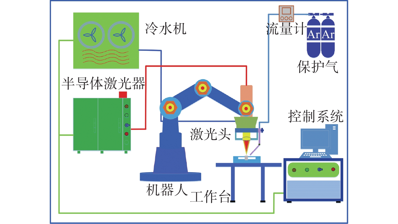
激光焊接试验平台的示意图如图1所示,该试验平台主要由半导体激光器、焊接机器人及控制系统等组成. 其中半导体激光器的最大输出功率为5 kW,波长为915 nm,光芯直径为800 μm. 由于铝合金属于高反射率材料,为了防止损坏激光头,在焊接时将激光头倾斜15°. 采用Ar气保护焊接区域来避免焊缝氧化.
作为中高强度Al-Cu-Mg 系固溶时效强化的铝合金[9]. 2A12铝合金在飞行器的蒙皮、隔框、翼肋、壁板等均得到广泛应用[10]. 试验所用铝合金的尺寸为120 mm × 25 mm × 2 mm, 成分如表1所示. 母材的金相照片如图2所示,它的组织由白色的α-Al基体和黑色的Al2CuMg第二相组成[11].
表 1 2A12铝合金的化学成分(质量分数,%)Table 1. Chemical compositions of the 2A12 aluminum alloyCu Mg Mn Fe Si Zn Ti Ni Al 4.12 1.47 0.65 0.31 0.23 0.15 0.03 0.01 余量 采用激光自熔焊的方法对2A12铝合金进行封边焊接,将激光功率、焊接速度、离焦量和保护气体流量等4种因素作为响应曲面法的研究因素. 通过线性变换后以−1,0,1分别代表其低、中及高水平. 各因素的取值范围分别为:激光功率2 750 ~ 3 250 W,焊接速度8 ~ 12 mm/s,离焦量−2 ~ +2 mm,保护气体流量10 ~ 20 L/min,如表2所示.
表 2 因素编码及水平表Table 2. Factor coding and level table水平 激光功率 P/W 焊接速度 v/( mm·s−1) 离焦量 df /mm 保护气体流量 Q/(L·min−1) −1 2 750 8 −2 10 0 3 000 10 0 15 1 3 250 12 +2 20 焊接试验完成后,使用电火花线切割机沿着垂直于焊缝的方向切取金相试样并镶嵌,然后依次用400号 ~ 5 000号的SiC水磨砂纸进行磨抛,再用颗粒度为1.0 μm的金刚石抛光剂配合抛光布进行抛光至试样表面无划痕. 使用Keller试剂对抛光后的试样进行腐蚀,腐蚀后用水和酒精反复冲洗并吹干. 腐蚀完成后,采用OLYMPUS光学数码显微镜对焊缝的横截面进行分析,得到焊缝的几何尺寸. 采用蔡司场发射扫描电子显微镜对接头进行微观组织观察,并结合配套的能谱仪对不同微区进行EDS分析,得到不同区域的成分组成. 采用手动转塔显微硬度计对封边焊接接头进行硬度表征,加载力为1.96 N,加载时间为10 s. 采用盛水试验对激光封边焊接接头进行气密性测试.
2. 试验结果及分析
2.1 焊缝几何特征
试验设计了4因素3水平的响应曲面分析试验,共有29个试验点. 响应曲面设计方案与试验结果如表3所示.
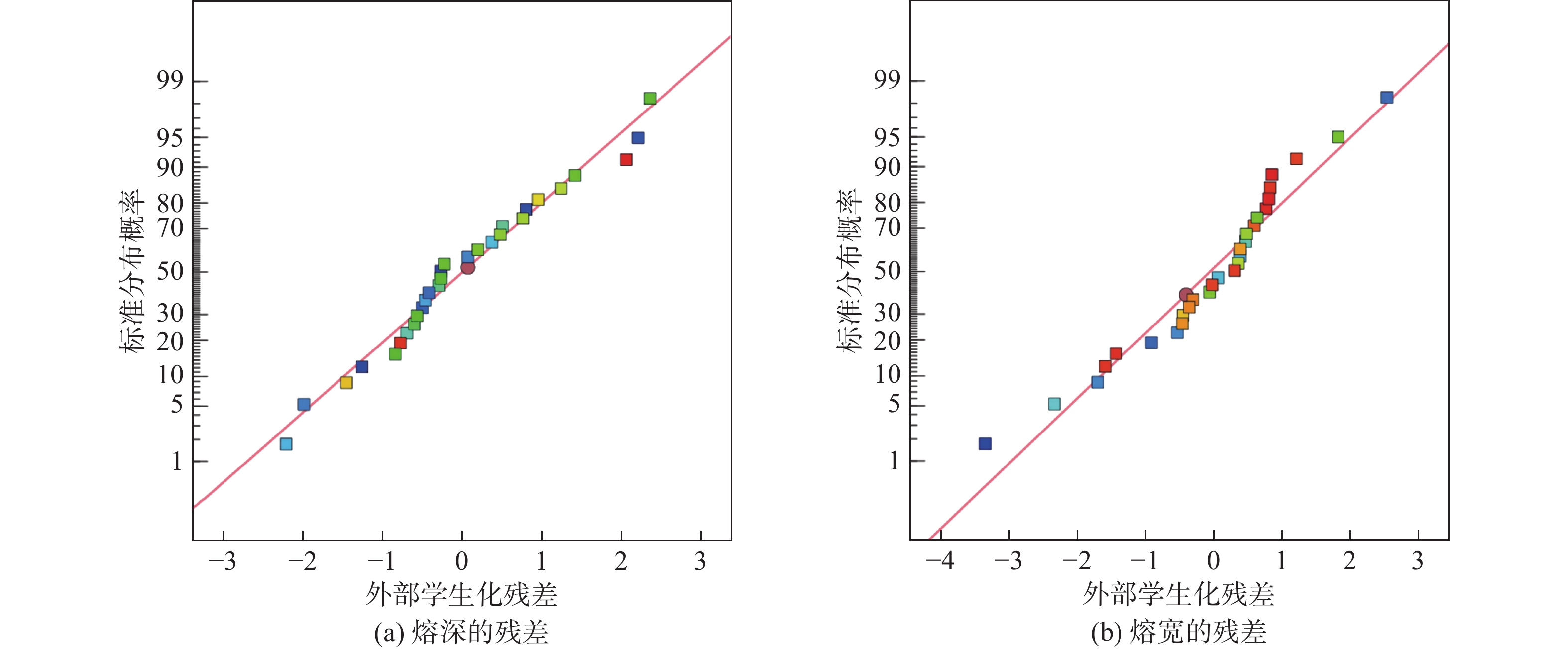
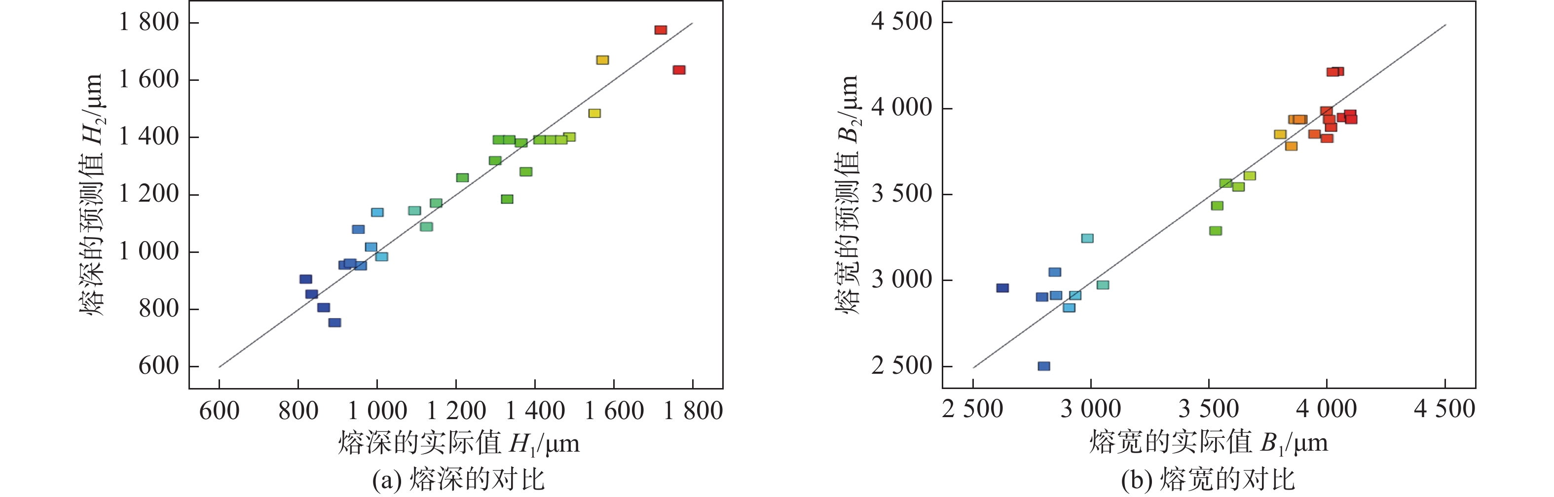
表 3 响应曲面的设计与结果Table 3. Design and results of response surface序号 激光功率P/W 焊接速度 v/(mm·s−1) 离焦量 df/mm 保护气体流量Q/(L·min−1) 熔深H/μm 熔宽B/μm 1 2 750 8 0 15 1 330.249 3 944.42 2 3 250 8 0 15 1 552.286 4 064.147 3 2 750 12 0 15 1 012.336 3 049.104 4 3 250 12 0 15 1 095.403 3 533.258 5 3 000 10 −2 10 1 216.942 3 997.757 6 3 000 10 2 10 919.334 2 905.551 7 3 000 10 −2 20 1 766.443 4 095.258 8 3 000 10 2 20 893.464 2 932.171 9 2 750 10 0 10 835.062 2 791.057 10 3 250 10 0 10 1 377.999 3 846.654 11 2 750 10 0 20 1 111.183 3 670.094 12 3 250 10 0 20 1 150.340 3 526.237 13 3 000 8 −2 15 1 572.066 4 042.613 14 3 000 12 −2 15 1 488.453 4 014.622 15 3 000 8 2 15 953.094 3 568.991 16 3 000 12 2 15 865.469 3 065.678 17 2 750 10 −2 15 1 365.455 3 995.184 18 3 250 10 −2 15 1 719.999 4 021.145 19 2 750 10 2 15 958.764 2 750.043 20 3 250 10 2 15 985.532 2 983.055 21 3 000 8 0 10 1 125.832 3 622.271 22 3000 12 0 10 932.438 2 845.015 23 3 000 8 0 20 1 300.346 3 799.699 24 3 000 12 0 20 819.857 2 624.423 25 3 000 10 0 15 1 251.297 3 866.230 26 3 000 10 0 15 1 467.777 4 007.034 27 3 000 10 0 15 1 309.242 3 960.410 28 3 000 10 0 15 1 335.353 2 970.695 29 3 000 10 0 15 1 746.134 4 034.367 对上述2个模型进行检验,其残差分布及实际值与预测值的对比分别如图3和图4所示. 从图3中可以看出,残差分布于45°线附近,说明模型的稳定性较高,在给定范围内具有较高的可信性. 从图4中可以看出,各数据点基本分布于45°线附近,实际值与预测值较为接近,说明上述2个模型的可靠性较高. 对2个模型进行方差分析,其诊断结果分别如表4和表5所示. 当P值处于一定的范围时则能表示该方差来源在响应曲面模型中的显著性. P<0.05为显著;P<0.01为高度显著;P<0.001为极显著. 基于此可较为直观的判断出各因素对熔深和熔宽的显著性,最终明确工艺参数对封边焊接接头的影响情况.
![]() 图 3 模型的残差分布Figure 3. Residual distribution of the model. (a) the residuals of Penetration; (b) the residuals of weld width
图 3 模型的残差分布Figure 3. Residual distribution of the model. (a) the residuals of Penetration; (b) the residuals of weld width![]() 图 4 实际值与预测值的对比Figure 4. Comparison of actual and predicted values. (a) the comparison of penetration; (b) the comparison of weld width表 4 熔深的响应曲面诊断结果Table 4. Penetration value of response surface diagnostic results
图 4 实际值与预测值的对比Figure 4. Comparison of actual and predicted values. (a) the comparison of penetration; (b) the comparison of weld width表 4 熔深的响应曲面诊断结果Table 4. Penetration value of response surface diagnostic results方差来源 平方和U 自由度f 均方u 检验值F 显著性P 模型 1.948 × 10⁶ 14 1.392 × 10⁵ 11.67 < 0.000 1 激光功率 1.583 × 10⁵ 1 1.583 × 10⁵ 13.28 0.002 7 焊接速度 2.187 × 10⁵ 1 2.187 × 10⁵ 18.35 0.000 8 离焦量 1.052 × 10⁶ 1 1.052 × 10⁶ 88.29 < 0.000 1 保护气体流量 22 917.94 1 22 917.94 1.92 0.187 2 残差 1.669 × 10⁵ 14 11 919.18 失拟项 1.483 × 10⁵ 10 14 833.90 3.20 0.136 6 纯差 18 529.50 4 4 632.37 R2 0.921 1 R2Adj 0.842 2 表 5 熔宽的响应曲面诊断结果Table 5. weld width value of response surface diagnostic results方差来源 平方和U 自由度f 均方u 检验值F 显著性P 模型 6.539 × 10⁶ 14 4.671 × 10⁵ 10.75 < 0.000 1 激光功率 2.337 × 10⁵ 1 2.337 × 10⁵ 5.38 0.036 0 焊接速度 1.453 × 10⁶ 1 1.453 × 10⁶ 33.45 < 0.000 1 离焦量 3.128 × 10⁶ 1 3.128 × 10⁶ 72.01 < 0.000 1 保护气体流量 34 088.33 1 34 088.33 0.78 0.390 7 残差 6.174 × 10⁵ 14 44 096.50 失拟项 5.658 × 10⁵ 10 56 584.04 5.34 0.060 4 纯差 42 412.75 4 10 603.19 R2 0.914 9 R2Adj 0.829 8 据表4和表5所示,2个模型整体具有极显著性而失拟项为不显著性,另外,复相关系数R与RAdj均大于0.9,说明模型的可信度较高,可以进行后续分析. 在4种影响因素中,激光功率对熔深的影响为高度显著,焊接速度和离焦量为极显著,保护气体流量则体现为不显著性;在对熔宽的影响中,激光功率为显著性,焊接速度和离焦量呈现极显著性,而气流量呈现不显著性.
使用Design-Expert软件对响应曲面模型进行分析后得到3D响应曲面图,在此基础上研究各主要工艺参数对接头的影响. 当保护气体流量为15 L/min时,在不同离焦量下激光功率和焊接速度对接头的交互影响如图5和图6所示. 从图5中可以看出,处于负离焦量时,激光功率与焊接速度对熔深的影响要比零焦和正离焦量时显著,体现为3D曲面图坡度较大. 从图6中可以看出,当负离焦量为−2 mm时,熔宽在一定的参数范围内中可以维持在4 000 μm左右,即约等于2倍母材的宽度;当离焦量为+2 mm时,熔深对激光功率以及焊接速度的改变较为敏感,体现为3D曲面的下降幅度较大,最低达到2 000 μm左右,说明接头的熔宽较小. 另外,不管离焦量为−2 mm,0 mm还是+2 mm,随着激光功率增加以及焊接速度降低,熔深与熔宽均呈现增加趋势,母材熔化量较多,接头区域较大.
![]() 图 5 不同离焦量下激光功率和焊接速度对熔深的影响Figure 5. Influence of laser power and welding speed on penetration value under different defocusing amounts. (a) −2 mm; (b) 0 mm; (c) +2 mm
图 5 不同离焦量下激光功率和焊接速度对熔深的影响Figure 5. Influence of laser power and welding speed on penetration value under different defocusing amounts. (a) −2 mm; (b) 0 mm; (c) +2 mm![]() 图 6 不同离焦量下激光功率和焊接速度对熔宽的影响Figure 6. Influence of laser power and welding speed on weld width value under different defocusing amounts. (a) −2 mm; (b) 0 mm; (c) +2 mm
图 6 不同离焦量下激光功率和焊接速度对熔宽的影响Figure 6. Influence of laser power and welding speed on weld width value under different defocusing amounts. (a) −2 mm; (b) 0 mm; (c) +2 mm基于上述分析,离焦量对于接头的影响较为显著. 在不同的离焦量下,接头的熔深与熔宽差异较为明显. 当离焦量为−2 mm时,熔深与熔宽整体处于较高的水平;当离焦量为0 mm时,熔深与熔宽整体呈现下降的趋势;当离焦量为+2 mm时,熔深与熔宽处于低水平的状态. 熔深与熔宽决定了焊缝横截面的面积大小,横截面的面积越大,则焊缝的力学性能相对更高. 因此,应该采用负离焦量进行铝合金的封边焊接.
2.2 接头显微组织分析
离焦量是对接头的几何尺寸影响最显著的因素,故选取激光功率3 250 W,焊接速度为10 mm/s,保护气体流量为15 L/min,离焦量分别为+2 mm和−2 mm的接头进行显微组织分析.
图7a和7b分别为正离焦量和负离焦量下熔合线附近的组织,由于激光热源的作用,使得靠近熔合线附近的母材组织发生改变,形成热影响区. 当离焦量为负时,光束在接头内部聚焦,对接头的热作用增加,使得受到焊接过程影响的母材区域增加,即热影响区变宽. 在激光焊接过程中,靠近熔合线附近的熔池区域受到周围大体积母材金属的冷却作用而形成较大的温度梯度,导致在熔合线附近形成了树枝晶. 当离焦量为负时,相同热输入下,激光对接头的热作用增加,熔池高温停留时间较长,给予树枝晶较多的生长时间,树枝晶较为粗大. 但由于温度分布不均匀以及热扩散导致的最优结晶取向与熔池某处瞬时温度梯度的最大方向不同,使得部分树枝晶呈现偏离熔合线垂直方向生长甚至停止生长的情况. 随着熔合区树枝晶的生长,会使大量的溶质从晶体中排出. 另外,随着结晶过程不断进行,温度梯度逐渐降低而结晶速度逐渐增大,使得胞状树枝晶变得较为细小. 除从晶体中排出的溶质外,熔池中未熔化的质点杂质也会促进非均匀形核,正在生长的树枝晶遇到新的晶核后便停止生长,与前述条件共同促进等轴晶形成,最终由细小的胞状树枝晶逐渐过渡为焊缝中心区域的以等轴晶为主的组织,如图7c和7d所示. 与熔合线附近的组织类似,离焦量为−2 mm时,等轴晶的晶粒尺寸较大. 离焦量为+2 mm时熔池受激光热作用较小,晶粒的生长时间变短,故而在焊缝中心处形成细小的等轴晶组织.
![]() 图 7 不同离焦量下的金相图片Figure 7. Metallographic pictures under different defocusing amounts. (a) defocusing amount of +2 mm near the fusion line; (b) defocusing amount of −2 mm near the fusion line; (c) defocusing amount of +2 mm at the center of weld; (d) defocusing amount of −2 mm at the center of weld
图 7 不同离焦量下的金相图片Figure 7. Metallographic pictures under different defocusing amounts. (a) defocusing amount of +2 mm near the fusion line; (b) defocusing amount of −2 mm near the fusion line; (c) defocusing amount of +2 mm at the center of weld; (d) defocusing amount of −2 mm at the center of weld图8a和8b分别为正离焦量和负离焦量下熔合线附近的组织,该区域的强化相沿晶界分布. 图8c和8d分别为正离焦量和负离焦量下熔合线附近向焊缝中心过渡区域的显微组织,该区域的强化相同样沿晶界分布,晶粒生长方向性较为明显,此处主要为胞状树枝晶. 对晶界位置A以及基体区域B进行EDS分析,结果如表6所示,其中A区域的点扫结果根据有关文献的研究[12],分布于晶界处的强化相可能为低熔点共晶α-Al固溶体 + CuAl2(θ)或α-Al 固溶体 + CuMgAl2(S)或α + θ + S. 基体区域B位置的点扫结果,该区域为α-Al固溶体. 如图8e和8f所示分别为正离焦量和负离焦量下焊缝中心处的显微组织,强化相主要呈现颗粒状分布于晶界处,少量分布于晶粒内部,此处主要为等轴晶.
![]() 图 8 不同离焦量下的微观组织Figure 8. Microstructure under different defocusing amounts. (a) defocusing amount of +2 mm near the fusion line; (b) defocusing amount of −2 mm near the fusion line; (c) defocusing amount of +2 mm at the transition region; (d) defocusing amount of −2 mm at the transition region; (e) defocusing amount of +2 mm at the center of weld; (f) defocusing amount of −2 mm at the center of weld表 6 点扫结果(质量分数,%)Table 6. The result of dot scanning
图 8 不同离焦量下的微观组织Figure 8. Microstructure under different defocusing amounts. (a) defocusing amount of +2 mm near the fusion line; (b) defocusing amount of −2 mm near the fusion line; (c) defocusing amount of +2 mm at the transition region; (d) defocusing amount of −2 mm at the transition region; (e) defocusing amount of +2 mm at the center of weld; (f) defocusing amount of −2 mm at the center of weld表 6 点扫结果(质量分数,%)Table 6. The result of dot scanning区域 Al Mg Cu A 82.47 1.95 15.58 B 95.71 1.12 5.41 在焊接熔池的非平衡动态结晶过程中,溶质元素不断地从基体固溶体相中析出,随着距离熔合线距离的增加,溶质元素浓度也增加. 伴随着结晶过程的不断进行,在最后结晶的区域即等轴晶形成的区域中形成强化相弥散分布于组织中;少量的溶质元素受到已经形核或长大的树枝晶的阻挡无法到达焊缝中心区域而存留于树枝晶的晶界处,最后冷却凝固后形成了沿晶界分布的强化相.
2.3 元素烧损和强化相含量分析
在铝合金激光封边焊接过程中,由于Mg元素的沸点低于Al元素,并且Mg元素的沸点与Al元素的熔点相差不多,因此,将有一部分Mg元素会成为金属蒸气逸出熔池,使得焊缝中的Mg元素减少,造成元素烧损.
沿着焊缝的深度方向分别对正、负离焦量下接头中的Mg和Cu元素含量测定,并计算Cu、Mg元素含量的比值. 对数据进行如下处理:每100个数据点为一组取平均值,将其做为纵坐标;每一组最后一个点的位置做为横坐标,得到如图9所示的随扫描距离变化的Mg元素含量及Cu/Mg比值图. 从图9a中可以看出,与采用正离焦量进行焊接相比,在负离焦量下,镁元素的烧损更加严重. 这是由于负离焦量时,激光对熔池的过热作用更为剧烈,导致Mg元素烧损比正离焦量时更严重. 另外,在正、负离焦量下,随着扫描长度增加,镁元素的烧损均减轻.
![]() 图 9 不同离焦量下接头中Mg元素的含量和Cu/MgFigure 9. The content of Mg element and Cu/Mg in joint under different defocusing amounts. (a) the content of Mg element; (b) Cu/Mg
图 9 不同离焦量下接头中Mg元素的含量和Cu/MgFigure 9. The content of Mg element and Cu/Mg in joint under different defocusing amounts. (a) the content of Mg element; (b) Cu/Mg当Cu/Mg = 2.61时,2A12合金中强化相主要为S,此时强化效果最优;随着Cu/Mg的增加,当8≥ Cu/Mg ≥4时,S相仍是主要的强化相,但是其含量减少,θ相含量增加;当Cu/Mg≥8时,θ相为主要强化相[13]. 从图9b中可以看出,与采用正离焦量进行焊接相比,在负离焦量下,Cu/Mg比值较大. 在正、负离焦量下,焊缝处Cu/Mg比值均远超过母材. 尽管此时的Cu/Mg值仍处于以S相为主要强化相的范围内,但S相在焊缝中的含量降低,强化效果有所减弱.
2.4 接头显微硬度分析
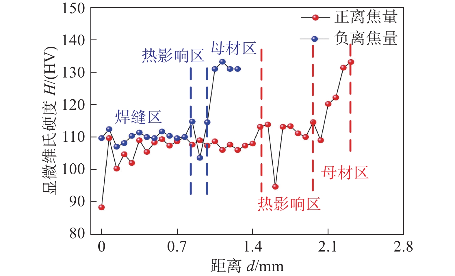
如图10所示,对激光功率为3250 W,焊接速度为10 mm/s,保护气体流量为15 L/min,离焦量为−2 mm和 +2 mm的接头分别进行显微硬度测量.
![]() 图 10 不同离焦量下的显微硬度对比Figure 10. Microhardness comparison under different defocus amounts
图 10 不同离焦量下的显微硬度对比Figure 10. Microhardness comparison under different defocus amounts测量自焊缝最上端区域开始至母材区域结束. 其中母材区域平均硬度约为130 HV,正离焦量时焊缝区的平均硬度约为110 HV,热影响区的平均硬度约为106 HV;负离焦量时焊缝区的平均硬度约为106 HV,热影响区的平均硬度约为109 HV. 导致焊缝区域硬度降低的原因除前文中所述的强化相改变外,还因为在母材中强化相细小而均匀的分布在α-Al基体中,然而由于焊缝区域存在部分Mg元素烧损,使得强化相S的含量减少并且存在于晶界处的网络低熔点共晶组织中,因此焊缝区域的整体硬度会低于母材. 但由于焊缝中心区域存在着大量的细小等轴晶,存在细晶强化作用,硬度降低趋势得以部分抑制. 有相关研究表明,焊缝中心位置低熔点共晶呈连续网状分布容易导致焊缝金属的硬度降低[14]. 因此在宏观上体现为焊缝区域硬度与母材相比呈现较低的水平. 由于负离焦量时焊缝中的强化相S含量较正离焦量时有所减少,并且晶粒较为粗大,使得离焦量为负时,焊缝的硬度值较低.
2.5 气密性测试
如图11所示,分别采用激光功率为3250 W,焊接速度为10 mm/s,保护气体流量为15 L/min,离焦量为+ 2 mm和−2 mm的工艺参数对2块铝合金板的一侧进行封边焊接,在其另一侧开槽.
![]() 图 11 气密性测试试样制备Figure 11. Preparation of sample for air tightness test. (a) the edge sealing weld with defocusing amount of +2 mm; (b) the slotted sample with defocusing amount of +2 mm; (c) the edge sealing weld with defocusing amount of −2 mm; (d) the slotted sample with defocusing amount of −2 mm
图 11 气密性测试试样制备Figure 11. Preparation of sample for air tightness test. (a) the edge sealing weld with defocusing amount of +2 mm; (b) the slotted sample with defocusing amount of +2 mm; (c) the edge sealing weld with defocusing amount of −2 mm; (d) the slotted sample with defocusing amount of −2 mm采用盛水试验对制备的试样进行气密性测试,以水自重所产生的静压来检验结构有无渗漏现象,气密性测试过程和结果如图12所示. 分别向两个槽中注满水,将封边焊缝这侧放到吸水纸上面,静置一段时间,把试样移开,吸水纸均未湿,表明两个封边试样均无水渗漏,因此激光封边焊接的气密性均良好.
![]() 图 12 气密性测试过程和结果Figure 12. Process and results of air tightness testing. (a) the process of testing with defocusing amount of +2 mm; (b) the result of testing with defocusing amount of +2 mm; (c) the process of testing with defocusing amount of −2 mm; (d) the result of testing with defocusing amount of −2 mm
图 12 气密性测试过程和结果Figure 12. Process and results of air tightness testing. (a) the process of testing with defocusing amount of +2 mm; (b) the result of testing with defocusing amount of +2 mm; (c) the process of testing with defocusing amount of −2 mm; (d) the result of testing with defocusing amount of −2 mm3. 结论
(1) 2A12铝合金激光封边焊接焊缝几何特征的主要影响因素依次为离焦量、焊接速度和激光功率,而保护气体流量为非显著性因素.
(2)在熔合线附近和过渡区域均是胞状树枝晶组织,强化相沿晶界分布;在焊缝中心区域是等轴晶组织,强化相主要呈现颗粒状分布于晶界处,少量分布于晶粒内部. 与正离焦量相比,负离焦量时,焊缝的晶粒尺寸较大.
(3)正、负离焦量时,焊缝的硬度均低于母材;采用负离焦量时,焊缝硬度较低. 主要因为是焊接过程中Mg元素的烧损降低了焊缝中强化相S的含量. 离焦量为 +2 mm和−2 mm时,激光封边焊接的气密性均良好.
-
![]()
图 3 模型的残差分布
Figure 3. Residual distribution of the model. (a) the residuals of Penetration; (b) the residuals of weld width
![]()
图 4 实际值与预测值的对比
Figure 4. Comparison of actual and predicted values. (a) the comparison of penetration; (b) the comparison of weld width
![]()
图 5 不同离焦量下激光功率和焊接速度对熔深的影响
Figure 5. Influence of laser power and welding speed on penetration value under different defocusing amounts. (a) −2 mm; (b) 0 mm; (c) +2 mm
![]()
图 6 不同离焦量下激光功率和焊接速度对熔宽的影响
Figure 6. Influence of laser power and welding speed on weld width value under different defocusing amounts. (a) −2 mm; (b) 0 mm; (c) +2 mm
![]()
图 7 不同离焦量下的金相图片
Figure 7. Metallographic pictures under different defocusing amounts. (a) defocusing amount of +2 mm near the fusion line; (b) defocusing amount of −2 mm near the fusion line; (c) defocusing amount of +2 mm at the center of weld; (d) defocusing amount of −2 mm at the center of weld
![]()
图 8 不同离焦量下的微观组织
Figure 8. Microstructure under different defocusing amounts. (a) defocusing amount of +2 mm near the fusion line; (b) defocusing amount of −2 mm near the fusion line; (c) defocusing amount of +2 mm at the transition region; (d) defocusing amount of −2 mm at the transition region; (e) defocusing amount of +2 mm at the center of weld; (f) defocusing amount of −2 mm at the center of weld
![]()
图 9 不同离焦量下接头中Mg元素的含量和Cu/Mg
Figure 9. The content of Mg element and Cu/Mg in joint under different defocusing amounts. (a) the content of Mg element; (b) Cu/Mg
![]()
图 10 不同离焦量下的显微硬度对比
Figure 10. Microhardness comparison under different defocus amounts
![]()
图 11 气密性测试试样制备
Figure 11. Preparation of sample for air tightness test. (a) the edge sealing weld with defocusing amount of +2 mm; (b) the slotted sample with defocusing amount of +2 mm; (c) the edge sealing weld with defocusing amount of −2 mm; (d) the slotted sample with defocusing amount of −2 mm
![]()
图 12 气密性测试过程和结果
Figure 12. Process and results of air tightness testing. (a) the process of testing with defocusing amount of +2 mm; (b) the result of testing with defocusing amount of +2 mm; (c) the process of testing with defocusing amount of −2 mm; (d) the result of testing with defocusing amount of −2 mm
表 1 2A12铝合金的化学成分(质量分数,%)
Table 1 Chemical compositions of the 2A12 aluminum alloy
Cu Mg Mn Fe Si Zn Ti Ni Al 4.12 1.47 0.65 0.31 0.23 0.15 0.03 0.01 余量  下载: 导出CSV
表 2 因素编码及水平表
Table 2 Factor coding and level table
水平 激光功率 P/W 焊接速度 v/( mm·s−1) 离焦量 df /mm 保护气体流量 Q/(L·min−1) −1 2 750 8 −2 10 0 3 000 10 0 15 1 3 250 12 +2 20
下载: 导出CSV
表 3 响应曲面的设计与结果
Table 3 Design and results of response surface
序号 激光功率P/W 焊接速度 v/(mm·s−1) 离焦量 df/mm 保护气体流量Q/(L·min−1) 熔深H/μm 熔宽B/μm 1 2 750 8 0 15 1 330.249 3 944.42 2 3 250 8 0 15 1 552.286 4 064.147 3 2 750 12 0 15 1 012.336 3 049.104 4 3 250 12 0 15 1 095.403 3 533.258 5 3 000 10 −2 10 1 216.942 3 997.757 6 3 000 10 2 10 919.334 2 905.551 7 3 000 10 −2 20 1 766.443 4 095.258 8 3 000 10 2 20 893.464 2 932.171 9 2 750 10 0 10 835.062 2 791.057 10 3 250 10 0 10 1 377.999 3 846.654 11 2 750 10 0 20 1 111.183 3 670.094 12 3 250 10 0 20 1 150.340 3 526.237 13 3 000 8 −2 15 1 572.066 4 042.613 14 3 000 12 −2 15 1 488.453 4 014.622 15 3 000 8 2 15 953.094 3 568.991 16 3 000 12 2 15 865.469 3 065.678 17 2 750 10 −2 15 1 365.455 3 995.184 18 3 250 10 −2 15 1 719.999 4 021.145 19 2 750 10 2 15 958.764 2 750.043 20 3 250 10 2 15 985.532 2 983.055 21 3 000 8 0 10 1 125.832 3 622.271 22 3000 12 0 10 932.438 2 845.015 23 3 000 8 0 20 1 300.346 3 799.699 24 3 000 12 0 20 819.857 2 624.423 25 3 000 10 0 15 1 251.297 3 866.230 26 3 000 10 0 15 1 467.777 4 007.034 27 3 000 10 0 15 1 309.242 3 960.410 28 3 000 10 0 15 1 335.353 2 970.695 29 3 000 10 0 15 1 746.134 4 034.367
下载: 导出CSV
表 4 熔深的响应曲面诊断结果
Table 4 Penetration value of response surface diagnostic results
方差来源 平方和U 自由度f 均方u 检验值F 显著性P 模型 1.948 × 10⁶ 14 1.392 × 10⁵ 11.67 < 0.000 1 激光功率 1.583 × 10⁵ 1 1.583 × 10⁵ 13.28 0.002 7 焊接速度 2.187 × 10⁵ 1 2.187 × 10⁵ 18.35 0.000 8 离焦量 1.052 × 10⁶ 1 1.052 × 10⁶ 88.29 < 0.000 1 保护气体流量 22 917.94 1 22 917.94 1.92 0.187 2 残差 1.669 × 10⁵ 14 11 919.18 失拟项 1.483 × 10⁵ 10 14 833.90 3.20 0.136 6 纯差 18 529.50 4 4 632.37 R2 0.921 1 R2Adj 0.842 2
下载: 导出CSV
表 5 熔宽的响应曲面诊断结果
Table 5 weld width value of response surface diagnostic results
方差来源 平方和U 自由度f 均方u 检验值F 显著性P 模型 6.539 × 10⁶ 14 4.671 × 10⁵ 10.75 < 0.000 1 激光功率 2.337 × 10⁵ 1 2.337 × 10⁵ 5.38 0.036 0 焊接速度 1.453 × 10⁶ 1 1.453 × 10⁶ 33.45 < 0.000 1 离焦量 3.128 × 10⁶ 1 3.128 × 10⁶ 72.01 < 0.000 1 保护气体流量 34 088.33 1 34 088.33 0.78 0.390 7 残差 6.174 × 10⁵ 14 44 096.50 失拟项 5.658 × 10⁵ 10 56 584.04 5.34 0.060 4 纯差 42 412.75 4 10 603.19 R2 0.914 9 R2Adj 0.829 8
下载: 导出CSV
表 6 点扫结果(质量分数,%)
Table 6 The result of dot scanning
区域 Al Mg Cu A 82.47 1.95 15.58 B 95.71 1.12 5.41
下载: 导出CSV
-
[1] He S, Liu L Y, Zhao Y Q, et al. Comparative investigation between fiber laser and disk laser: Microstructure feature of 2219 aluminum alloy welded joint using different laser power and welding speed[J]. Optics & Laser Technology, 2021, 141: 107121.
[2] Hou J C, Li R F, Xu C, et al. A comparative study on microstructure and properties of pulsed laser welding and continuous laser welding of Al-25Si-4Cu-Mg high silicon aluminum alloy[J]. Journal of Manufacturing Processes, 2021, 68: 657 − 667. doi: 10.1016/j.jmapro.2021.05.064
[3] Zhang R Z, Buchanan C, Matilainen V, et al. Mechanical properties and microstructure of additively manufactured stainless steel with laser welded joints[J]. Materials & Design, 2021, 208: 109921.
[4] Rinne J, Seffer O, Nothdurft S, et al. Investigations on the weld metal composition and associated weld metal cracking in laser beam welded steel copper dissimilar joints[J]. Journal of Materials Processing Technology, 2021, 296: 117178. doi: 10.1016/j.jmatprotec.2021.117178
[5] Liu Y Q, Fan J Z, Hao X X, et al. Advanced hermetic electronic packaging based on lightweight silicon/aluminum composite produced by powder metallurgy technique[J]. Rare Metals, 2016(6): 1 − 7.
[6] 周明智, 雷党刚, 李 正. 高硅铝合金壳体激光封焊缺陷及机制分析[J]. 电子机械工程, 2013, 6(6): 58 − 60,68. doi: 10.19659/j.issn.1008-5300.2013.06.013 Zhou Mingzhi, Lei Danggang, Li Zheng. Analysis on defects and mechanism of laser sealing welding of high silicon aluminum alloy shell[J]. Electro-Mechanical Engineering, 2013, 6(6): 58 − 60,68. doi: 10.19659/j.issn.1008-5300.2013.06.013
[7] 王成, 孙乎浩, 陈 澄. 铝合金壳体激光封焊工艺参数对其气密性影响[J]. 电子工艺技术, 2016, 37(6): 342 − 344. doi: 10.14176/j.issn.1001-3474.2016.06.010 Wang Cheng, Sun Huhao, Chen Cheng. Effect of laser sealing welding parameters on air tightness of aluminum alloy shell[J]. Electronic Process Technology, 2016, 37(6): 342 − 344. doi: 10.14176/j.issn.1001-3474.2016.06.010
[8] 聂要要, 邝小乐, 王亚松, 等. 微波模块铝合金壳体激光封焊工艺参数对焊缝质量影响的研究[J]. 雷达与对抗, 2018, 38(4): 34 − 37. doi: 10.19341/j.cnki.issn.1009-0401.2018.04.008 Nie Yaoyao, Kuang Xiaole, Wang Yasong, et al. Study on the effect of laser sealing welding parameters on weld quality of microwave module aluminum alloy shell[J]. Radar and Countermeasures, 2018, 38(4): 34 − 37. doi: 10.19341/j.cnki.issn.1009-0401.2018.04.008
[9] Jiang J, Zhang Y, Wang Y, et al. Microstructure and mechanical properties of thixoforged complex box-type component of 2A12 aluminum alloy[J]. Materials & Design, 2020, 193: 108859.
[10] 方远方, 张 华, 窦程亮. 2A12-T4/7A09-T6铝合金搅拌摩擦焊搭接接头性能分析[J]. 焊接学报, 2020, 41(1): 92 − 96,107-108. Fang Yuanfang, Zhang Hua, Dou Chengliang, et al. Performance analysis of lap joints of 2A12-T4/7A09-T6 aluminum alloy by friction stir welding[J]. Transactions of the China Welding Institution, 2020, 41(1): 92 − 96,107-108.
[11] Yan J, Zeng X Y, Gao M, et al. Effect of welding wires on microstructure and mechanical properties of 2A12 aluminum alloy in CO2 laser-MIG hybrid welding[J]. Applied Surface Science, 2009, 255(16): 7307 − 7313. doi: 10.1016/j.apsusc.2009.03.088
[12] 余江瑞. 2A12铝合金薄板熔焊对接接头大变形及失效力学行为研究[D]. 兰州: 兰州理工大学, 2011. Yu Jiangrui. Large deformation and failure mechanical behavior of fusion welding butt joint of 2A12 aluminum alloy sheet[D]. Lanzhou: Lanzhou University of Technology, 2011.
[13] 戴起勋. 金属材料学[M]. 北京: 化学工业出版社, 2018. Dai Qixun. Metal material science[M]. Beijing: Chemical Industry Press, 2018.
[14] 顾 华. 2A12厚板铝合金电子束焊接接头组织及工艺研究[D]. 哈尔滨: 哈尔滨工业大学, 2017. Gu Hua. Study on microstructure and process of 2A12 thick aluminum alloy electron beam welding joint[D]. Harbin: Harbin Institute of Technology, 2017.
-
期刊类型引用(5)
1. 袁明新,戴现令,刘超,孙宏伟,王磊. 基于空间位置和轮廓线距离的船舶焊缝特征参数提取. 焊接学报. 2023(01): 84-92+133-134 .  本站查看
本站查看
2. 陈兵,贺晟,刘坚,陈圣峰,路恩会. 基于轻量化DeepLab v3+网络的焊缝结构光图像分割. 中国激光. 2023(08): 49-58 . 百度学术
3. 张开放,刘蔓,陈欢群,柴绪彬. 基于电容式传感器的焊缝特征检测技术. 自动化与仪表. 2023(06): 81-84+90 . 百度学术
4. 祖海英,卢兴宇,宋玉杰,李大奇. 基于激光熔覆再制造PDC钻头的机器人仿真分析. 焊接学报. 2022(10): 71-76+117-118 . 本站查看
5. 夏卫生,方向瑶,杨帅,林富明,杨云珍. 基于频率调谐的焊缝红外图像显著性检测算法. 焊接. 2021(04): 8-12+62 . 百度学术
其他类型引用(9)


计量
- 文章访问数: 434
- HTML全文浏览量: 39
- PDF下载量: 124
- 被引次数: 14
