Effect of driving force on molten pool behavior of 2219 aluminum alloy DLBSW process
-
摘要: 为了探索激光焊接熔池驱动力与焊接过程中熔池流动之间的关系,构建2219铝合金T形结构双激光束双侧同步焊接(dual laser-beam bilateral synchronous welding,DLBSW)过程热-流耦合模型. 分析表面张力、反冲压力、重力及热浮力对熔池流动的驱动作用,并阐述这些驱动力共同作用下的熔池流动机理. 结果表明,熔池表面的流体,其主要受到表面张力的驱动作用;对于熔池下端左侧及后方形成的环流,其主要受到表面张力、热浮力及重力的共同驱动作用;匙孔下方熔池底部在重力及热浮力的共同作用下沿熔池边缘流动.
-
关键词:
- 双激光束双侧同步焊接 /
- 表面张力 /
- 反冲压力 /
- 重力 /
- 热浮力
Abstract: The thermal-fluid coupling model of 2219 aluminum alloy T-type structure with dual laser-beam bilateral synchronous welding (DLBSW) was established to explore the relationship between the driving force of molten pool and flow field during DLBSW process. The driving effects of surface tension, recoil pressure, gravity and thermal buoyancy on molten pool flow field were analyzed, and the mechanism of molten pool flow field under combined influence of driving forces was indicated. The results show that: the flow fluid on the surface of molten pool is mainly driven by surface tension; the circulation formed at the left and back of the bottom of the molten pool are mainly co-driven by surface, gravity and thermal buoyancy; the bottom of molten pool below keyhole flows along the edge of molten pool under co-driven of gravity and thermal buoyancy. -
0. 序言
异种铝合金的焊接可以适应更多样化的工况需求,一直受到研究界的广泛关注[1-3].由于物性参数上存在差异,在焊接时更容易产生气孔、熔合不均匀等问题,导致接头严重变形或软化,使接头性能受限. 近年来,激光振镜焊接发展为一个活跃的研究领域,通过光束振荡可以有效抑制焊接缺陷,如减少气孔[4-6],降低宏观偏析[7],细化焊缝晶粒[8],抑制焊接裂纹[9-10]等. 虽然激光振镜焊接技术具有显著的优势,但存在功率损失率高,灵活性差的问题.
研究表明,功率调制激光焊接的能量利用率更高,通过改变能量作用的方式对焊接缺陷的抑制和性能改善更有利. Zhang 等人[11]研究发现功率调制对AZ31合金激光焊接质量的影响高度依赖于激光功率密度,在低功率密度范围内,采用适当的功率调制可以显著提高焊接过程的激光能量耦合效率,有效降低能量损失,其原因是形成了深匙孔并能维持数微秒[12],这一点对于改善铝等高反射率材料的激光焊接工艺热效率意义重大. 此外功率调制可以更灵活地调控匙孔行为,对激光功率进行正弦调制可以实现当激光功率处于峰值期时匙孔加深,激光功率处于低谷期时匙孔缩短[13],对于匙孔型气孔的抑制尤为关键;Zhang 等人[14]的研究证明功率调制可以有效减少甚至消除镁合金焊缝表面的凹陷,进而提高了接头强度. 由于焊接过程变量数量的增加,功率调制技术为控制能量沉积提供了多种可能性,使得焊接过程行为以及焊接接头的最终性能可以得到有利的改变.
研究开发了全域功率调制激光振镜焊接系统,该系统突出的优势为扫描轨迹内36个点的功率可以单独设置,从而实现了激光功率随实际扫描位置而变的特性. 文中采用三种不同的焊接模式对6061-T6与5052-H112铝合金进行焊接,分别是激光焊接模式(LW)、定功率(CP)激光振镜焊接和梯度功率(GP)激光振镜焊接模式. 分析了三种模式对异种铝合金接头焊缝成形、显微组织和力学性能的影响,解释了微观组织变化的机制. 为异种铝合金焊接质量提升提供了新的见解和技术指导.
1. 试验方法
采用尺寸为150 mm × 80 mm × 2 mm的AA6061-T6铝合金和150 mm × 80 mm × 2.2 mm的5052-H112铝合金进行对接焊试验,母材的化学成分如表1所示. 6系铝合金是以Mg和Si为主要元素的中等强度铝合金,强化相以Mg2Si为主,5系铝合金为Al-Mg合金,镁主要以Mg2Al3的强化相存在. 采用PSI振镜头和MFSC
6000 W光纤激光器进行焊接,光纤芯径为0.4 mm,激光波长为1 064 nm,扫描轨迹为圆形. 激光振镜焊接示意图及CP/GP模式下激光功率分布如图1所示,其中x方向为焊接方向,y方向为垂直焊缝方向. 焊接时通入纯度为99.999%的氩气(流量为20 L/min)作为保护气体. 焊接前用丙酮擦拭铝板,再用细砂纸抛光去除油渍和氧化膜. 焊接试验过程中将激光头向焊接方向倾斜10 °(在x-z平面内),以避免光的反射损坏光学元件,详细优化后焊接试验参数见表2.表 1 铝合金的化学成分(质量分数,%)Table 1. Chemical composition of aluminium alloys材料 Mg Fe Mn Si Cr Ti Cu Zn Al 6061 0.84 0.50 0.09 0.52 0.22 0.13 0.18 0.16 余量 5052 2.22 0.19 0.07 0.09 0.20 — 0.08 0.01 余量 表 2 优化后的焊接试验参数Table 2. Optimised experimental welding parameters焊接参数 取值 LW CP GP 功率P/kW 4.42 4.42 $\left\{ \begin{array}{l}P=P_{\rm{t} }\times 0.95\left(1-0.45{y}/A\right),y\geqslant 0\\ P=P_{\rm{t} }\times 0.95\left(1 + 0.45{y}/A\right),y < 0\end{array}\right.$ 焊接速度vw/(m·min−1) 0.6 扫描频率f/Hz 100 扫描幅度A/mm 0.4 注:Pt = 6 kW,x,y为激光光斑的坐标位置 焊接后用相机记录所有焊缝的表面形貌,并使用标准金相制备技术切割和抛光截面样品. 样品分别用240 ~
2000 目的碳化硅(SiC)砂纸研磨,再用3 μm,2.5 μm和0.25 μm金刚石悬浮液进行抛光,并用水和酒精彻底清洗,蚀刻在含有2 mL HF,6 mL HNO3和92 mL DI的溶液中进行. 采用蔡司M2M光学显微镜观察焊缝横截面形貌. 用电子背散射衍射仪(EBSD,步长2 µm)检测了焊接接头的微观结构. 采用工业计算机断层扫描(CT sanyingts20131)检验接头内部的气孔.2. 结果与讨论
2.1 焊缝形貌及显微组织
不同焊接模式下焊缝表面形貌如图2所示,由图可知,激光焊焊缝正面成形较差,表面覆盖大量飞溅形成的小颗粒,焊缝宽度变化大,背面熔宽波动更显著,表明焊接过程中大量的热量快速积聚导致焊缝不断凹陷造成过度熔合,通常焊接一小段距离时就会发生背面焊穿现象. 而激光振镜焊接过程(CP/GP)的焊缝表面平整,成形得到改善,飞溅明显减少. 所不同的是CP模式焊缝背面熔合不良,表明焊接过程能量有所分散. 而GP模式焊缝背面熔合程度最好. 这与三种模式的能量分布有关,后面详细讨论.
为检测焊缝内部的气孔率和熔合情况,对焊缝表面进行CT测试,结果如图3所示. 图中显示激光焊焊缝内部存在较多分散的大尺寸气孔(图3(a)),焊缝完全熔透. 对于CP模式焊缝(图3(b))内部未见明显气孔,但熔合线上密集的链状孔洞表示焊缝熔透程度差,并未实现冶金结合. 对于GP模式(图3(c)),焊缝内部没有分散的气孔,熔合线上仍存在链状孔洞,但是相比CP模式,焊缝熔透程度显著改善. 经过反复的参数优化,最终实现了焊接接头的完全熔透,下面对优化后的接头组织与性能进行着重分析.
典型的焊接接头截面几何特征的宏观形貌如图4所示. 对于传统的激光焊(图4(a)),焊缝熔合线上窄下宽,焊缝中心凹陷明显,说明接头经历了严重的热量冲击,接头熔合区域最窄,原因是激光光斑直径小,热源能量高度集中,光源的作用面积最小,截面存在分散的气孔;对于激光振镜焊接模式,热源作用面积明显增大(图4(b)和图4(c)). CP模式焊缝熔合线上宽下窄,焊缝中心少量凹陷(图4(b)),GP模式焊缝熔合线上下宽度接近,焊缝中心几乎无凹陷(图4(c)),表明由母材区到焊缝区截面平滑过渡,成形均匀性更好,接头变形最小,预测GP模式铝合金接头在进行拉伸测试时失效的过程相对缓慢,即表现为较高的抗拉强度.
用扫描电镜观察样品横截面的显微组织,如图5所示,激光焊模式下(图5(a))焊缝熔合区(FZ)组织显示为大尺寸( ~ 53 µm)和长晶界的枝晶,而CP模式下(图5(b))焊缝熔合区组织为破碎和断裂的均匀等轴晶,尺寸约为 ~ 24 µm,表明焊接过程中光束的快速转动对熔池产生了强烈的搅拌作用,进而改变了熔池的凝固模式,使得大尺寸的晶粒细化为小尺寸晶粒;GP模式下(图5(c))焊缝熔合区组织为等轴晶,尺寸为 ~ 26 µm,相比CP模式尺寸略有增大.热影响区(HAZ)的组织变化有类似的趋势,从功率模式对两种合金组织演化的影响来看,6061侧组织的晶粒尺寸和晶粒形貌对功率变化的敏感性明显高于5052侧组织,体现在6061/HAZ侧的晶粒尺寸随功率模式的变化比5052/HAZ侧更为显著.
采用EBSD定量表征了不同焊接方式下焊缝的晶粒尺寸和形貌变化. 图6为不同模式下焊接接头的晶粒组织对比. 焊缝组织由熔合区的等轴晶和热影响区的柱状晶组成. 经过统计得出,激光焊(LW)、CP和GP模式焊缝中晶粒直径小于100 µm的等轴晶所占比例分别为31%,69%和77%. 图7为焊缝熔合区等轴晶和热影响区枝晶的晶粒尺寸统计,分析得出LW/CP/GP模式平均等轴晶粒尺寸分别为63 µm,54 µm和58 µm. 结果表明,激光振镜模式(CP和GP)下等轴晶的比例比激光焊(LW)模式有所增加. 相比之下,GP模式焊缝中等轴晶所占比例更高,表示焊缝熔合区晶粒的等轴化程度更高,但平均等轴晶粒尺寸略大于CP模式焊缝,与图5中焊缝熔合区组织一致. 另外LW/CP/GP模式对应的热影响区平均晶粒尺寸分别为99 µm,77 µm和80 µm,说明热影响区柱状晶粒的大小也有类似的变化趋势. 图中可以看出,热影响区晶粒在振荡模式下趋向于向等轴晶转变,这无疑将提高焊缝中等轴晶的比例.
2.2 拉伸性能测试
不同焊接模式下接头的拉伸强度测试结果如图8所示,所有焊缝都在熔合区的位置失效,每组工艺下取5个试样以确定接头的平均强度. 图中显示,LW/CP/GP模式接头的抗拉强度分别为155.3 MPa,158.5 MPa和180.8 MPa. 结果显示,激光振镜焊接试样(CP/GP)的平均抗拉强度高于激光焊接试样(LW),表明光束振荡降低了接头的软化程度,其中GP模式接头强度最高,一方面是焊缝内产生了更多的等轴晶,另一方面是焊缝形貌的改善. 接头强度测试结果与2.1部分的预测结果一致.
试样拉伸试验后的断面形貌如图9所示. 激光焊的焊缝断面有粗大的韧窝,同时发现有明显的气孔存在(图9(a)),而CP模式焊缝断面也有少量的气孔,但韧窝相对密集,断裂面有明显的撕裂痕迹,很明显,激光振镜焊接使得焊缝中的气孔减少,其原因是扫描区域的重叠对焊缝熔合区有重复加热效应[15]. GP模式焊缝断面为更细密的韧窝,表明接头具有最好的断裂韧性.
2.3 显微硬度
试样焊缝横截面上的显微硬度测试结果如图10所示. 激光焊接试样熔合区的平均显微硬度为53 HV. 而CP和GP模式分别为65 HV和77 HV. 激光振镜焊接接头熔合区的平均显微硬度大于激光焊接头,可以通过2.1节中讨论的焊缝晶粒细化说明,遵循理论上的Hall-Petch效应[16]. 等轴晶的尺寸越小,意味着焊缝组织中晶界所占的比例越高. 而晶界对位错的移动有阻碍作用,GP模式焊缝中等轴晶的数量最多,等轴化程度也最高,因此具有最高的显微硬度. 在焊接过程中,热循环促进了热影响区的晶粒粗化和过时效,因此该区域的显微硬度低于基材,显微硬度测定结果与显微组织观察结果吻合较好.
2.4 焊缝形成机制
激光振镜焊接过程中光束沿着螺旋线的轨迹扫描实施焊接,其轨迹方程表示为[17]
$$\left\{ \begin{gathered} x(t) = {x_{{0}}} + {v_{\rm{w}}}t + A\sin (2\text{π} ft + {\varphi _x}) \\ y(t) = {y_{{0}}} + A\sin (2\text{π} ft + {\varphi _y}) \\ \end{gathered}\right. $$ (1) 式中:x(t)和y(t)为光斑在x和y方向上的实际位置;x0和y0分别表示起点位置的x和y坐标;t是焊接时间;(φx,φy)是焦点的初始相位.
综合前期学者的研究得出优化后的激光振镜焊接过程中光束能量分布模型为[18-19]
$$ I = \frac{{\eta Pv(t)}}{{2\text{π} \alpha {r_0}}}e^\tfrac{{ - v(t) \cdot ({{(x - x(t))}^2} + {{(y - y(t))}^2})}}{{2\alpha {r_0}}} $$ (2) 式中:η为材料的激光吸收率;v(t)为光束扫描速度;a为热扩散系数;P为激光功率;r0为光斑直径.
激光照射在母材上的能量为
$$ E(x, y)=\int_{0}^{T} I(x, y, t) {\rm{d}} t $$ (3) 式中:I(x, y, t)为光束在位置(x, y)和时间t处的能量. 主要参数的取值为r0 = 0.4 mm,α=3.2 × 10⁻⁶ m2/s,x0 = y0 = 0,φx−φy = π/2,η = 0.8. 将表2中对应的参数和功率表达式代入式(1)和式(2),通过式(3)积分,得到不同模式的能量分布.
图11显示了根据式(1) ~ 式(3)得到的三种模式在5个振荡周期内焊缝表面及侧面能量沉积情况. 图中显示,在无振荡的情况下,激光束的直线运动使激光能量集中在焊缝中心(图11(a),11(b)),能量密度峰值为482.9 J/mm2. 对于振镜焊模式,由于在扫描轨迹的不同位置光束有不同的重叠密度,能量最终沿焊缝边缘沉积. GP模式有3个能量峰,而CP模式有2个能量峰,GP模式的能量密度峰值(332.4 J/mm2)低于CP模式(429.2 J/mm2),都低于激光焊能量密度峰值. 此外GP模式下焊缝中心线处的能量密度(184.6 J/mm2)明显高于CP模式(143.1 J/mm2),因此保证了焊缝中心的良好熔合,并提升了热源利用率.
2.5 微观组织形成机制
根据结晶理论,熔池的结晶形态完全取决于结晶过程中固液界面前方成分过冷的程度. 成分过冷区宽度计算式为[20-21]
$$ \Delta x=\frac{2 D_{{\rm{L}}}}{R}-\frac{2 k_{0} G D_{{\rm{L}}}^{2}}{m_{{\rm{L}}} C_{0}\left(1-k_{0}\right) R^{2}} $$ (4) 式中:R为熔池结晶速率;G为液相温度梯度;DL为液相溶质原子扩散系数;mL为液相斜率;C0为合金的原始成分浓度;k0为平衡分布系数. 激光焊接时,焊缝中心容易形成等轴晶组织,等轴晶的数量取决于G和R的值. G值越大,∆x越小. 熔池结晶速率表示为
$$ \mathit{R} \mathrm= {\nu } _{\rm{w}}\mathrm{cos\alpha } $$ (5) 式中:${\nu } _{\rm{w}}$为焊接速度;α为结晶等温面法向与焊接方向之间的夹角. 在中心线处,α = 0,因此R ≈ ${\nu } _{\rm{w}} $,∆x随G的减小而增大. 根据之前的研究[5],由于GP模式对焊缝的重熔效果更强,熔池具有最小的温度梯度,因此相同扫描频率下成分过冷区宽度最大. 但由于GP模式下焊缝中心线存在能量峰值,导致晶粒略微长大,平均晶粒尺寸比CP模式下大.
$$ I=I_0 \exp \left[-\frac{16 \text{π} \gamma^3 T_0^2}{3 \Delta h_{\rm{m}}^2 k_{\rm{B}} T} \cdot \frac{1}{\left(\Delta T_C\right)^2}\right] $$ (6) 式中:I0为指数因子; γ为界面能;∆hm为单位体积焓;kB为玻尔兹曼常数;∆TC为晶体生长的过冷度. 由上式可知,温度梯度越小,∆TC越大,异质形核率I越高,因此GP模式下的焊缝异质形核率最高,LW模式下最小. 关于光束振荡对微观组织的影响,Gao等人[22]指出,在相同振幅下,镁合金的扫描频率与晶粒尺寸成反比,分析认为这是由于光束搅拌使断裂枝晶的形核位置增加所致,其原因是振镜过程高速转动的激光束会产生强对流,使熔池内的流量有增大的趋势,这种增强的流体流动可能会破坏次生枝晶臂,为等轴晶粒的形成提供更多的潜在核. 综上,在激光振镜焊接过程中,通过调节激光功率为梯度渐变的分布模式,可以降低熔池的温度梯度,进而形成更大面积的等轴晶粒.
3. 结论
(1) 激光功率模式对焊缝成形影响较大,振镜激光改善了传统激光焊由于热积累严重导致的焊缝表面凹陷问题,GP模式下焊缝凹陷程度最小,背面熔合程度最好. 激光焊焊缝内部存在大尺寸气孔,振镜模式焊缝未见明显气孔.
(2) 振镜模式(CP和GP)下焊缝熔合区等轴晶的比例比激光焊(LW)模式有所增加,其中GP模式等轴晶比例最高为77%,原因是GP模式的熔池温度梯度最小,产生最大的过冷度和异质形核率,更有利于获得等轴晶.
(3) 晶粒尺寸的变化与材料表面的能量分布密切相关. 对于振荡激光束,能量主要沿焊缝边缘沉积,能量密度的峰值小于无振荡激光模式,GP模式下焊缝中心的能量密度高于CP模式,因此保证了焊缝中心的良好熔合,并提升了热源利用率.
(4) 振荡试样的平均抗拉强度高于无光束振荡试样,这是焊缝形貌优化和晶粒尺寸细化的结果.焊缝熔合区的平均显微硬度大于激光焊接头. GP模式焊缝具有最少的焊接缺陷和最高的强度,焊缝断面显示更细密的韧窝,熔合区显微硬度最高.
-
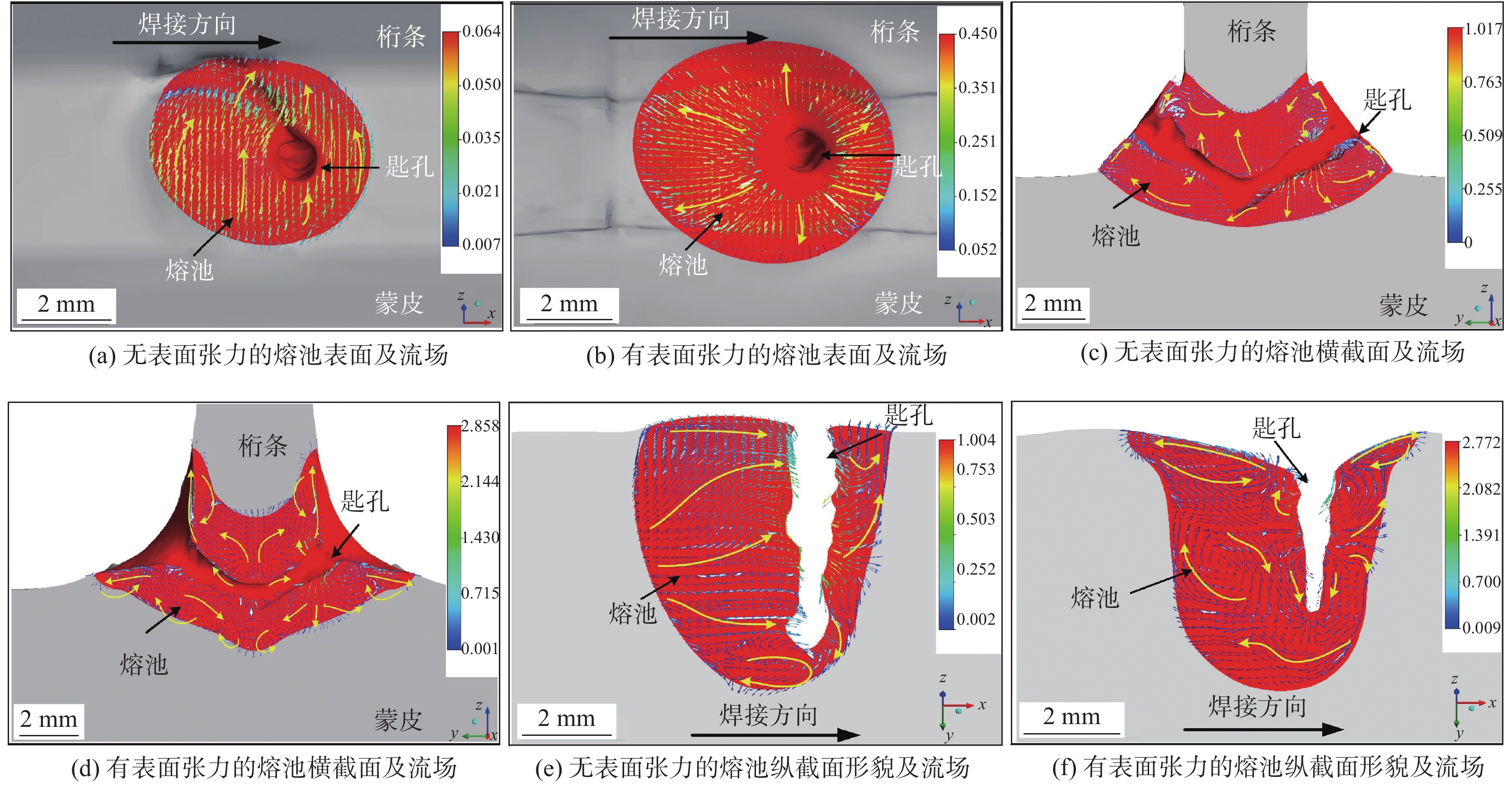
图 5 表面张力对熔池形貌及流场的影响
Figure 5. Effect of surface tension on molten pool morphology and flow field. (a) morphology and flow field of molten pool surface without surface tension; (b) morphology and flow field of molten pool surface with surface tension; (c) morphology and flow field of cross section without surface tension; (d) morphology and flow field of cross section with surface tension; (e) morphology and flow field oflongitudinal section without surface tension; (f) morphology and flow field oflongitudinal section with surface tension
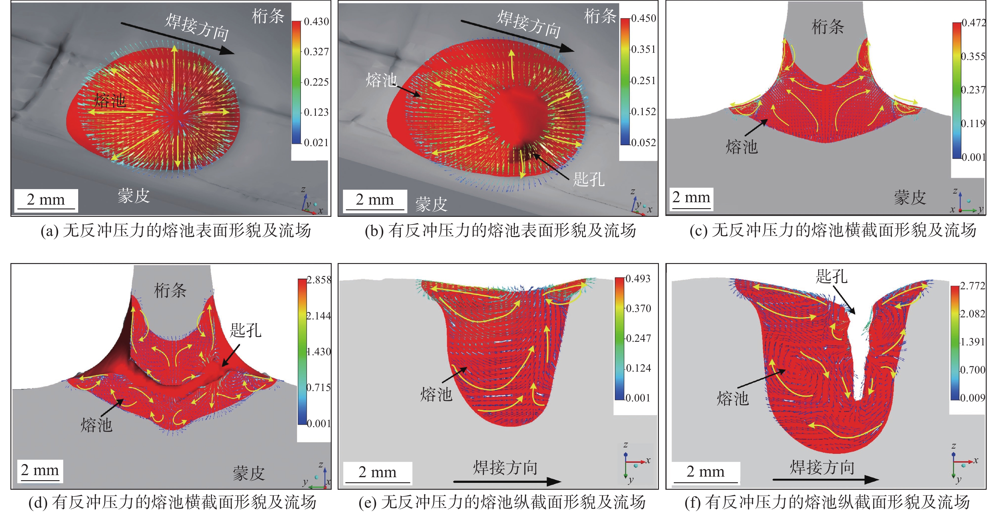
图 7 反冲压力对熔池形貌及流场的影响
Figure 7. Effect of recoil pressure on molten pool morphology and flow field. (a) (c) (e) morphology and flow field of molten pool surface, cross section and longitudinal section without recoil pressure; (b) (d) (f) morphology and flow field of molten pool surface, cross section and longitudinal section with recoil pressure
图 8 反冲压力对熔池形貌及匙孔壁区域流场的作用机理
Figure 8. Formation mechanism of recoil pressure on molten pool morphology and keyhole wall flow field. (a) comparison of cross sectional morphology of molten pool; (b) fluid flow in keyhole wall region; (c) comparison of longitudinal sectional morphology of molten pool; (d) fluid flow in keyhole wall region
-
[1] 王惠芬, 杨碧琦, 刘刚. 航天器结构材料的应用现状与未来展望[J]. 材料导报, 2018, 32(S1): 395 − 399. Wang Huifen, Yang Biqi, Liu Gang, et al. Application status and future prospect of materials for spacecraft structures[J]. Materials Reports, 2018, 32(S1): 395 − 399.
[2] 陈聪. 高强铝合金光纤激光切焊一体化关键技术与机理研究[D]. 武汉: 华中科技大学, 2017. Chen Cong. Fiber laser cutting-welding integrative technique of high strength aluminum alloy[D]. Huazhong University of Science and Technology, 2017.
[3] 占小红, 欧文敏, 魏艳红, 等. 飞机壁板先进焊接技术应用现状[J]. 航空制造技术, 2013(22): 42 − 44. Zhan Xiaohong, Ou Wenmin, Wei Yanhong, et al. Application status of advanced welding technology of aircraft panels[J]. Aeronautical Manufacturing Technology, 2013(22): 42 − 44.
[4] Rendigs K H. Aluminium structures used in aerospace-status and prospects[J]. Materials Science Forum, 1997, 242: 11 − 24. doi: 10.4028/www.scientific.net/MSF.242.11
[5] Dittrich D, Standfuss J, Liebscher J, et al. Laser beam welding of hard to weld Al alloys for a regional aircraft fuselage design-first results[J]. Physics Procedia, 2011, 12: 113 − 122. doi: 10.1016/j.phpro.2011.03.015
[6] Wang H, Shi Y, Gong S. Numerical simulation of laser keyhole welding processes based on control volume methods[J]. Journal of Physics D-Applied Physics, 2006, 39(21): 4722 − 4730. doi: 10.1088/0022-3727/39/21/032
[7] Lange F, Artinov A, Bachmann M, et al. Numerical simulation of the weld pool dynamics during pulsed laser welding using adapted heat source models[J]. Procedia CIRP, 2018, 74: 679 − 682. doi: 10.1016/j.procir.2018.08.044
[8] Zhang R, Tang X, Xu L, et al. Study of molten pool dynamics and porosity formation mechanism in full penetration fiber laser welding of Al-alloy[J]. International Journal of Heat and Mass Transfer, 2020, 148: 119089. doi: 10.1016/j.ijheatmasstransfer.2019.119089
[9] Zhan X, Chen J, Wei Y, et al. Heat source analyses of dual laser-beam bilateral synchronous welding for T-joint[J]. China Welding, 2011, 20(1): 28 − 33.
[10] Li L, Peng G, Wang J, et al. Numerical and experimental study on keyhole and melt flow dynamics during laser welding of aluminium alloys under subatmospheric pressures[J]. International Journal of Heat and Mass Transfer, 2019, 133: 812 − 826. doi: 10.1016/j.ijheatmasstransfer.2018.12.165
[11] 张聃. Invar合金激光-MIG复合焊接过程多相耦合流场行为研究[D]. 南京: 南京航空航天大学, 2018. Zhang Dan. Study on multiphase coupled flow field behavior during laser-mig hybrid welding of invar alloy[D]. Nanjing: Nanjing University of Aeronautics and Astronautics, 2018.
-
期刊类型引用(3)
1. 廖巍,郭彦兵,张旺,曹培,邓先钦,季怡萍. 激光焊接304不锈钢气体柜应力腐蚀失效分析. 热加工工艺. 2022(07): 148-153 .  百度学术
百度学术
2. 谭润泽,李晓彬,乐京霞. 基于结构应力法的薄板对接焊缝疲劳性能. 华中科技大学学报(自然科学版). 2020(10): 81-85 .  百度学术
百度学术
3. 向章,王佳,何庆中,赵献丹. 焊点间距和直径对波纹板组件疲劳寿命的影响. 铸造技术. 2018(12): 2842-2846+2853 .  百度学术
百度学术
其他类型引用(2)


 下载:
下载:


