
Design and modeling analysis of saddle seam welding robot
-
摘要: 针对目前马鞍形焊缝焊接装备灵活性差,自动化程度低,接头质量稳定性不足等问题,开发了一种新型的管外锚固式四轴焊接机器人. 通过对机器人机构合理简化建立了D-H连杆坐标系,推导了机器人的正逆运动学表达式,并结合机器人关节变量的限位值确定了逆运动学解的唯一性. 通过MATLAB软件对机器人运动学进行了仿真,仿真结果表明,推导的正逆运动学方程模型完全正确. 通过制作样机进行焊接试验,结果表明,焊缝成形致密美观,机器人焊枪末端在x,y,z方向的误差均在±0.35 mm以内,完全满足工程上自动化焊接的需要,为马鞍形焊缝焊接机器人的连续轨迹控制和离线规划提供了依据和算法支持.Abstract: In view of the problems of poor flexibility, low degree of automation, and insufficient stability of joint quality of the current saddle-shaped weld welding equipment, a new type of external anchored four-axis welding robot was developed. The D-H link coordinate system is established by rationally simplifying the robot mechanism, the forward and inverse kinematics expressions of the robot are deduced, and the uniqueness of the inverse kinematics solution is determined by combining the limit values of the robot joint variables. The kinematics of the robot is simulated by MATLAB software, and the simulation results show that the derived forward and inverse kinematic equations are completely correct. Welding experiment by making a prototype, the experimental results show that the welding seam is compact and beautiful, and the deviation of the robot welding torch trajectory in the x, y and z directions is within ±0.35 mm, which fully meets the needs of automatic welding in engineering. It provides the theoretical basis and algorithm support for the continuous trajectory control and offline programming of the saddle-shaped seam welding robot.
-
0. 序言
核电、石油和船舶等大型装备制造行业中,存在大量母管与支管相交形成的马鞍形焊缝,这些行业对焊缝的质量、性能和可靠性要求较高[1]. 与传统的平面焊接作业不同,马鞍形焊缝属于空间复杂曲线,主要分为上坡焊和下坡焊且一般多为多层多道焊接,目前在进行此类焊接任务时往往采取手工焊接的方式,劳动强度大,且焊接质量与稳定性难以保证,容易引发重大安全事故[2].
Xue等人[3]设计了一款悬挂式五轴焊接机器人,通过对机械结构简化建立了运动学模型.焊接时将机器人悬挂在十字滑台上,通过升降定位机构、本体旋转机构和焊枪旋转结构相互配合,实现焊枪沿着马鞍形焊缝运动,该机构通过配备两轴导轨提高了机器人工作空间,但机动性较差不易携带和搬运. 危文灏等人[4]搭建了机器人工作站,通过将六自由度机器人悬挂在龙门式操作机上,配合旋倾变位机完成了马鞍形焊缝多层多道的焊接任务,但该工作站占地空间较大,变位机、龙门与机器人运动相互耦合,控制算法复杂. 李向春等人[5]设计了一款通过梯形铰链固定在支管内壁的五自由度骑座式焊接机器人,并建立了D-H连杆坐标系,推导了正逆运动学表达式,该机器人结构紧凑但这种通过调节铰链开合实现装夹的方式使得可靠性无法保证.
针对马鞍形焊缝的特殊性及焊接装备灵活性及自动化程度低等问题,为了提高焊接质量、稳定性及生产效率,通过对马鞍形焊缝数学模型分析,设计开发了一款母管锚定式四自由度专用焊接机器人,运用D-H参数法建立了机器人运动学模型,并利用MATLAB仿真和样机焊接试验验证了机器人结构的合理性和运动学模型的正确性.
1. 马鞍形焊缝模型
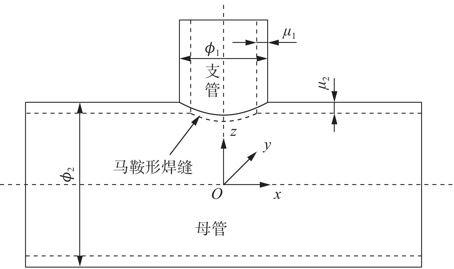
将马鞍形焊缝抽象为两个圆柱体相交形成的空间曲线. 以母管和支管轴线的交点为原点建立O-xyz坐标系,z轴与支管轴线重合,x轴与母管轴线重合,y轴可根据右手法则确定,如图1所示.
${\phi _{\text{1}}}$ ,${\mu _{\text{1}}}$ 分别是支管的直径与壁厚,${\phi _{\text{2}}}$ ,${\mu _{\text{2}}}$ 分别是母管的直径与壁厚.将曲线分别向xOy面和yOz面投影可得描述焊缝一般方程为
$$ \left\{ {\begin{array}{*{20}{c}} {{x^2} + {y^2} = {{\left( {\dfrac{{{\phi _1}}}{2}} \right)}^2}} \\ {{y^2} + {z^2} = {{\left( {\dfrac{{{\phi _2}}}{2}} \right)}^2}} \end{array}} \right. $$ (1) 由式(1)描述的焊缝方程难以直接描述每个变量的变化情况,因此将上式转化为以支管旋转变量
$\theta $ 为参数的函数.$\theta $ 表示支管轴线剖切面绕$z$ 轴逆时针旋转相对于$yOz$ 平面的夹角,取值范围为$ \left[ {{0,2{\text{π}} }} \right] $ . 在$t$ 时刻,焊缝上点的位置坐标$ {\left[ {{x_t}}\;{{y_t}}\;{{z_t}} \right]^{\text{T}}} $ 可表示为$$ \left[ {\begin{array}{*{20}{c}} {{x_t}} \\ {{y_t}} \\ {{z_t}} \end{array}} \right] = \left[ {\begin{array}{*{20}{c}} {\cos \theta }&{ - \sin \theta }&0 \\ {\sin \theta }&{\cos \theta }&0 \\ 0&0&1 \end{array}} \right]\left[ {\begin{array}{*{20}{c}} x \\ y \\ z \end{array}} \right] $$ (2) 由式(1) ~ 式(2)可得支管直径为
${\phi _{\text{1}}}$ ,母管直径为${\phi _{\text{2}}}$ 相贯形成的马鞍形焊缝上点的坐标描述为$$ \left\{ {\begin{array}{*{20}{l}} {{x_t} = \dfrac{{{\phi _1}}}{2}\cos \theta } \\ {{y_t} = \dfrac{{{\phi _1}}}{2}\sin \theta } \\ {{z_t} = \sqrt {{{\left( {\dfrac{{{\phi _2}}}{2}} \right)}^2} - {{\left( {\dfrac{{{\phi _1}}}{2}} \right)}^2}\cos {\theta ^2}} } \end{array}} \right. $$ (3) 2. 机器人结构设计
根据式(3)分析机器人需要通过圆周运动、支管径向运动、z轴相贯线高度调整运动实现马鞍形曲线轨迹,因此需要3个自由度. 在焊接过程中焊枪的姿态也是影响焊接质量的重要因素,因而需要再增加1个自由度,实现在焊接过程中对焊枪姿态进行实时调整. 多支管共母管的相贯构件相对机器人本体而言,质量较大,从工装成本及方便调整角度考虑,采用工件静止,机器人通过编程控制做相对运动到达预期的马鞍形相贯线轨迹及焊接姿态的形式.
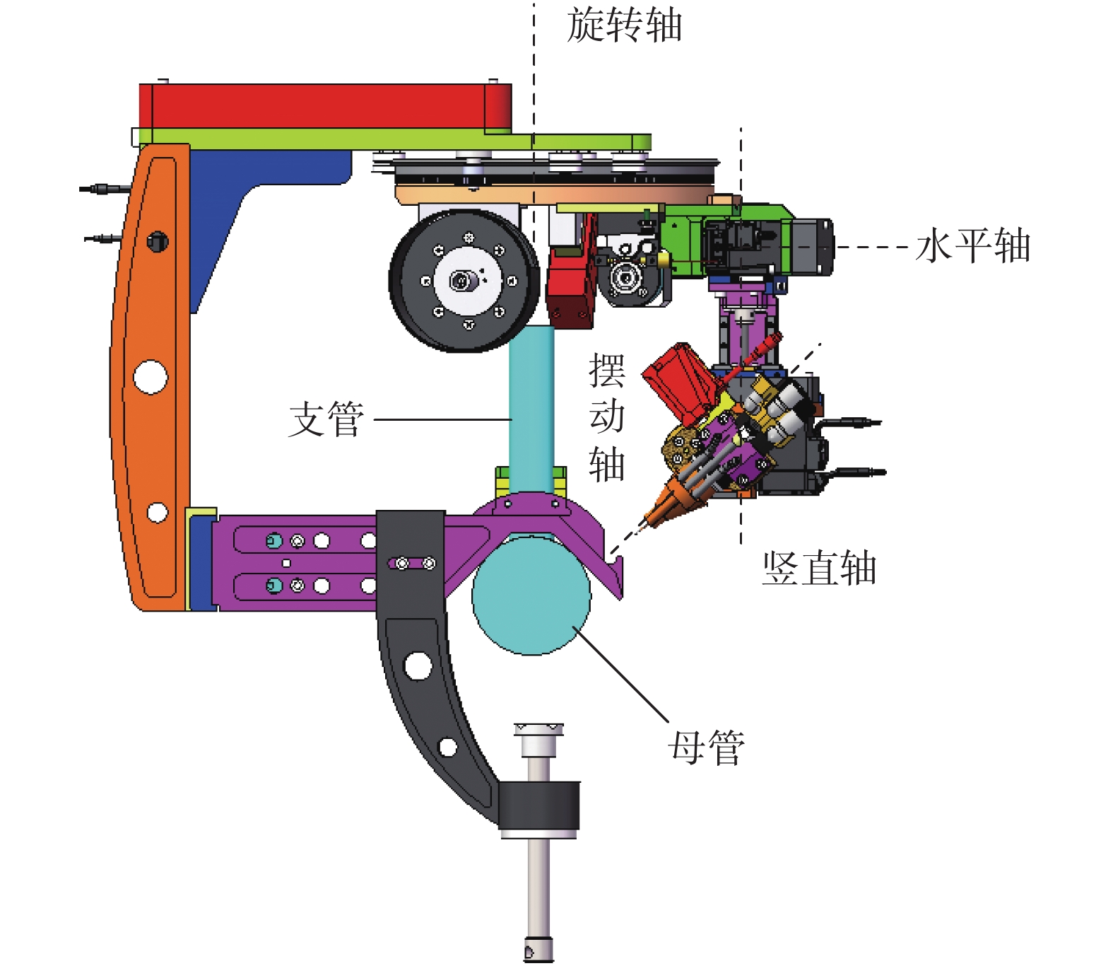
基于上述分析考虑,为了实现马鞍形焊缝的全位置高质量焊接采用了如图2所示的结构形式,其中1轴和4轴为旋转轴,2轴和3轴为平移轴.
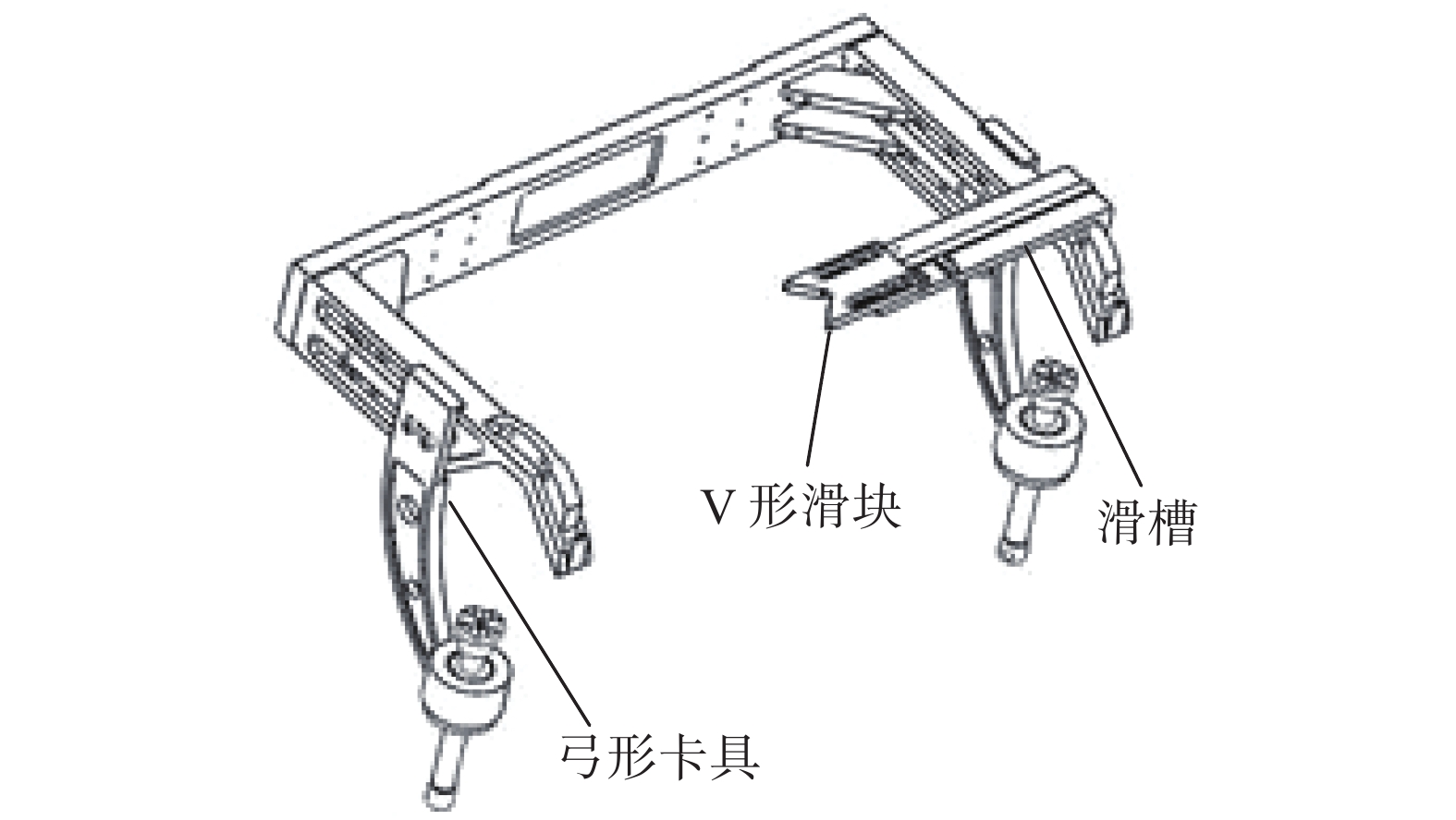
机器人装夹与定位装置如图3所示. 在马鞍形焊缝的焊接过程中,机器人定位非常关键,既要满足焊接过程中牢固可靠、定位准确,又要考虑非结构环境状态下的焊接工艺,同时还要兼顾机器人结构设计的合理性[6]. 工作过程中,首先通过弓形夹具与螺纹导杆将母管固定锁紧,通过调节V形滑块使其与支管外壁紧密贴合,保证支管轴心与机器人旋转轴线重合. 滑块安装在滑槽上通过调节其位置可实现对不同直径支管的轴心调节.
3. 机器人运动学分析
3.1 连杆坐标系建立
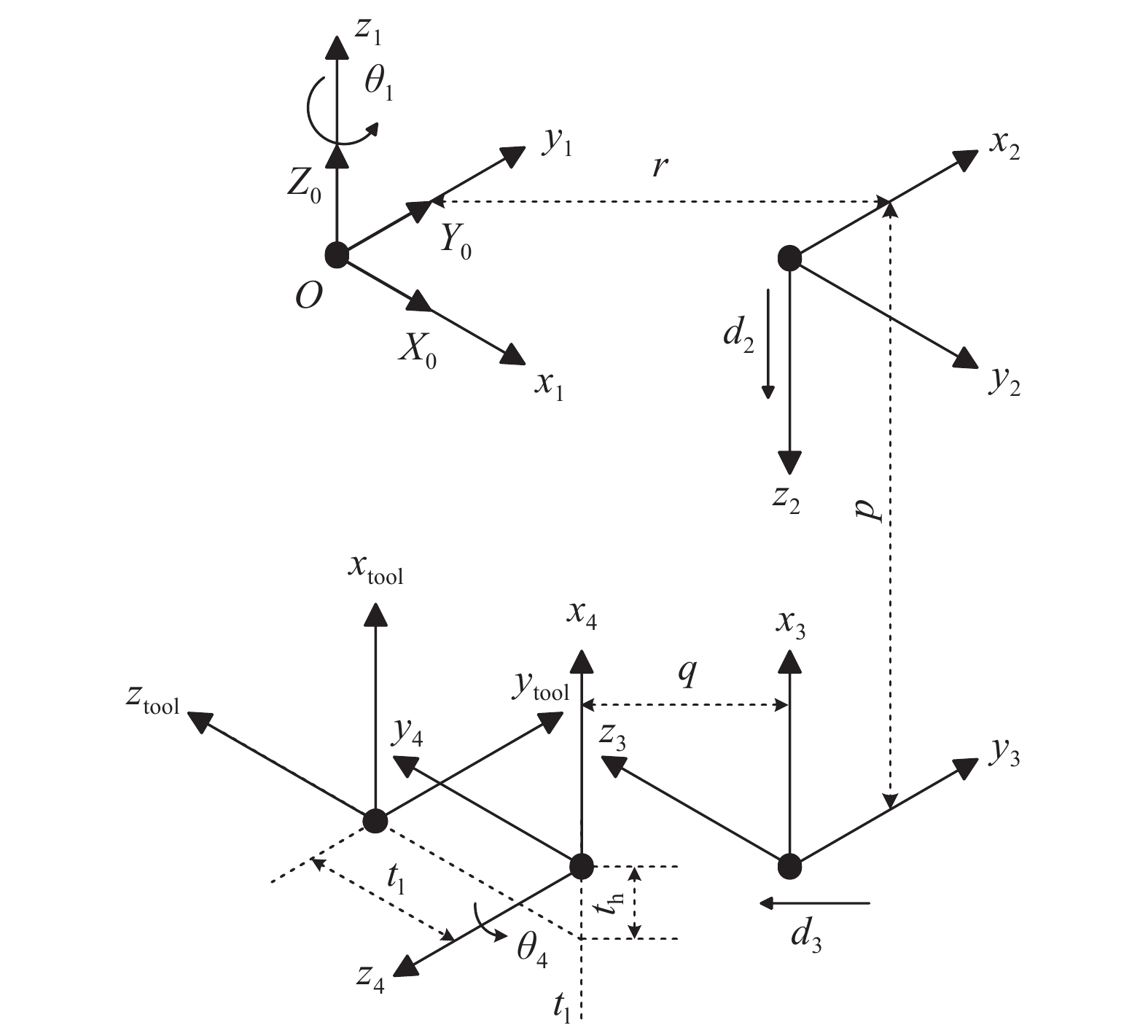
运动学分析是机器人轨迹规划和运动控制的基础[7]. 机器人的关节1和4做旋转运动,可将其简化为绕各自中心轴线做旋转运动的旋转副,其中关节1的旋转范围为−360°~360°,关节4的旋转范围为−10°~90°;关节2和3做平移运动,可简化为沿各自导轨方向的移动副,移动行程为0~75 mm. 根据标准D-H参数法,将关节旋转或平移的方向设为z轴正方向,在每个杆件上建立坐标系{i}. 固连于机器人基座(连杆0)上的坐标系为{0},该坐标系是固定不动的,在研究运动学过程中将其作为参考坐标系,设定参考坐标系{0}与连杆1的坐标系{1}重合,如图4所示.
根据机器人结构参数并结合图4可以很直观的建立如表1所示的D-H参数表.
表 1 机器人各连杆D-H参数Table 1. D-H parameters of robot links连杆转角
${\alpha _{i - 1} }/(^{\circ})$连杆长度
${a_{i - 1}}/\rm mm$连杆偏距
${d_i}/\rm mm$关节变量
θi /(°)0 0 0 ${\theta _1}$ 180 $r$ $ - {d_2}$ −90 90 $p$ $ - {d_3}$ −90 90 0 $q$ ${\theta _4}$ 3.2 机器人正运动学分析
机器人正运动学是通过机器人连杆参数,利用齐次矩阵变化求得机器人末端工具在其基坐标系下的位姿表述,其坐标系间变化通式为式(4)中Rot和Trans分别表示旋转和平移变化[8].
$$ T_i^{i - 1} = {\rm{Rot}}(x,{\alpha _{i - 1}}){\rm{Trans}}(x,{a_{i - 1}}){\rm{Rot}}(z,{\theta _i}){\rm{Trans}}(z,{d_i}) $$ (4) 根据D-H连杆坐标系及式(4),可得连杆1在机器人参考坐标系{0}下的位姿描述为
$$ {\boldsymbol{T_1^0}} = \left[ {\begin{array}{*{20}{c}} {\cos {\theta _1}}&{ - \sin {\theta _1}}&0&0 \\ {\sin {\theta _1}}&{\cos {\theta _1}}&0&0 \\ 0&0&1&0 \\ 0&0&0&1 \end{array}} \right] $$ (5) 同理可得其余连杆坐标系在其上一级坐标系,即
$$ {\boldsymbol{T_2^1}}{\text{ = }}\left[ {\begin{array}{*{20}{c}} 0&1&0&r \\ 1&0&0&0 \\ 0&0&{ - 1}&{ - {d_2}} \\ 0&0&0&1 \end{array}} \right] $$ (6) $$ {\boldsymbol{T_3^2}}{\text{ = }}\left[ {\begin{array}{*{20}{c}} 0&1&0&0 \\ 0&0&{ - 1}&{ - {d_3}} \\ { - 1}&0&0&p \\ 0&0&0&1 \end{array}} \right] $$ (7) $$ {\boldsymbol{T_4^3}}{\text{ = }}\left[ {\begin{array}{*{20}{c}} {\cos {\theta _4}}&{ - \sin {\theta _4}}&0&0 \\ 0&0&{ - 1}&0 \\ {\sin {\theta _4}}&{\cos {\theta _4}}&0&q \\ 0&0&0&1 \end{array}} \right] $$ (8) 焊枪末端坐标系在关节4坐标系中的位姿描述为
$$ {\boldsymbol{T}}_{{\bf{tool}}}^{\boldsymbol{4}}{\text{ = }}\left[ {\begin{array}{*{20}{c}} 1&0&0&{ - t_{\rm{h}}} \\ 0&0&1&{t_{\rm{l}}} \\ 0&{ - 1}&0&0 \\ 0&0&0&1 \end{array}} \right] $$ (9) 将上述变化矩阵连续相乘可得到焊枪末端点TCP坐标系{tool}在机器人基坐标系{0}下的位姿,即
$$ {\boldsymbol{T}}_{{\bf{tool}}}^{\boldsymbol{0}} = \left[ {\begin{array}{*{20}{c}} R&T \\ 0&1 \end{array}} \right] $$ (10) $$ R = \left[ {\begin{array}{*{20}{c}} { - \cos {\theta _1}\sin {\theta _4}}&{ - \sin {\theta _1}}&{ - \cos {\theta _1}\cos {\theta _4}} \\ { - \sin {\theta _1}\sin {\theta _4}}&{\cos {\theta _1}}&{ - \sin {\theta _1}\cos {\theta _4}} \\ {\cos {\theta _4}}&0&{ - \sin {\theta _4}} \end{array}} \right] $$ (11) $$ T = \left[ {\begin{array}{*{20}{c}} {\left( {r - q - {d_3} - t_{\rm{l}}\cos {\theta _4} + t_{\rm{h}}\sin {\theta _4}} \right)\cos {\theta _1}} \\ {\left( {r - q - {d_3} - t_{\rm{l}}\cos {\theta _4} + t_{\rm{h}}\sin {\theta _4}} \right)\sin {\theta _1}} \\ { - (p + {d_2} + t_{\rm{l}}\sin {\theta _4} + t_{\rm{h}}\cos {\theta _4})} \end{array}} \right] $$ (12) 上述公式即为正运动学表达式求解结果,可以通过给定机器人各关节变量的值来得到机器人焊枪TCP的位置和姿态.
3.3 机器人逆运动学分析
机器人运动学逆问题求解是通过已知机器人末端TCP的位姿来求解机器人各个运动关节变量值的过程[9]. 求解机器人运动学逆解方法较多,常见的方法有代数法和几何法[10]. 结合本机器人结构特点,采用解析法对机器人各连杆关节变量
${\theta _1}$ ,${d_2}$ ,${d_3}$ ,${\theta _4}$ 进行求解.设焊枪末端在基坐标系下的位姿矩阵为
$$ {\boldsymbol{T}}_{{\bf{tool}}}^{\boldsymbol{0}}{\text{ = }}\left[ {\begin{array}{*{20}{c}} {{n_x}}&{{o_x}}&{{a_x}}&{{p_x}} \\ {{n_y}}&{{o_y}}&{{a_y}}&{{p_y}} \\ {{n_z}}&{{o_z}}&{{a_z}}&{{p_z}} \\ 0&0&0&1 \end{array}} \right] $$ (13) 由于位姿矩阵为正交矩阵,其转置矩阵和逆矩阵相等,因此
${\boldsymbol{T}}_{\boldsymbol{1}}^{\boldsymbol{0}}$ 的逆矩阵为$$ {\boldsymbol{T_0^1}}{\text{ = }}\left[ {\begin{array}{*{20}{c}} {\cos {\theta _1}}&{ - \sin {\theta _1}}&0&0 \\ {\sin {\theta _1}}&{\cos {\theta _1}}&0&0 \\ 0&0&1&0 \\ 0&0&0&1 \end{array}} \right] $$ (14) 首先进行
${\theta _1}$ 的求解,将式(13)与式(14)相乘可得式(15).$$ {\boldsymbol{T}}_{{\bf{tool}}}^{\boldsymbol{1}} = \left[ {\begin{array}{*{20}{c}} {{m_x}}&{{l_x}}&{{q_x}}&{{k_x}} \\ {{m_y}}&{{l_y}}&{{q_y}}&{{k_y}} \\ {{n_z}}&{{o_z}}&{{a_z}}&{{p_z}} \\ 0&0&0&1 \end{array}} \right] $$ (15) $$ \left\{\begin{array}{l} {m_x} = {n_x} \cos {\theta _1} + {n_y} \sin {\theta _1} \hfill \\ {m_y} = {n_y} \cos {\theta _1} - {n_x} \sin {\theta _1} \hfill \\ {l_x} = {o_x} \cos {\theta _1} + {o_y} \sin {\theta _1} \hfill \\ {l_y} = {o_y} \cos {\theta _1} - {o_x} \sin {\theta _1} \hfill \\ {q_x} = {a_x} \cos {\theta _1} + {a_y} \sin {\theta _1} \hfill \\ {q_y} = {a_y} \cos {\theta _1} - {a_x} \sin {\theta _1} \hfill \\ {k_x} = {p_x} \cos {\theta _1} + {p_y} \sin {\theta _1} \hfill \\ {k_y} = {p_y} \cos {\theta _1} - {p_x} \sin {\theta _1} \hfill \end{array} \right. $$ (16) 由式(6) ~ 式(9)可求得.
$$ {\boldsymbol{T}}_{{\bf{tool}}}^{\boldsymbol{1}}{\text{ = }}\left[ {\begin{array}{*{20}{c}} {R_{{\rm{tool}}}^1}&{P_{{\rm{tool}}}^1} \\ 0&1 \end{array}} \right] $$ (17) $$ R_{{\rm{tool}}}^1 = \left[ {\begin{array}{*{20}{c}} { - \sin {\theta _4}}&0&{ - \cos {\theta _4}} \\ 0&1&0 \\ {\cos {\theta _4}}&0&{ - \sin {\theta _4}} \end{array}} \right] $$ (18) $$ P_{{\rm{tool}}}^1 = \left[ {\begin{array}{*{20}{c}} {r - q - {d_3} - t_{\rm{l}} \cos {\theta _4} + t_{\rm{h}} \sin {\theta _4}} \\ 0 \\ { - ({d_2} + p + t_{\rm{l}} \sin {\theta _4} + t_{\rm{h}} \cos {\theta _4})} \end{array}} \right] $$ (19) 通过式(15)与式(17)中(1,0)项对应相等可得式(20).
$$ {n_y} \cos {\theta _1} - {n_x} \sin {\theta _1} = 0 $$ (20) 通过三角函数公式代换化简上式可得式(21).
$$ {\theta _1} = a\tan 2({n_y},{n_x}) + k{\text{π}} ,k = \left\{ {0,} \right.\left. { \pm 1} \right\} $$ (21) 从式(21)可以看出,
${\theta _1}$ 共有3组解,因此需要通过${\theta _1}$ 的正负限位值及x轴的姿态判断该时刻机器人轴1所在象限.(1)当
$ {n_x} = - \cos {\theta _1}\sin {\theta _4} > 0 $ 时,$ {\theta _1} \in [ - {\text{π}} /2,{\text{π}} /2] $ 时,即$$ {\theta _1} = a\tan 2({n_y},{n_x}) $$ (22) (2)当
$ {n_x} = - \cos {\theta _1}\sin {\theta _4} < 0 $ ,$ {n_y} = - \sin {\theta _1}\sin {\theta _4} > 0 $ 时,$ {\theta _1} \in [{\text{π}} /2,{\text{π}} ] $ ,即$$ {\theta _1} = a\tan 2({n_y},{n_x}) + {\text{π}} $$ (23) (3)当
$ {n_x} = - \cos {\theta _1}\sin {\theta _4} < 0 $ ,$ {n_y} = - \sin {\theta _1}\sin {\theta _4} < 0 $ 时,$ {\theta _1} \in [ - {\text{π}} , - {\text{π}} /2] $ ,即$$ {\theta _1} = a\tan 2({n_y},{n_x}) - {\text{π}} $$ (24) 求解
${\theta _4}$ ,通过式(15)与式(17)中(2,0)项对应相等可得式(25).$$ {\theta _4} = a\cos ({n_z}) $$ (25) 求解
${d_2}$ ,通过式(15)与式(17)中(2,0),(2,2),(2,3)项对应相等可得式(26).$$ \left[ {\begin{array}{*{20}{c}} {{n_z}} \\ {{p_z}} \\ {{a_z}} \end{array}} \right] = \left[ {\begin{array}{*{20}{c}} {\cos {\theta _4}} \\ { - ({d_2} + p + t_{\rm{l}} \sin {\theta _4} + t_{\rm{h}} \cos {\theta _4})} \\ { - \sin {\theta _4}} \end{array}} \right] $$ (26) 通过化简上式可求得式(27).
$$ {d_2} = - ({p_z} + p + t_{\rm{h}} {n_z} - t_{\rm{l}} {a_z}) $$ (27) 求解
${d_3}$ ,通过式(15)与式(17)中(0,3)项对应相等可得式(28).$$ {d_3} = - (q + t_{\rm{l}} {n_z} + t_{\rm{h}} {a_z} + {p_x}\cos {\theta _1} + {p_y}\sin {\theta _1} - r) $$ (28) 式(21)、式(25)、式(27)和式(28)即为机器人运动学逆解的表达式,给出机器人当前位姿带入这些表达式即可求得对应的各关节变量的值.
4. 运动学仿真与样机验证
为了验证机器人样机的可靠性和实用性,需要进行焊接试验. 在焊接试验前,先通过运动学仿真动态模拟焊枪的运动轨迹来验证所规划的轨迹及运动学模型的正确性. 文中利用MATLAB软件强大的可视化仿真功能对机器人运动学进行仿真验证.
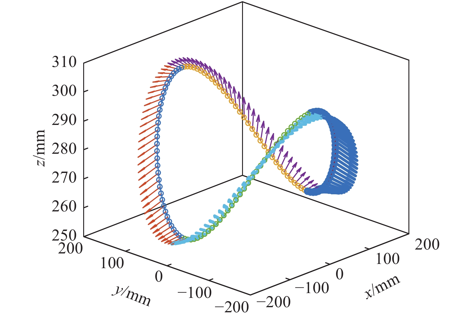
焊接支管筒体的直径
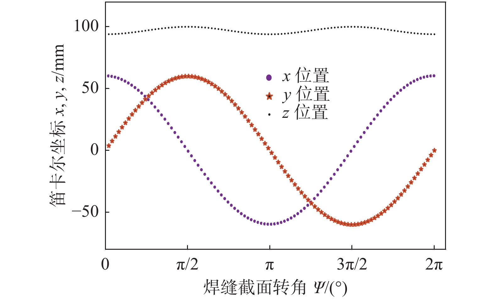
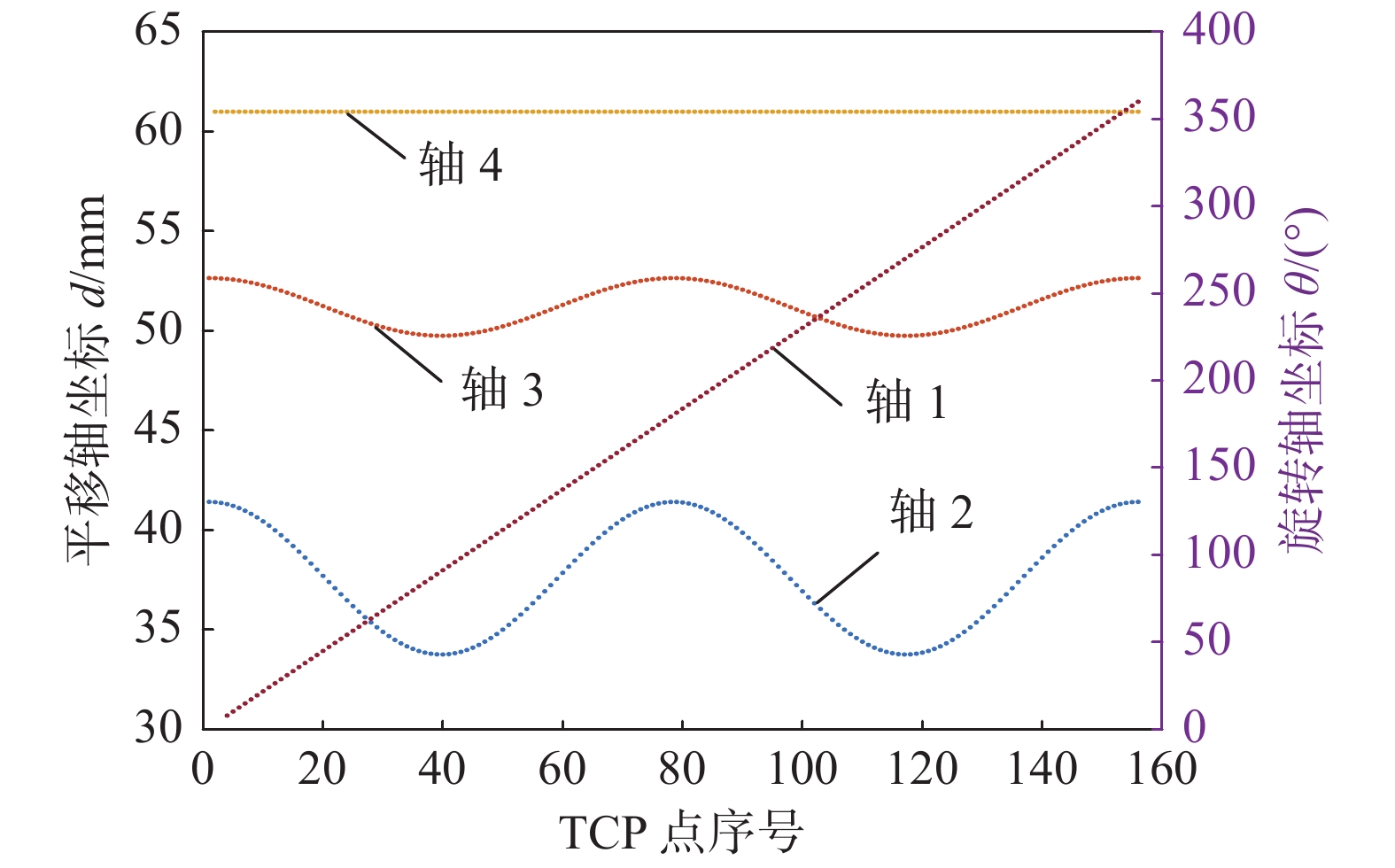
${\phi _{\text{1}}}$ = 60 mm,${\mu _{\text{1}}}$ = 10 mm,母管筒体直径${\phi _{\text{2}}}$ = 300 mm,${\mu _{\text{2}}}$ = 40 mm. 按照式(3)建立的马鞍形焊缝数学模型对机器人TCP位置及姿态进行规划,文中给定的轨迹中焊枪末端指向相贯线焊缝坐标系的z轴方向[11],如图5所示. 焊枪末端沿该轨迹运动时,其各个位置分量如图6所示,从图6可以看出,x位置按三角余弦函数变化,y位置按照正弦规律变化,z位置按照上坡-下坡-上坡-下坡的规律变化,符合马鞍线的几何特征.为了控制焊枪沿着马鞍形焊缝移动需要计算出焊枪到达该焊点位置时各关节所需的运动量. 通过逆运动学表达式求解得到焊枪轨迹对应的各关节序列值如图7所示.
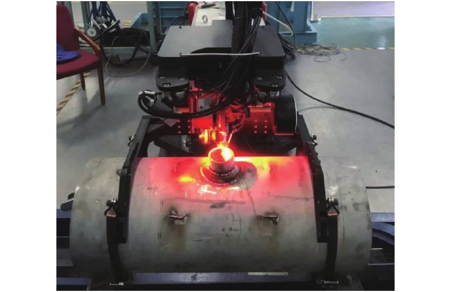
从图7可以看出,各关节值变化连续平滑,验证了运动学算法的正确性. 为了验证实际工作效果,制作了图8所示的样机对母材为022Cr19Ni10奥氏体不锈钢采用TIG焊工艺进行焊接试验. 选用直径为1.2 mm的ERNiCrFe-7A焊丝,保护气体为氩气. 焊接工艺参数如表2所示,焊接成形情况如图9所示.
表 2 TIG焊接工艺参数Table 2. TIG welding parameters焊接电流
I/A电弧电压
U/V送丝速度
vs/(mm·min−1)焊接速度
v/(mm/min−1)气体流量
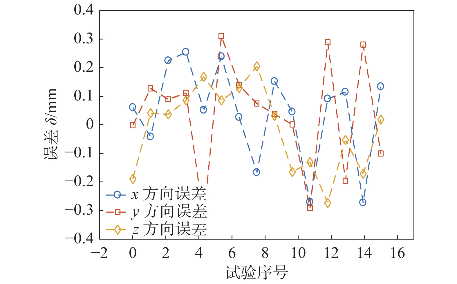
Q/(L·min−1)220 38 800 130 15 从图9可以看出,焊缝成形致密美观,无缺陷,证明了机器人结构合理,装夹定位准确可靠,且旋转轴1的中心线与支管轴线吻合良好,可以实现马鞍形焊缝各个位置的实时位姿焊接控制. 通过采集焊枪焊接过程中各关节值并将其带入正运动学表达式即可求得实际焊枪轨迹,将其与规划的理论轨迹进行比较就可得出焊枪精度,如图10所示. 从图10可以看出,在焊接过程中焊枪精度在±0.35 mm以内,满足焊接机器人对精度的要求.
5. 结论
(1) 针对马鞍形相贯线焊缝结构特点,设计了一种管外锚固式自适应一定范围直径的支管定心通用型四轴焊接机器人.
(2) 运用D-H参数法建立机器人连杆坐标系,对正逆运动学表达式进行求解,并通过MATLAB软件仿真验证了机器人运动学模型的正确性.
(3) 制作了机器人样机进行焊接试验,机器人装夹牢固,定位准确,焊接完成后焊缝成形致密美观.
-
表 1 机器人各连杆D-H参数
Table 1 D-H parameters of robot links
连杆转角 ${\alpha _{i - 1} }/(^{\circ})$ 连杆长度 ${a_{i - 1}}/\rm mm$ 连杆偏距 ${d_i}/\rm mm$ 关节变量
θi /(°)0 0 0 ${\theta _1}$ 180 $r$ $ - {d_2}$ −90 90 $p$ $ - {d_3}$ −90 90 0 $q$ ${\theta _4}$  下载: 导出CSV
表 2 TIG焊接工艺参数
Table 2 TIG welding parameters
焊接电流
I/A电弧电压
U/V送丝速度
vs/(mm·min−1)焊接速度
v/(mm/min−1)气体流量
Q/(L·min−1)220 38 800 130 15
下载: 导出CSV
-
[1] 王丽, 龚君, 赵寿宽, 等. 便携式相贯线切割焊接一体机的设计与实际应用[J]. 科技与创新, 2020, 165(21): 158 − 159. Wang Li, Gong Jun, Zhao Shoukuan, et al. Design and practical application of portable intersecting wire cutting and welding machine[J]. Science and Technology & Innovation, 2020, 165(21): 158 − 159.
[2] Liu Y, Tian X. Robot path planning with two-axis positioner for non-ideal sphere-pipe joint welding based on laser scanning[J]. The International Journal of Advanced Manufacturing Technology, 2019, 105(1-4): 1295 − 1310. doi: 10.1007/s00170-019-04344-3
[3] Xue Lianghao, Wei Min, Yang Tao, et al. A new welding robot for intersected weld of pipes used in large pressure vessels[C]//MATEC Web of Conferences. EDP Sciences, 2019, 267: 01006.
[4] 危文灏, 贠超, 宋德政, 等. 机器人多层多道焊接的路径规划[J]. 机器人, 2014, 36(3): 257 − 262,270. Wei Wenhao, Yun Chao, Song Dezheng, et al. Path planning for robotic multi-path/multi-layer welding[J]. Robot, 2014, 36(3): 257 − 262,270.
[5] 李向春, 毛志伟, 陈记超, 等. 新型相贯线焊接机器人设计与研究[J]. 热加工工艺, 2019, 48(5): 226 − 230. Li Xiangchun, Mao Zhiwei, Chen Jichao, et al. Design and research of a new type of intersecting line welding robot[J]. Hot Working Technology, 2019, 48(5): 226 − 230.
[6] 李东洁, 李潜, 王世伟, 等. 全位置相贯线自动焊接新型焊枪设计[J]. 焊接学报, 2018, 39(3): 117 − 119,123. doi: 10.12073/j.hjxb.2018390081 Li Dongjie, Li Qian, Wang Shiwei, et al. Design of a new type of welding torch for automatic welding of all-position intersecting lines[J]. Transactions of the China Welding Institution, 2018, 39(3): 117 − 119,123. doi: 10.12073/j.hjxb.2018390081
[7] 丛志文, 王好臣, 高茂源, 等. KR16-2机器人运动学分析及路径规划[J]. 机床与液压, 2020, 48(15): 50 − 55. doi: 10.3969/j.issn.1001-3881.2020.15.011 Cong Zhiwen, Wang Haochen, Gao Maoyuan, et al. Kinematics analysis and path planning of KR16-2 robots[J]. Machine Tool & Hydraulics, 2020, 48(15): 50 − 55. doi: 10.3969/j.issn.1001-3881.2020.15.011
[8] 吕志忠, 张成维, 钟功祥, 等. 一种四足磁吸附爬壁机器人运动学分析及仿真[J]. 四川大学学报(工程科学版), 2020, 52(2): 121 − 129. Lyu Zhizhong, Zhang Chengwei, Zhong Gongxiang, et al. Kinematics analysis and simulation of a quadruped magnetic sdsorption wall-climbing robot[J]. Journal of Sichuan University(Engineering Science Edition), 2020, 52(2): 121 − 129.
[9] 吉阳珍, 侯力, 罗岚, 等. 基于组合优化算法的6R机器人逆运动学求解[J]. 中国机械工程, 2021, 32(10): 1222 − 1232. doi: 10.3969/j.issn.1004-132X.2021.10.011 Ji Yangzhen, Hou Li, Luo Lan, et al. Solution of inverse kinematics for 6R robots based on combinatorial optimization algorithm[J]. China Mechanical Engineering, 2021, 32(10): 1222 − 1232. doi: 10.3969/j.issn.1004-132X.2021.10.011
[10] 宋德政, 贠超, 危文灏. 管管相贯的焊接坡口模型分析[J]. 机械设计与制造, 2013(11): 171 − 174. doi: 10.3969/j.issn.1001-3997.2013.11.052 Song Dezheng, Yun Chao, Wei Wenhao. Welding groove model analysis of the intersecting pipe[J]. Machinery Design & Manufacture, 2013(11): 171 − 174. doi: 10.3969/j.issn.1001-3997.2013.11.052
[11] Liu Y, Liu Y, Tian X. Trajectory and velocity planning of the robot for sphere-pipe intersection hole cutting with single-Y welding groove[J]. Robotics and Computer-Integrated Manufacturing, 2019, 56: 244 − 253. doi: 10.1016/j.rcim.2018.10.005


计量
- 文章访问数: 434
- HTML全文浏览量: 86
- PDF下载量: 51
