
Nondestructive testing of austenitic welds using method of ultrasonic array
-
摘要: 在焊接热循环作用下,奥氏体不锈钢焊缝内部呈粗大柱状晶组织,且其取向在焊缝不同区域呈各向异性.针对粗大柱状晶引起的超声波散射和晶粒取向不同导致的声束偏折等问题,进行奥氏体不锈钢焊缝超声阵列检测方法研究.针对超声阵列获得全矩阵数据,发展了一种基于时间反转算子分解的超声阵列信号去噪方法.利用射线追踪法,研究了各向异性介质中超声波传播路径确定方法,并将其应用于奥氏体不锈钢焊缝超声阵列全聚焦成像的声束偏折校正.开展了奥氏体不锈钢焊缝超声阵列检测试验研究.结果表明,基于时间反转算子分解方法可以很好剔除检测信号中的散射噪声,凸显特征回波信息,可将全聚焦成像的信噪比提高10 dB,而波束偏折校正则可以提高超声阵列全聚焦成像中缺陷定位的精度.Abstract: Under the action of welding thermal cyclic load, the internal peritectic structure of austenitic stainless steel weld is coarse columnar crystal, and its orientation is anisotropic in different areas of the weld. The nondestructive testing of austenitic stainless steel welds is conducted using method of ultrasonic array for the ultrasonic scattering caused by coarse columnar crystals and the sound beam deflection caused by different grain orientations. A signal analysis method based on decomposition of the time-reversal operator is developed for noise reduction processing of ultrasound full matrix data. Using ray tracing method, the ultrasonic wave propagation path determination method in anisotropic media was investigated and applied to the correction of beam deflection for ultrasonic array total focus imaging of austenitic stainless steel welds. Nondestructive testing of austenitic stainless steel welds was conducted using ultrasonic array, and the results showed that the time-reversal operator-based decomposition method was effective for the suppression of scattering noise in the detection signal and highlight the echoes from defects, which can improve the signal-to-noise ratio of full-focus imaging by 10 dB, moreover the beam deflection correction can improve the accuracy of defect localization in total focus imaging of ultrasonic arrays.
-
0. 序言
由于具有优良的抗腐蚀性、抗氧化性及低温韧性等特点,奥氏体不锈钢被广泛应用于石油、化工、船舶、机械制造和核电等重大基础行业关键部件[1-2].在这些关键部件中,多采用焊接方式实现奥氏体不锈钢结构间的连接,而焊缝是整个部件的薄弱环节.与其它材料的焊接结构相比,奥氏体不锈钢焊缝的组织结构有其独特性.奥氏体不锈钢焊缝在凝固时未发生相变,其内部组织在焊接热循环作用下成长为粗大的柱状晶组织.这些柱状晶在局部区域内具有一定的取向,但在焊缝不同区域中其取向会发生明显的变化,使焊缝在整体上呈现出各向异性和不均匀性[3-4].当超声波在奥氏体不锈钢焊缝中传播时,在粗大的柱状晶处将产生散射衰减和林状回波,极大地降低了超声波的信噪比;同时弹性各向异性也会导致声束出现畸变、曲线传播等现象,严重影响超声波检测的定位精度和检测灵敏度[5-6].奥氏体不锈钢焊缝的上述特点,大大增加了超声波在焊缝中传播的复杂性和检测的难度.奥氏体不锈钢焊缝内部复杂的组织结构,导致传统超声无损检测方法难以发挥其优势.提高奥氏体焊缝缺陷超声检测的准确性和有效性,已成为国内外无损检测领域专家关注的热点和难点问题.
各向异性介质中超声波传播速度的各向异性和曲线传播特点,使得基于传统各向同性介质中超声波均匀速度直线传播的缺陷定位方法不再适用.为此,国内外学者利用Christoffel方程推导出超声波相速度和群速度随入射声波方向和晶粒取向的变化关系,并通过试验验证了各向异性材料中超声波传播速度的各向异性特点 [7-8].射线追踪算法是一种计算各向异性介质中声线传播路径的常用方法[9].而最短路径法又是其中一种计算两点间声波传播时间的高效方法[10-11].目前常用的最短路径算法有Dijkstra算法和A*算法两种.Zhang等人[12]利用Dijkstra算法对奥氏体不锈钢焊缝进行射线追踪实现了对焊缝中缺陷的准确定位.Dijkstra算法搜索没有方向性,因此其搜索范围比较大,计算效率较低[13].与Dijkstra算法相比,A*法搜索效率较高,但无法保证搜索到的结果是全局最优解[14].因此,在各向异性介质中声线传播路径确定中,需要兼顾射线追踪算法的计算效率和寻优的全局性.
由于超声波在粗晶材料中产生的散射噪声属于结构噪声,在检测系统及超声探头确定的情况下,这种噪声的频率组成是非时变的,常规信号平均技术无法用于该类噪声的抑制.针对粗晶材料中超声波传播产生的散射噪声问题,国内外学者将多种信号处理方法,如小波变换、希尔伯特-黄变换等[15-16],应用于超声信号降噪处理,取得了一定效果,但这些方法未利用晶粒散射噪声与缺陷回波的差异性,使得其降噪效果和效率均较低.时间反转算子分解方法(decomposition of the time-reversal operator,DORT)是一种将时间反转算子和奇异值分解相结合的信号处理方法[17-18].基于阵列获取的大量检测数据,该方法利用时间反转算子构造的奇异值分布,不仅可以有效剔除信号中的噪声,还能保留与噪声频带相混叠的有用信息[19]. Deng等人[20-21]将时间反转算子分解方法应用于管道超声导波检测信号处理,提高了检测信号的信噪比和成像精度.Villaverde等人[22-23]将时间反转算子分解应用于奥氏体-铁素体双相不锈钢试件的超声阵列检测信号的成像处理中,相较于传统合成孔径成像方法与传统全聚焦成像方法,其成像信噪比分别提高了21和30 dB.根据超声信号时间反转算子分解后缺陷信号的特征向量矩阵,肖琨[24]调整了超声相控阵探头的延时法则,提高了超声检测中缺陷定位精度.Cunningham等人[25]将时间反转算子分解方法应用于奥氏体不锈钢试件的超声阵列检测信号处理中,提高了缺陷成像的信噪比.综上所述,时间反转算子分解法由于能够保留与噪声信号频带相混叠的有用信号的特点,更适用于超声检测信号中散射噪声的剔除.但时间反转算子分解法的降噪效果与选用的奇异值数量有关,使用过程中进一步研究噪声及有用信息对应的奇异值范围.
针对粗大柱状晶引起的超声波散射和晶粒取向不同导致的声束偏折,进行奥氏体不锈钢焊缝超声阵列检测方法研究.通过数值仿真研究了超声波在各向异性焊缝/介质中的传播,利用射线追踪法确定了各向异性介质中超声波传播路径,并将时间反转算子分解方法应用于奥氏体不锈钢焊缝超声阵列检测数据处理.在此基础上,提出了一种奥氏体不锈钢焊缝超声阵列成像方法.
1. 奥氏体不锈钢焊缝超声阵列检测方法
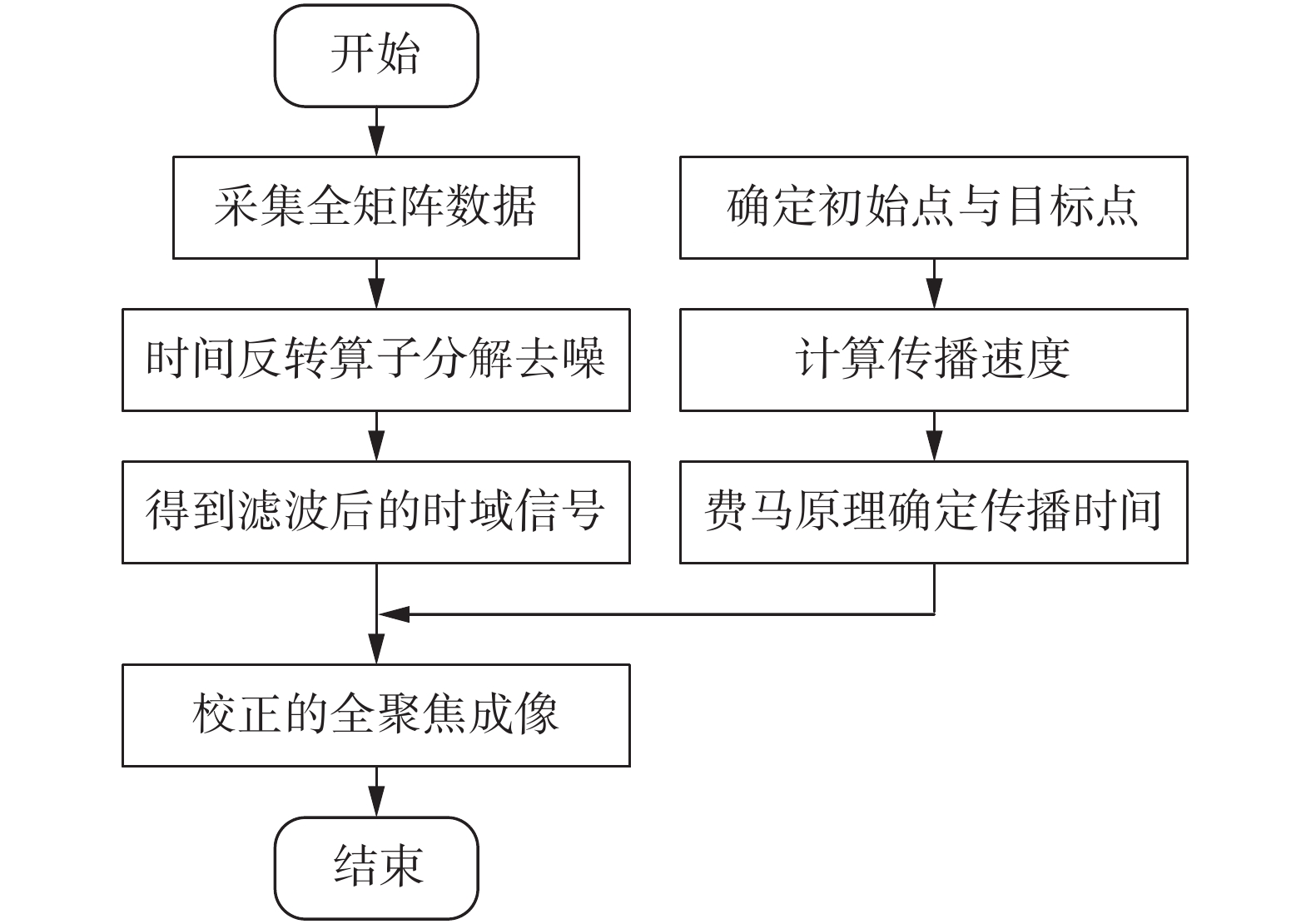
针对奥氏体不锈钢焊缝中各向异性、粗大晶粒引起的超声波散射和声束偏折问题,文中提出一种各向异性焊缝超声阵列检测方法,图1为方法的流程图.该方法的核心思想为:将射线追踪技术用于波束偏折的补偿,将时间反转算子分解方法用于超声波散射噪声的剔除.
1.1 射线追踪波束偏折补偿方法
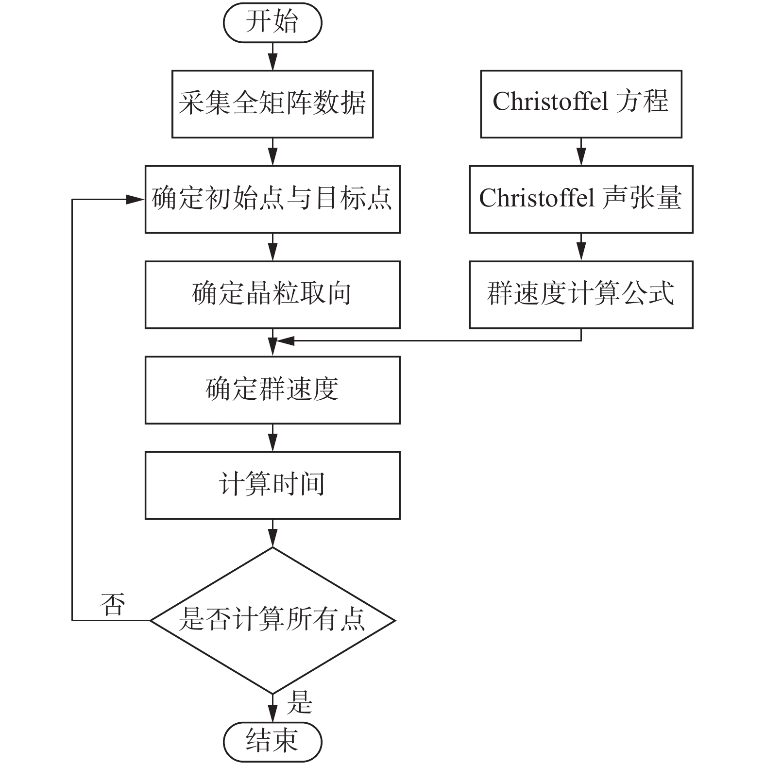
超声波在各向异性介质中传播时,不会沿直线传播,其传播路径与各异性介质的晶粒取向和超声波的入射方向有关.射线追踪方法根据各向异性介质中的Christoffel方程,得到其群速度和质点位移方向,可计算超声波的传播时间,进而得到超声波在各向异性介质中的传播路径.图2给出射线追踪的波束偏折补偿方法的流程图.
根据超声波在各向异性介质中传播的Christoffel方程,可以得出取决于晶体的对称性和波的传播方向Christoffel声张量Γil[9-11],即
$$ \left| {\begin{array}{*{20}{c}} {{\varGamma _{11}} - \rho {c^2}}&{{\varGamma _{12}}}&{{\varGamma _{13}}} \\ {{\varGamma _{12}}}&{{\varGamma _{22}} - \rho {c^2}}&{{\varGamma _{23}}} \\ {{\varGamma _{13}}}&{{\varGamma _{23}}}&{{\varGamma _{33}} - \rho {c^2}} \end{array}} \right| = 0 $$ (1) 式中:ρ表示密度;c表示波速;Γil表示Christoffel声张量.
求解行列式Γil的特征值λ和特征向量p,即可得到各向异性材料中的相速度和群速度.
$$ {\lambda _a} = \rho /m_a^2 $$ (2) $$ {v_a} = {p_a} $$ (3) 式中:
$ 1 \leqslant a \leqslant 3 $ ,p为极化矢量;m表示慢度矢量,即$ m = k/\omega $ .其中,k表示波数,$ \omega $ 表示角频率.相速度${c_{\rm{p}}}$ 可用慢度的倒数来表示,即$$ {c_{\rm{p}}} = 1/m $$ (4) 群速度Cga可用下式来表示,即
$$ {C_{{\rm{ga}}}} = \frac{1}{\rho }{C_{{\rm{ajkl}}}}{p_{\rm{j}}}{p_{\rm{k}}}{m_{\rm{l}}} $$ (5) 式中:Cαjkl表示弹性常数矩阵.p表示Christoffel声张量矩阵的特征向量.由上式可知,各向异性材料中超声波的相速度和群速度与超声波的入射方向有关.
在进行射线追踪时,首先确定初始点和目标点的位置.根据初始点和目标点之间的晶粒取向,按照式(4)和式(5)计算超声波的相速度和群速度.基于费马原理,超声波在介质中沿所需时间最短的路径传播,由此可以确定传播时间为
$$ t = \frac{{\sqrt {{{({x_{\rm{a}}} - {x_0})}^2} + {{({z_{\rm{a}}} - {z_0})}^2}} }}{{{c_1}}} + \frac{{\sqrt {{{({x_{\rm{a}}} - {x_i})}^2} + {{({z_{\rm{a}}} - {z_i})}^2}} }}{{{c_2}}} $$ (6) 式中:x0和z0表示初始点的横纵坐标值;xa和za表示与界面相交处的点的横纵坐标值;xi和zi分别表示目标点的横纵坐标值;c1为第一种介质中超声波的传播速度;c2为第二种介质中超声波的传播速度.
基于超声阵列采集的全矩阵数据,全聚焦成像方法(total focus imaging method)依据传播时间将全矩阵数据中对应时刻的幅值相叠加,实现检测区域内任意点的聚焦成像.在成像过程中,特定聚焦点(x,z)的幅值可表示为
$$ I(x,z) = \sum\limits_{i = 1}^N {\sum\limits_{j = 1}^N {{s_{ij}}} } ({t_{ij}}(x,z)) $$ (7) 式中:
$ t_{i j}(x, z) $ 为超声波从第i个阵元传播至(x,z)后,再传播回第j个阵元所用的时间.上式给出了各向同性介质中任意点的全聚焦成像幅值.在各向异性介质中,全聚焦成像中不同位置间的传播时间可表示为$$ {t_{ij}}(x,z) = \frac{{\sqrt {{{({x_i} - x)}^2} + {z^2}} + \sqrt {{{({x_j} - x)}^2} + {z^2}} }}{{{c_{ij}}({\phi _{ij}},\theta )}} $$ (8) 式中:速度c为变量;xi 表示激励阵元位置;xj表示接收阵元位置.基于式(8)确定的时间,可将全聚焦成像方法拓展应用于各向异性介质中缺陷成像.
1.2 基于时间反转算子分解的超声阵列去噪方法
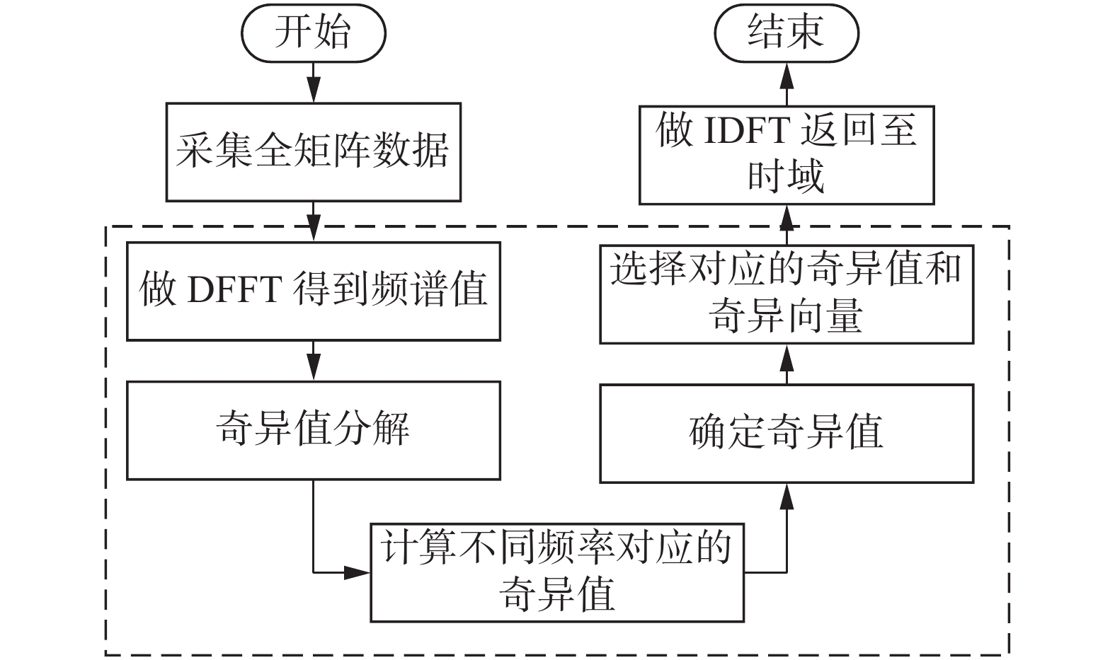
时间反转算子分解法是一种基于多维数据的信号处理方法.图3给出了基于时间反转算子分解的超声阵列去噪方法的流程图.首先利用超声阵列获得的全矩阵数据,构造时间反转算子.之后对其进行奇异值分解,并从中提取出非零奇异向量构造信号子空间.最后利用信号子空间产生重构全矩阵数据,实现全矩阵数据的降噪处理.
![]() 图 3 基于时间反转算子分解的全聚焦成像方法的流程图Figure 3. Flow chart of total focus imaging method based on DORT
图 3 基于时间反转算子分解的全聚焦成像方法的流程图Figure 3. Flow chart of total focus imaging method based on DORT对采集的全矩阵数据进行傅里叶变换,得到频域矩阵
$ {\boldsymbol{K}}(f) $ ,其中$ {k_{ij}}(f) = {[{\boldsymbol{K}}(f)]_{ij}} $ ,i ,j = 1,2,···,N.$ {k_{ij}}(f) $ 为第i个阵元激励第j个阵元接收的频域信号.因此该频域矩阵既包含了频域信息,又包含了传感器及散射体间的位置关系.利用该频域矩阵可生成时间反转算子[21-22],即$$ {\boldsymbol{T}}(f) = {{\boldsymbol{K}}^*}(f){\boldsymbol{K}}(f) $$ (9) 式中:
$ * $ 表示共轭转置.频域中取共轭相当于时域中进行了时间反转.上式给出了全矩阵数据时间反转处理的基本原理.对频域矩阵
${\boldsymbol{K}}(f)$ 进行奇异值分解,即$$ \boldsymbol{K}(f)=\boldsymbol{U}(f) \boldsymbol{\varSigma}(f) \boldsymbol{V}^{*}(f) $$ (10) 式中:
$ {\boldsymbol{U}}(f) $ 表示左奇异向量组成的酉矩阵;$ {{\boldsymbol{V}}^*}(f) $ 表示右奇异向量组成的酉矩阵;${\boldsymbol{\varSigma }}(f)$ 表示奇异值构成的实对角阵.将式(10)代入式(9)得$$ \begin{split} & {\boldsymbol{T}}(f) = {{\boldsymbol{K}}^*}(f){\boldsymbol{K}}(f) = {\left( {{\boldsymbol{U}}(f){\boldsymbol{\varSigma }}(f){{\boldsymbol{V}}^*}(f)} \right)^*}{\boldsymbol{U}}(f){\boldsymbol{\varSigma }}(f){{\boldsymbol{V}}^*}(f) = \hfill \\ &{\boldsymbol{V}}(f){{\boldsymbol{\varSigma }}^*}(f){{\boldsymbol{U}}^*}(f){\boldsymbol{U}}(f){\boldsymbol{\varSigma }}(f){{\boldsymbol{V}}^*}(f) = {\boldsymbol{V}}(f){{\boldsymbol{\varSigma }}^2}(f){{\boldsymbol{V}}^*}(f) \end{split} $$ (11) 将式(11)两端同时右乘矩阵
$ {\boldsymbol{V}}(f) $ ,得到$$ {\boldsymbol{T}}(f){\boldsymbol{V}}(f) = {\boldsymbol{V}}(f){{\boldsymbol{\varSigma }}^2}(f) $$ (12) 式(12)为时间反转算子的特征分解形式.对比式(12)和式(10)可以看出,时间反转算子
$ {\boldsymbol{T}}(f) $ 的奇异值是频域矩阵$ {\boldsymbol{K}}(f) $ 的奇异值的平方,$ {\boldsymbol{T}}(f) $ 的特征向量矩阵对应$ {\boldsymbol{K}}(f) $ 的奇异向量矩阵.为提高信号处理的效率,可以直接对频域矩阵$ {\boldsymbol{K}}(f) $ 进行奇异值分解.对于阵列获取的全矩阵数据,其奇异值的大小反映了反射波能量的强弱.若设定的阈值为
$ {\lambda _{{ts}}}(f) $ ,将满足$\lambda _1^2(f) > \cdots > \lambda _{{M_s}}^2(f) \geqslant \lambda _{ts}^2(f)$ 条件对应的列向量构成信号子空间{$ {v_1}(f), \cdots ,{v_{{M_s}}}(f) $ };相反,将满足${\lambda _{ts}}(f) > {\lambda _{{M_s} + 1}}(f) > \cdots > {\lambda _N}(f) \approx 0$ 条件对应的列向量构成噪声子空间{$ {v_{{M_s} + 1}}(f), \cdots ,{v_N}(f) $ }.即将较大奇异值对应的奇异向量构成信号子空间,将较小奇异值对应的奇异向量构成噪声子空间.该过程可表示为$$ \begin{split}{\boldsymbol{K}}(f) &={\sigma }_{p(f)}(f){{\boldsymbol{u}}}_{p(f)}(f){{\boldsymbol{v}}}_{p(f)}{}^{*}(f)+ \\ & {\displaystyle \sum _{q¹p(f)}^{N}{\sigma }_{q}}(f){{\boldsymbol{u}}}_{q}(f){{\boldsymbol{v}}}_{q}{}^{*}(f)\end{split}$$ (13) 式中:
$p(f) $ 表示不同频率下信号对应的奇异值数量,$ \sigma $ 表示特征值;u和v*表示特征值对应的奇异向量;$ q$ 表示不同频率下噪声对应的奇异值数量.根据奇异值大小,上式将信号分为有用信号子空间和噪声子空间,揭示了基于时间反转算子方法的降噪原理.对于实际超声检测信号,与缺陷相关的奇异值并非集中在单一频率处,而是在频域上具有一定分布性.对于单一模式的体波检测,声波从各阵元传播到缺陷的时间延迟是不随频率的变化而变化的.因此可以利用其它频率下各阵元的延迟时间相对中心频率下各阵元的延迟时间取极大值时,对应的奇异值作为该频率下的奇异值数量
$ p(f) $ .对中心频率$ {f_c} $ 下对应的奇异值向量${{\boldsymbol{v}}_{{\text{ref}}}} = {{\boldsymbol{v}}_1}({f_c})$ 进行相位解缠,得到中心频率下各阵元到达缺陷处的延迟时间$ {{\mathbf{\tau }}_{{\text{ref}}}} $ 为$$ {\tau _{{\rm{ref}}}} = \frac{{\max [\arg ({v_{{\rm{ref}}}})] - \arg ({v_{{\rm{ref}}}})}}{{2{\text{π}} {f_c}}} $$ (14) 以中心频率下对应的时延
${{\boldsymbol{\tau }}_{{\text{ref}}}}$ 作为参考,将其它频率下时延${{\boldsymbol{\tau }}_q}(f)$ 与${{\boldsymbol{\tau }}_{{\text{ref}}}}$ 进行互相关分析,将不同频率下相关分析的最大值的所对应的索引值作为该频率下的奇异值数量,即$$ p(f) = \mathop {\arg \max }\limits_{1 \leqslant q \leqslant N} \left( {\frac{{{{\boldsymbol{\tau }}_q}^ * (f){{\boldsymbol{\tau }}_{{\text{ref}}}}}}{{\left\| {{{\boldsymbol{\tau }}_q}(f)} \right\|\left\| {{{\boldsymbol{\tau }}_{{\text{ref}}}}} \right\|}}} \right) $$ (15) 式中:
$\left\| {\,} \right\|$ 表示求取范数.根据上式可以确定的不同频率下奇异值的数量,可以确定式(13)中的信号子空间,从而可以得到去噪处理后的频域数据矩阵,即$$ {\boldsymbol{\hat K'}}(f) = {\sigma _p}(f){{\boldsymbol{u}}_p}(f){{\boldsymbol{v}}_{p(f)}}^ * (f) $$ (16) 式(16)为去噪后的频域矩阵,对其进行反傅里叶变换可以得到降噪后的全矩阵数据.
2. 各向异性焊缝中超声传播数值仿真
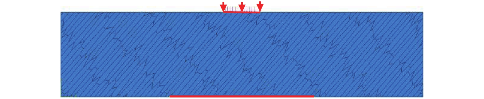
基于ABAQUS有限元仿真平台,利用Voronoi图建立柱状晶结构有限元模型,如图4所示.模型大小为50 mm × 10 mm,材料为316不锈钢,参数如表1所示.激励信号采用中心频率为5 MHz的3周期汉宁窗调制信号.
表 1 材料属性表Table 1. Table of Material property密度
ρ/(kg·m−3)声张量
C11/GPa声张量
C12/GPa声张量
C23/GPa声张量
C33/GPa声张量
C66/GPa各向异性系数
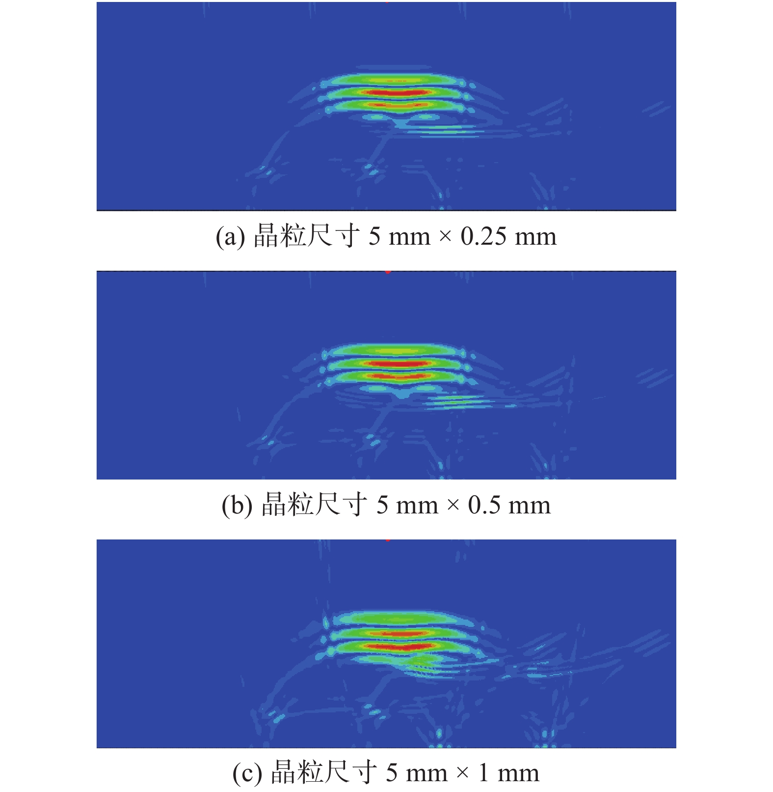
r8 010 216 145 98 263 129 1.925 在不同晶粒尺寸和取向下,对柱状晶介质中超声波传播进行了数值仿真.图5给出晶粒方向为45°,几种典型晶粒度尺寸模型中超声波传播到3 μs时得到的同一标准显示下的仿真云图.可以看出,超声波在柱状晶介质中传播时,出现了明显的散射噪声,且散射噪声随着晶粒尺寸增大而增加.
![]() 图 5 超声波在不同晶粒大小模型中传播位移云图Figure 5. Displacement nephogram under different grain size. (a) grain size 5 mm × 0.25 mm; (b) grain size 5 mm × 0.5 mm; (c) grain size 5 mm × 1 mm
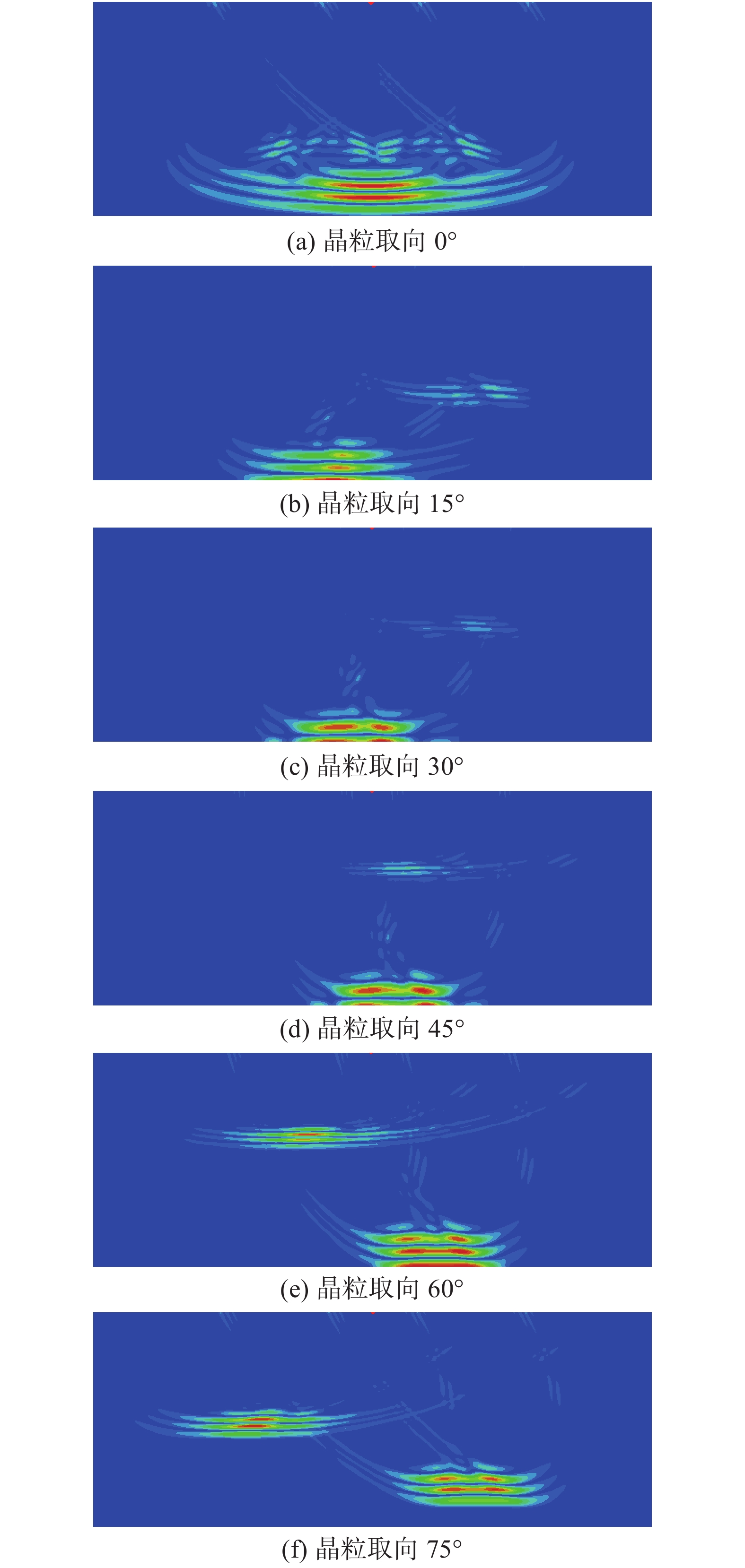
图 5 超声波在不同晶粒大小模型中传播位移云图Figure 5. Displacement nephogram under different grain size. (a) grain size 5 mm × 0.25 mm; (b) grain size 5 mm × 0.5 mm; (c) grain size 5 mm × 1 mm图6给出了晶粒尺寸为5 mm × 0.5 mm,几种典型晶粒取向模型中超声波传播到2 μs时得到的仿真云图.对比位移云图可以看出,晶粒取向对超声波的传播方向及模式转换有很大的影响.具体表现为:不同晶粒取向下超声波的偏折方向及模式转换产生的横波强度的变化.
![]() 图 6 不同晶粒取向下的位移云图Figure 6. Displacement nephogram under different grain orientation. (a) grain orientation is 0°; (b) grain orientation is 15°; (c) grain orientation is 30; (d) grain orientation is 45°; (e) grain orientation is 60°; (f) grain orientation is 75°
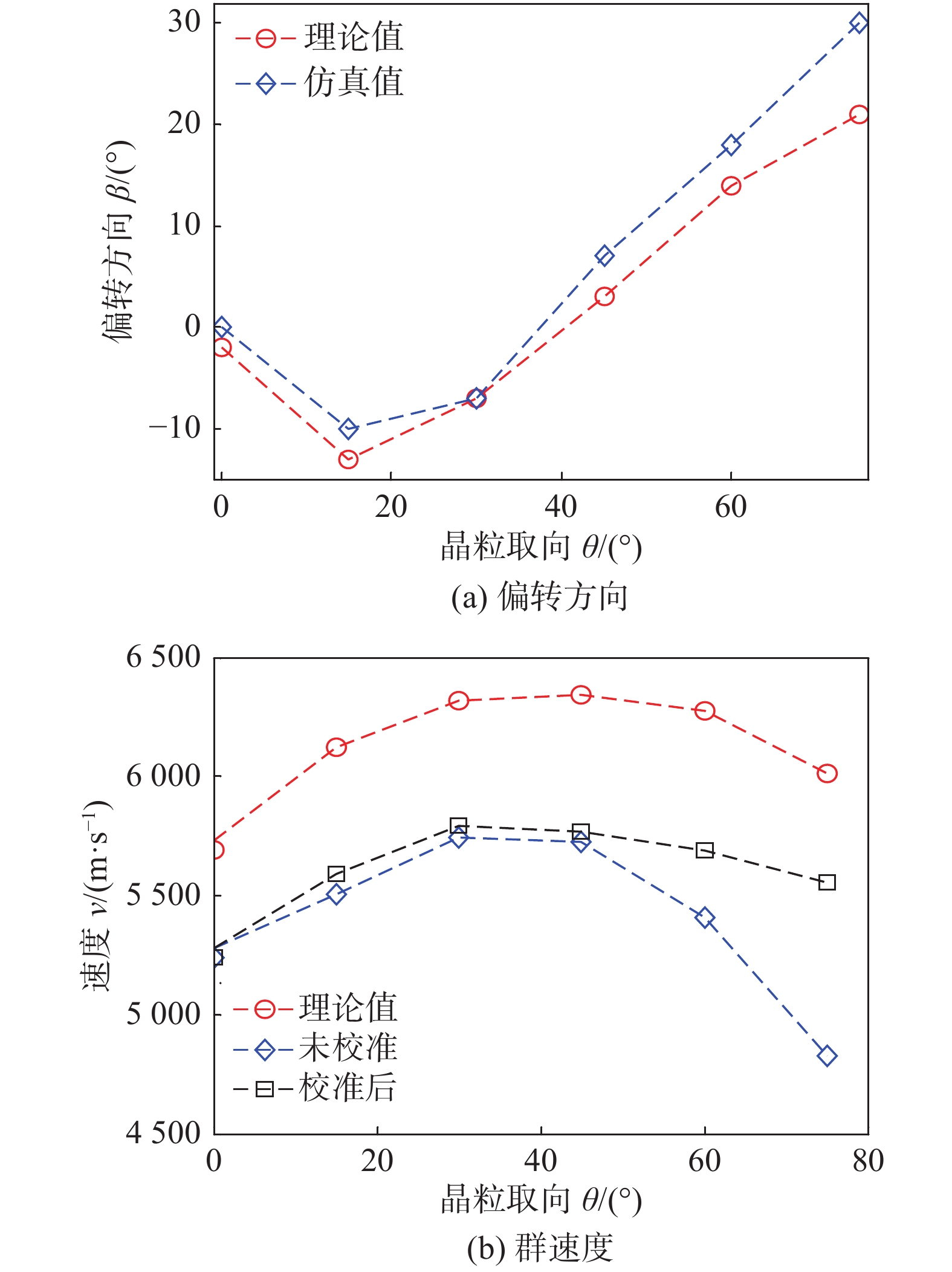
图 6 不同晶粒取向下的位移云图Figure 6. Displacement nephogram under different grain orientation. (a) grain orientation is 0°; (b) grain orientation is 15°; (c) grain orientation is 30; (d) grain orientation is 45°; (e) grain orientation is 60°; (f) grain orientation is 75°图7给出了不同晶粒取向下超声波的偏转方向和群速度.其中偏转方向指超声波的传播方向与入射方向的夹角.逆时针为负,顺时针为正.由图7a可以看出,数值仿真得到的超声波偏转方向与根据Christoffel方程计算得到的理论值吻合较好.图7b给出了不同晶粒取向下的纵波波速.其中未校准是指假设超声波沿直线传播计算得到的群速度,校准后指考虑了超声波的偏折传播得到的群速度,理论值指根据Christoffel方程推导出的波速值.可以看出,考虑偏折后得到的不同晶粒取向下的群速度与理论群速度变化规律一致,但由于理论模型与数值仿真模型参数的差异,使得二者数值上存在一定偏差.因此,超声波在柱状晶介质中传播时,在固定的入射方向下,超声波的传播方向和速度大小与晶粒的取向有关.
![]() 图 7 不同晶粒取向下超声波的偏转方向和群速度Figure 7. Deflection direction and group velocity of different grain orientation at different positions. (a) deflection direction; (b) group velocity
图 7 不同晶粒取向下超声波的偏转方向和群速度Figure 7. Deflection direction and group velocity of different grain orientation at different positions. (a) deflection direction; (b) group velocity数值仿真结果说明,超声波在柱状晶介质中传播时,不仅会产生散射噪声,其声束传播方向会发生偏折,其传播速度与入射声波与晶粒方向的相对方向有关.
3. 各向异性焊缝超声阵列检测试验
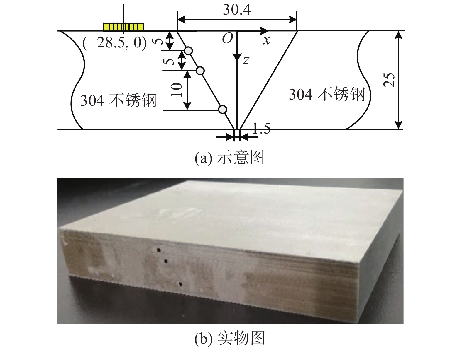
开展了304奥氏体不锈钢焊缝缺陷超声阵列检测试验.图8给出了待测试件的结构及实物图.图中“O”表示坐标原点,位于焊缝区顶部中间点的位置.在焊缝与母材的交接处加工了3个直径为2 mm的圆孔缺,其位置坐标分别为(−12.3, 5),(−9.4, 10)和(−3.6, 20).相控阵探头位于(−28.5, 0)位置处.
![]() 图 8 待测试件截面图及实物图 (mm)Figure 8. Cross-sectional drawing and physical drawing of the tested sample. (a) cross-sectional drawing; (b) physical drawing
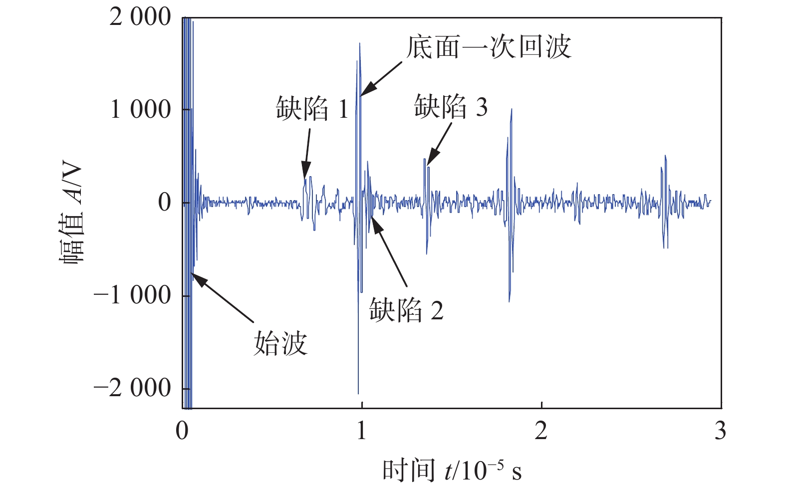
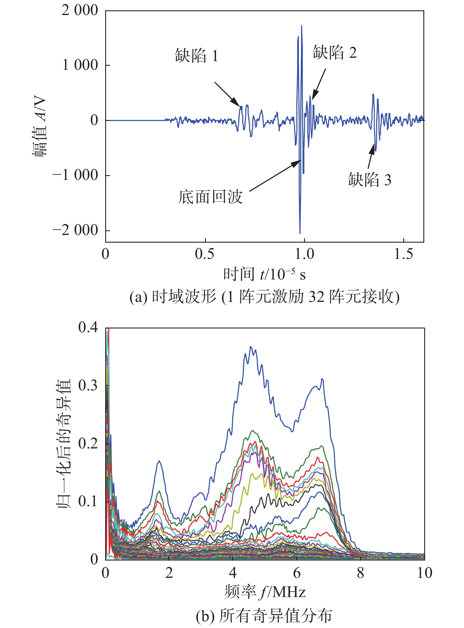
图 8 待测试件截面图及实物图 (mm)Figure 8. Cross-sectional drawing and physical drawing of the tested sample. (a) cross-sectional drawing; (b) physical drawing试验系统包括计算机、相控阵系统(MULTI2000)及5 MHz商用相控阵探头.相控阵探头阵元数量为32,阵元宽度为0.5 mm,阵元间距为0.6 mm. 激励信号采用中心频率为5 MHz的5周期的汉宁窗调制的正弦脉冲信号,采样频率为100 MHz.相控阵检测模式为全矩阵数据采集模式.采集到的全矩阵数据中,1阵元自激自收的时域信号如图9所示. 从图中可知,可以从时域信号清晰的看出始波、底面一次回波和3个缺陷回波信号,但是缺陷信号幅值较小.
![]() 图 9 第1阵元激励第32阵元接收到的时域信号Figure 9. Signal received by the thirty-second element and excited by first element
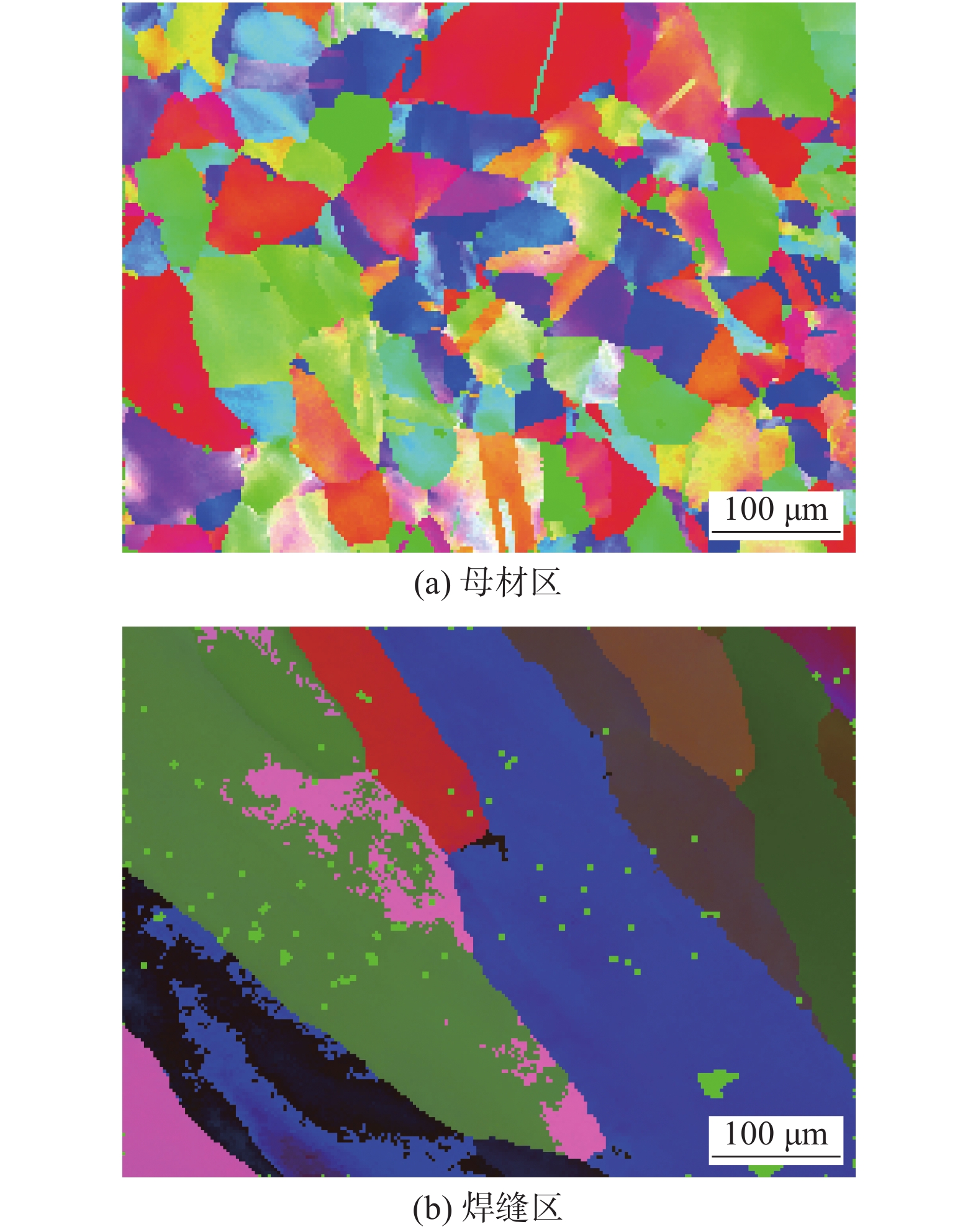
图 9 第1阵元激励第32阵元接收到的时域信号Figure 9. Signal received by the thirty-second element and excited by first element根据上述数值仿真可知,超声波在多晶介质中传播波速与介质的微观结构及超声波的入射方向有关.图10给出了利用电子背散射衍射(electron backscattered diffraction,EBSD)技术对焊缝区及母材区进行微观观测的典型结果.可以看出,母材区为等轴晶,焊缝区为柱状晶.与仿真模型一致.
![]() 图 10 微观观测结果Figure 10. Microscopic observation results using EBSD. (a) parent metal area; (b) weld area
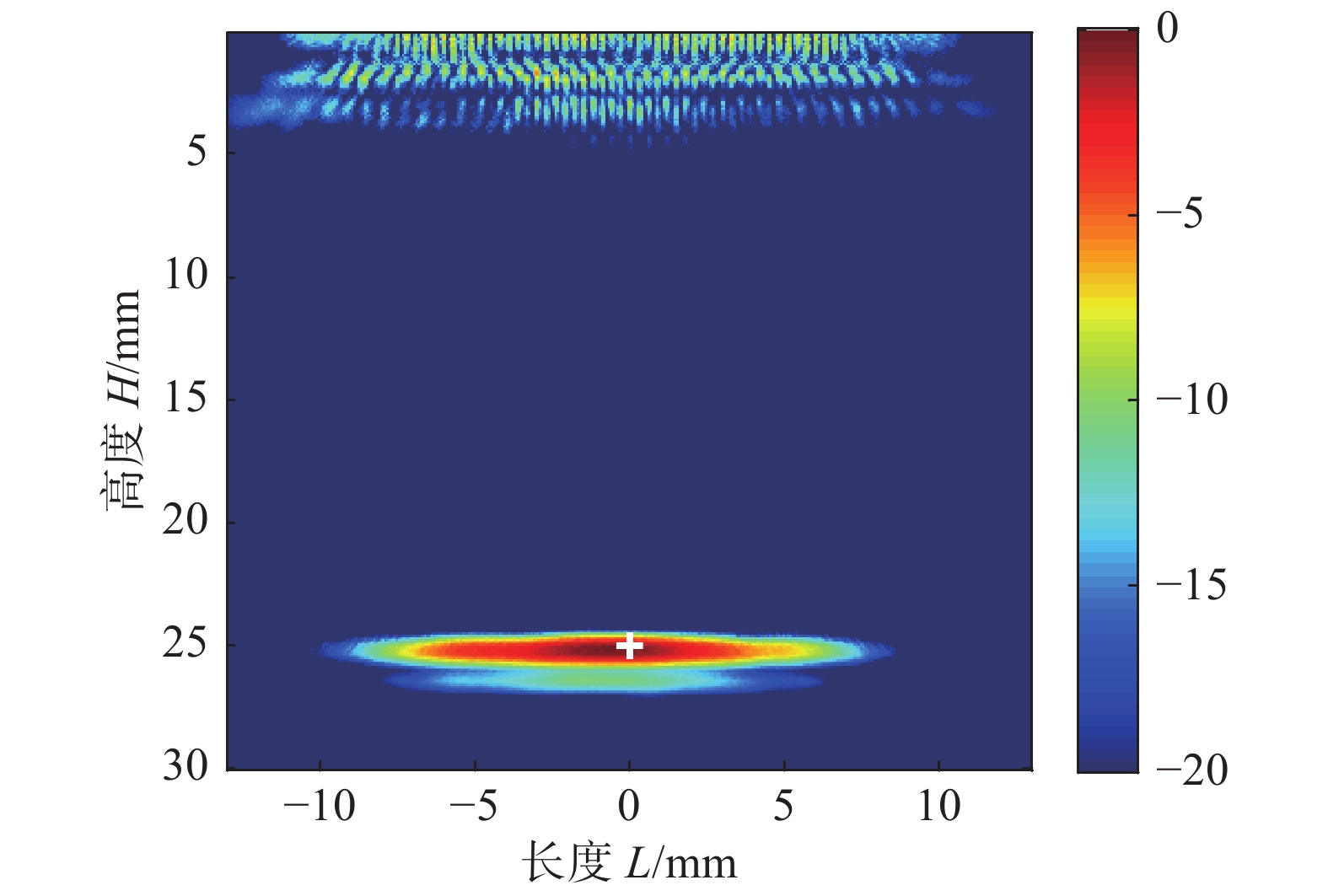
图 10 微观观测结果Figure 10. Microscopic observation results using EBSD. (a) parent metal area; (b) weld area超声波在等轴晶材料中传播时,入射方向不同,速度大小不同.为了确定速度的差异性,首先对采集的全矩阵数据对阵列下方区域进行成像.传感器的位置与图8所示的位置一致,通过计算的超声波的速度为5 400 m/s,使用此速度值进行全聚焦成像,成像结果如图11所示.图中的颜色表示成像幅值取对数后的dB值,0表示当前位置处的幅值最大,−20 dB表示当前位置处的幅值较小. 可以看出,纵波成像结果与实际的底面相吻合.
![]() 图 11 母材区全聚焦成像结果Figure 11. Imaging result of masterbatch zone using total focus method
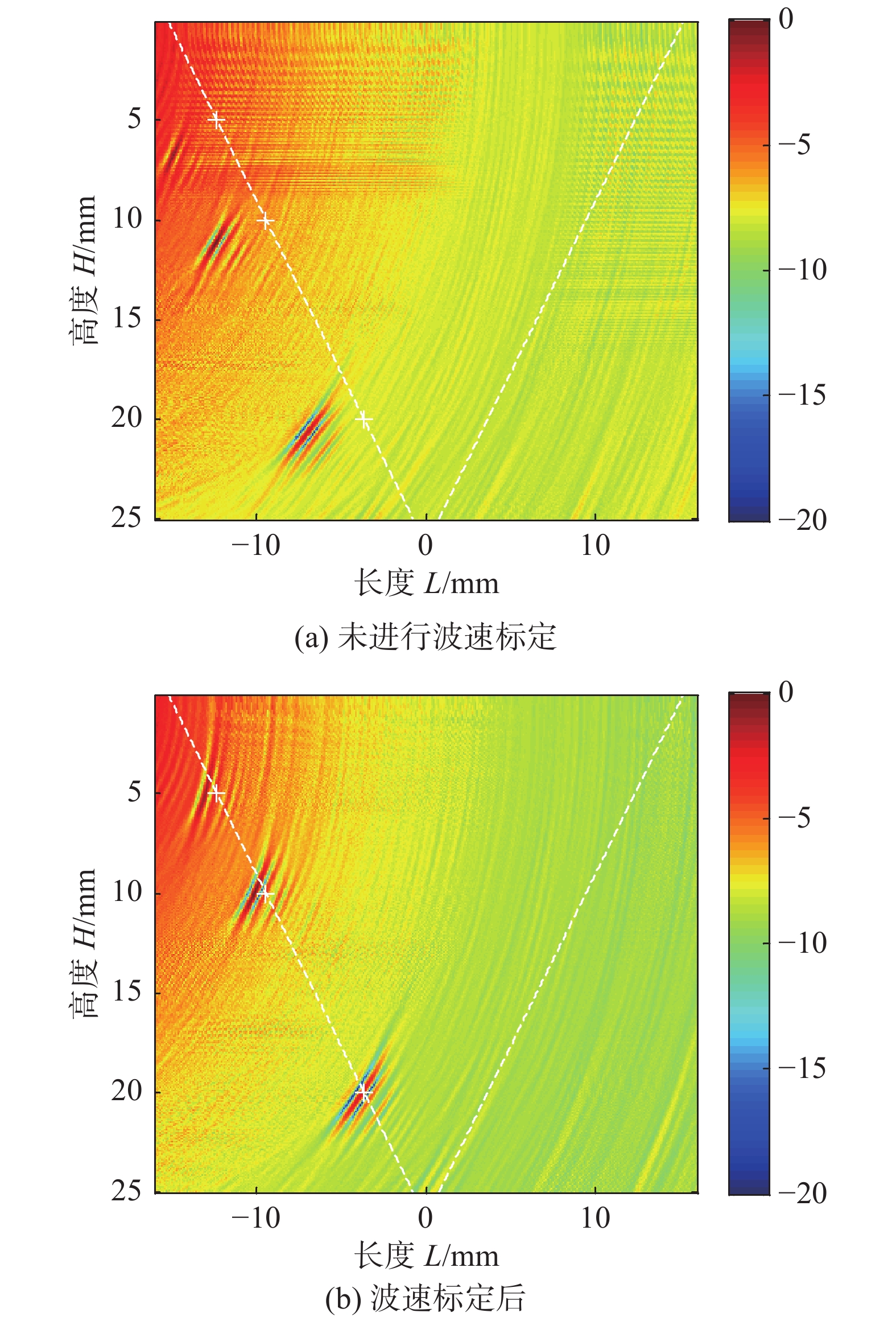
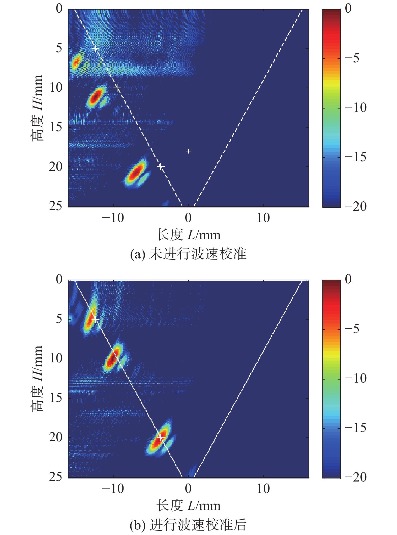
图 11 母材区全聚焦成像结果Figure 11. Imaging result of masterbatch zone using total focus method利用采集的全矩阵数据对焊缝区域成像,按照速度值5 400 m/s得到的成像结果如图12a所示. 图中“ + ”为缺陷的实际位置.图中的颜色表示成像幅值取对数后的dB值,0表示当前位置处的幅值最大,−20 dB表示当前位置处的幅值较小. 文中其它全聚焦成像图的含义与此同,后续不再一一赘述. 可以看出,全聚焦成像中得到的缺陷位置与缺陷的实际位置有一定的偏差.对焊缝区的波速进行测量,利用校正后的速度5 750 m/s,并考虑声线的偏折,利用改进的全聚焦得到的成像结果如图12b所示.可以看出,3个缺陷均呈现在焊缝区与母材区的交界线上,成像中得到的缺陷位置与实际缺陷的位置相符.缺陷2和缺陷3位置处的成像幅值较大,而靠近试件上端面的缺陷1的成像幅值较小.
![]() 图 12 焊缝区全聚焦成像结果Figure 12. Total focus imaging result of weld zone. (a) without velocity calibration; (b) with velocity calibration
图 12 焊缝区全聚焦成像结果Figure 12. Total focus imaging result of weld zone. (a) without velocity calibration; (b) with velocity calibration为进一步比较两种成像方法的缺陷定位,表2给出了两种成像方法得到的缺陷位置及与对应缺陷的实际位置的距离差
$\Delta L$ .分析可知,利用常规全聚焦成像方法得到的3个缺陷位置与缺陷实际位置的误差约为3 mm.速度校准后,利用改进的全聚焦成像得到的缺陷位置与其实际位置的误差约为0.5 mm. 因此改进的全聚焦成像方法提高了缺陷定位的准确性.表 2 缺陷定位结果Table 2. Results of defect location缺陷编号 缺陷位置
坐标(mm)常规方法定
位坐标 (mm)距离
$\Delta L_1$ /mm校正方法定
位坐标(mm)距离
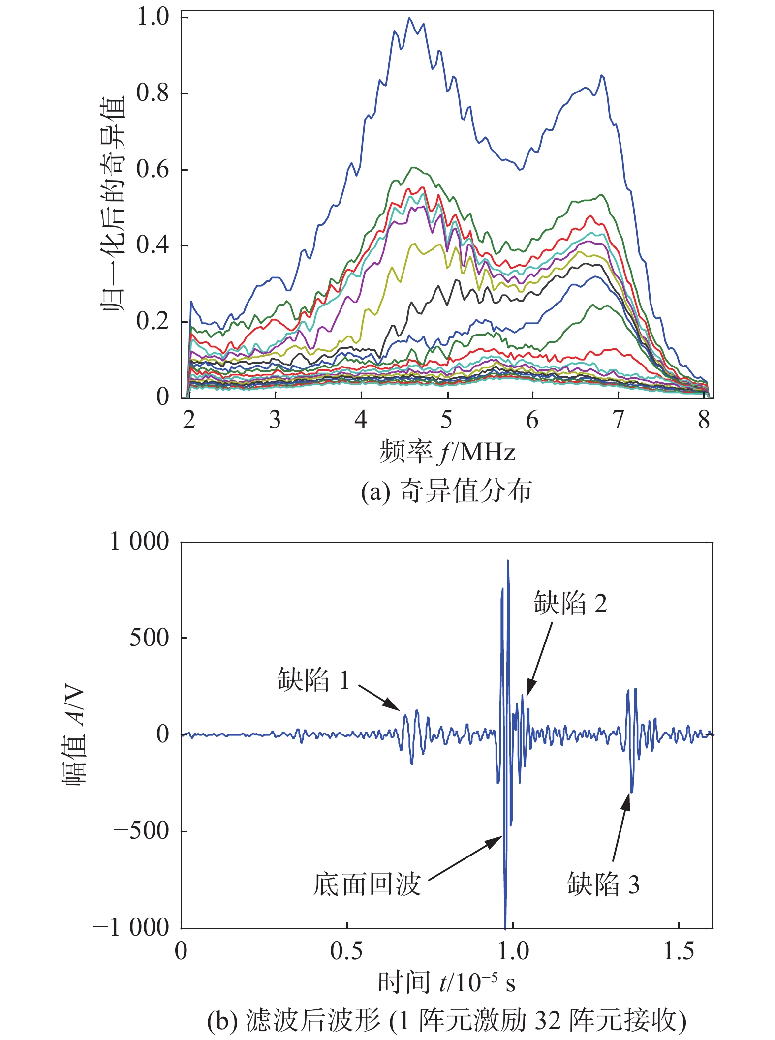
$\Delta L_2$ /mm1 (−12.3,5) (−14.5,6.85) 2.89 (−12.63,5.4) 0.52 2 (−9.4,10) (−12.08, 11.3) 2.97 (−9.78,10.35) 0.51 3 (−3.6,20) (−6.83,20.95) 3.36 (−3.48,20.25) 0.28 基于波束偏折的全聚焦成像方法很好实现了缺陷的定位,但其成像的信噪比较低,图12中的成像结果的信噪比分别为8.48和7.65 dB.针对焊缝全聚焦成像结果信噪比低问题,将基于时间反转算子分解方法应用于全矩阵数据处理,处理的范围为3 ~ 16 μs的时间窗内.图13a给出了图9所示信号进行时间反转前加窗后波形.在该时间窗范围内,可以分辨出信号中包含的3个缺陷回波及底面回波.对该时间窗内的全矩阵数据进行处理后得到的所有奇异值分布如图13b所示.
![]() 图 13 典型时域信号及全矩阵数据的奇异值分布Figure 13. Typical waveform and singular value distribution of full matrix data. (a) time domain signal (element 1 excites element 32 to receive); (b) all singular value distributions
图 13 典型时域信号及全矩阵数据的奇异值分布Figure 13. Typical waveform and singular value distribution of full matrix data. (a) time domain signal (element 1 excites element 32 to receive); (b) all singular value distributions依据中心频率下对应的奇异值的数量,作为选取的奇异值的数量.图14a给出了按照中心频率下奇异值数量选出的奇异值分布,图14b为滤波后的时域信号.可以看出,滤波后的时域信号的幅值比滤波前略有减小,但信噪比有所提高.
![]() 图 14 选出的奇异值分布及滤波后的时域信号Figure 14. Selected singular value distribution and waveform after filtering. (a) singular value distributions; (b) time domain signal after noise reduction (element 1 excites element 32 to receive)
图 14 选出的奇异值分布及滤波后的时域信号Figure 14. Selected singular value distribution and waveform after filtering. (a) singular value distributions; (b) time domain signal after noise reduction (element 1 excites element 32 to receive)图15给出了经时间反转算子预处理后全矩阵数据的全聚焦成像结果.其中图15a为传统全聚焦成像结果,图15b为经波速校准后的全聚焦成像结果.与图12相比,两种成像结果的噪声明显减少,成像信噪比均有显著高.其中,图15a成像的信噪比提高了14.51 dB.图15b成像的信噪比提高了17.08 dB.
![]() 图 15 经时间反转算子处理后的全聚焦成像结果Figure 15. Total focus imaging result of weld zone after processed by DORT. (a) without velocity calibration; (b) with velocity calibration
图 15 经时间反转算子处理后的全聚焦成像结果Figure 15. Total focus imaging result of weld zone after processed by DORT. (a) without velocity calibration; (b) with velocity calibration综上可知,对于奥氏体不锈钢焊缝中的缺陷检测,与常规的全聚焦成像结果相比,经时间反转算子预处理和波速校正后的全聚焦成像结果的信噪比更高,定位偏差更小.因此基于时间反转算子降噪和射线追踪的波速校正的全聚焦成像方法可以有效用于奥氏体不锈钢焊缝中缺陷检测.
4. 结论
(1) 利用射线追踪法,研究了各向异性介质中超声波传播路径确定方法,并将其应用于奥氏体不锈钢焊缝超声阵列全聚焦成像的声束偏折校正,提高了超声阵列全聚焦成像中缺陷定位的精度.
(2) 发展了一种基于时间反转算子分解的超声阵列信号去噪方法,很好剔除了奥氏体不锈钢焊缝检测信号中的散射噪声,凸显了特征回波信息,可将全聚焦成像的信噪比提高10 dB以上.
-
![]()
图 3 基于时间反转算子分解的全聚焦成像方法的流程图
Figure 3. Flow chart of total focus imaging method based on DORT
![]()
图 5 超声波在不同晶粒大小模型中传播位移云图
Figure 5. Displacement nephogram under different grain size. (a) grain size 5 mm × 0.25 mm; (b) grain size 5 mm × 0.5 mm; (c) grain size 5 mm × 1 mm
![]()
图 6 不同晶粒取向下的位移云图
Figure 6. Displacement nephogram under different grain orientation. (a) grain orientation is 0°; (b) grain orientation is 15°; (c) grain orientation is 30; (d) grain orientation is 45°; (e) grain orientation is 60°; (f) grain orientation is 75°
![]()
图 7 不同晶粒取向下超声波的偏转方向和群速度
Figure 7. Deflection direction and group velocity of different grain orientation at different positions. (a) deflection direction; (b) group velocity
![]()
图 8 待测试件截面图及实物图 (mm)
Figure 8. Cross-sectional drawing and physical drawing of the tested sample. (a) cross-sectional drawing; (b) physical drawing
![]()
图 9 第1阵元激励第32阵元接收到的时域信号
Figure 9. Signal received by the thirty-second element and excited by first element
![]()
图 10 微观观测结果
Figure 10. Microscopic observation results using EBSD. (a) parent metal area; (b) weld area
![]()
图 11 母材区全聚焦成像结果
Figure 11. Imaging result of masterbatch zone using total focus method
![]()
图 12 焊缝区全聚焦成像结果
Figure 12. Total focus imaging result of weld zone. (a) without velocity calibration; (b) with velocity calibration
![]()
图 13 典型时域信号及全矩阵数据的奇异值分布
Figure 13. Typical waveform and singular value distribution of full matrix data. (a) time domain signal (element 1 excites element 32 to receive); (b) all singular value distributions
![]()
图 14 选出的奇异值分布及滤波后的时域信号
Figure 14. Selected singular value distribution and waveform after filtering. (a) singular value distributions; (b) time domain signal after noise reduction (element 1 excites element 32 to receive)
![]()
图 15 经时间反转算子处理后的全聚焦成像结果
Figure 15. Total focus imaging result of weld zone after processed by DORT. (a) without velocity calibration; (b) with velocity calibration
表 1 材料属性表
Table 1 Table of Material property
密度
ρ/(kg·m−3)声张量
C11/GPa声张量
C12/GPa声张量
C23/GPa声张量
C33/GPa声张量
C66/GPa各向异性系数
r8 010 216 145 98 263 129 1.925  下载: 导出CSV
表 2 缺陷定位结果
Table 2 Results of defect location
缺陷编号 缺陷位置
坐标(mm)常规方法定
位坐标 (mm)距离 $\Delta L_1$ /mm校正方法定
位坐标(mm)距离 $\Delta L_2$ /mm1 (−12.3,5) (−14.5,6.85) 2.89 (−12.63,5.4) 0.52 2 (−9.4,10) (−12.08, 11.3) 2.97 (−9.78,10.35) 0.51 3 (−3.6,20) (−6.83,20.95) 3.36 (−3.48,20.25) 0.28
下载: 导出CSV
-
[1] Chai F, Yan F, Wang W, et al. Microstructures and mechanical properties of AZ91 alloys prepared by multi-pass friction stir processing[J]. Journal of Materials Research, 2018, 33(12): 1789 − 1796. doi: 10.1557/jmr.2018.98
[2] Xue P, Zhang X X, Wu L H, et al. Research progress on friction stir welding and processing[J]. Acta Metallurgica Sinica, 2016, 52(10): 1222 − 1238.
[3] 黎桂江, 彭倩, 李聪, 等. 316L奥氏体不锈钢QPQ盐浴复合处理后的显微组织分析[J]. 金属热处理, 2007(10): 23 − 25. doi: 10.3969/j.issn.0254-6051.2007.10.006 Li Guijiang, Peng Qian, Li Cong, et al. Microstrueture analysis for 316L austenitic stainless steel after QPQ complex salt bath heat treatment[J]. Heat Treatment of Metals, 2007(10): 23 − 25. doi: 10.3969/j.issn.0254-6051.2007.10.006
[4] 颜泽钢, 王克鸿. 高氮奥氏体不锈钢Cr22Mn18NiN MIG焊接接头组织性能研究[J]. 机械制造与自动化, 2017, 46(5): 45 − 47. Yan Zegang, Wang Kehong. Researching on microstructural properties of HNS Cr22Mn18NiN welded joints[J]. Machine Building &Automation, 2017, 46(5): 45 − 47.
[5] Taheri H, Kilpatrick M, Norvalls M, et al. Investigation of nondestructive testing methods for friction stir welding[J]. Metals-Open Access Metallurgy Journal, 2019, 9(6): 1 − 12.
[6] Li W, Zhou Z, Li Y. Inspection of butt welds for complex surface parts using ultrasonic phased array[J]. Ultrasonics, 2019, 96: 75 − 82. doi: 10.1016/j.ultras.2019.02.011
[7] Liu Q, Wirdelius H. A 2D model of ultrasonic wave propagation in an anisotropic weld[J]. NDT & E International, 2007, 40(3): 229 − 238.
[8] 胡宏伟, 王泽湘, 彭凌兴, 等. 基于均方根速度的水浸超声合成孔径聚焦成像[J]. 仪器仪表学报, 2016, 37(2): 365 − 370. Hu Hongwei, Wang Zexiang, Peng Lingxing, et al. Immersion ultrasonic imaging using the synthetic aperture focusing technique based on the root mean square velocity[J]. Chinese Journal of Scientific Instrument, 2016, 37(2): 365 − 370.
[9] Ogilvy J A. Ultrasonic beam profiles and beam propagation in an austenitic weld using a theoretical ray tracing model[J]. Ultrasonics, 1986, 24(6): 337 − 347. doi: 10.1016/0041-624X(86)90005-3
[10] Schmitz V, Walte F, Chakhlov S V. 3D ray tracing in austenite materials[J]. NDT & E International, 1999, 32(4): 201 − 213.
[11] 杨敬, 吴斌, 焦敬品, 等. 各向异性焊缝缺陷超声阵列全聚焦成像方法[J]. 声学学报, 2019, 44(1): 125 − 135. Yang Jing, Wu Bin, Jiao Jingpin, et al. Total focus imaging of defects in anisotropic welds using ultrasonic array[J]. Acta Acustica, 2019, 44(1): 125 − 135.
[12] Zhang J, Hunter A, Drinkwater B W, et al. Monte carlo inversion of ultrasonic array data to map anisotropic weld properties[J]. IEEE Transactions on Ultrasonics Ferroelectrics and Frequency Control, 2012, 59(11): 2487 − 2497. doi: 10.1109/TUFFC.2012.2481
[13] Ye J, Kim H J, Song S J, et al. Model-based simulation of focused beam fields produced by a phased array ultrasonic transducer in dissimilar metal welds[J]. NDT & E International, 2011, 44(3): 290 − 296.
[14] Nowers O, Duxbury D J, Zhang J, et al. Novel ray-tracing algorithms in NDE: Application of Dijkstra and A* algorithms to the inspection of an anisotropic weld[J]. NDT & E International, 2014, 61: 58 − 66.
[15] 陈果, 孙颖, 陈文生, 等. HHT在粗晶材料超声检测中的应用[J]. 失效分析与预防, 2013, 8(3): 141 − 144. Chen Guo, Sun Ying, Chen Wensheng, et al. Application of HHT in ultrasonic testing of coarse grain materials[J]. Failure Analysis and Prevention, 2013, 8(3): 141 − 144.
[16] 陈建忠, 史淑, 史耀武. 小波变换的原理及其在噪声材料超声评价中的应用[J]. 宇航材料工艺, 1999(3): 29 − 35. Chen Jianzhong, Shi Shu, Shi Yaowu. Use of wavelet transform in ultrasonic evaluation of noisy materials[J]. Aerospace Materials & Technology, 1999(3): 29 − 35.
[17] Praveen A, Vijayarekha K, Abraham S T, et al. Signal quality enhancement using higher order wavelets for ultrasonic TOFD signals from austenitic stainless steel welds[J]. Ultrasonics, 2013, 53(7): 1288 − 1292. doi: 10.1016/j.ultras.2013.03.013
[18] Yavuz M E, Teixeira F L. Full time-domain DORT for ultrawideband electromagnetic fields in dispersive, random inhomogeneous media[J]. IEEE Transactions on Antennas and Propagation, 2006, 54(8): 2305 − 2315. doi: 10.1109/TAP.2006.879196
[19] Mathias F. Time reversal of ultrasonic fields -part I: basic principles[J]. IEEE Transaction on Ultrasonics, Ferroelectrivs, and Frequency Control, 1992, 39(5): 555 − 566. doi: 10.1109/58.156174
[20] Deng F, Teixeira F L. Locating small structural damages in pipes using space-frequency DORT processing[J]. Results in Physics, 2017(7): 1637 − 1643.
[21] 邓菲, 胡方朝, 张僖. 基于时间反转算子分解算法的板中导波小缺陷成像[J]. 北京工业大学学报, 2018(5): 743 − 748. Deng Fei, Hu Fangchao, Zhang Xi. Imaging small damages in plates using DORT processing[J]. Journal of Beijing University of Technology, 2018(5): 743 − 748.
[22] Villaverde E L, Robert S, Prada C. Ultrasonic imaging of defects in coarse-grained steels with the decomposition of the time reversal operator[J]. Journal of the Acoustical Society of America, 2016, 140(1): 541 − 550. doi: 10.1121/1.4958683
[23] Villaverde E L, Robert S, Prada C. Ultrasonic imaging in coarse-grained stainless steels by total focusing method[C]//AIP Conference Proceedings, 2016: 1 − 6.
[24] 肖琨. 奥氏体不锈钢深厚焊缝缺陷超声相控阵检测技术[D]. 杭州: 中国计量学院, 2014. Xiao Kun. The detection of deep weld defects of austenitic stainless steel based on ultrasonic phased arrays[D]. Hangzhou: China Jiliang University, 2014.
[25] Cunningham L J, Mulholland A J, Tant K M M, et al. The detection of flaws in austenitic welds using the decomposition of the time-reversal operator[J]. Proceedings of the Royal Society A:Mathematical Physical and Engineering Sciences, 2016, 472(2188): 20150500. doi: 10.1098/rspa.2015.0500
-
期刊类型引用(8)
1. 彭炎,严宇,王俊龙,杨会敏,刘伟达,徐喆,陈春林. 厚壁奥氏体不锈钢焊缝TRL面阵探头全聚焦成像检测的仿真与分析. 无损检测. 2025(05): 8-17 .  百度学术
百度学术
2. 刘桂刚. 奥氏体不锈钢小径管焊缝超声波相控阵检测技术应用及分析. 金属加工(热加工). 2024(06): 130-136 . 百度学术
3. 倪国胜,娄琳,高志萌. 316L钢氩弧焊焊接接头超声检测可行性试验研究. 设备管理与维修. 2024(16): 12-14 . 百度学术
4. 迟大钊,徐智贤,刘海春,李庆生,郭强,苏维刚,贾涛. 基于改进SIFT算法的超声图像拼接方法. 焊接学报. 2024(10): 1-7 . 本站查看
5. 吴剑强. 低压低功耗集成电路引线钎缝超声波检测方法研究. 焊接技术. 2023(04): 76-80+114 . 百度学术
6. 朱新杰,李永涛,邓明晰,姚森. 一种用于焊接结构多帧满秩成像检测的超声SH导波换能器. 焊接学报. 2023(04): 84-92+134 . 本站查看
7. 邓丽娟. 双晶面阵列探头辐射声场特性仿真与分析. 水利技术监督. 2023(06): 10-13 . 百度学术
8. 苏雨露. 基于深度重采样的奥氏体不锈钢焊缝超声TOFD检测技术研究. 自动化应用. 2023(17): 132-134 . 百度学术
其他类型引用(7)


计量
- 文章访问数: 485
- HTML全文浏览量: 70
- PDF下载量: 97
- 被引次数: 15
