
High-temperature wear resistance of Co-based cladding layers by ultra-high speed laser cladding on the surface of the cast-rolling roller sleeve
-
摘要: 为了提高铸轧辊辊套的使用寿命,采用超高速激光熔覆技术在32Cr3Mo1V铸轧辊辊套表面制备了钴基熔覆层.分析了熔覆层的表面形貌、显微组织及高温摩擦磨损性能,并与优选常规激光熔覆层进行了对比. 结果表明,优选的超高速以及常规激光熔覆层均表面平整,与基体结合良好,无明显裂纹、气孔等缺陷. 超高速激光熔覆层显微组织非常均匀细小,枝晶轴间距极小,很大程度上抑制了枝晶偏析的范围,使得熔覆层的元素分布更加均匀. 在700 ℃高温摩擦磨损试验中,超高速激光熔覆层产生的氧化物磨屑更小,更容易发生团聚效应,有利于釉质层的形成,熔覆层变形量更小,对釉质层进行了有效支撑,出现大面积具有减摩耐磨作用的釉质层,表现出优异的耐高温摩擦磨损性能.Abstract: In order to improve the service life of the cast-rolling roller sleeve, a Co-based cladding layer was prepared on the surface of the 32Cr3Mo1V cast-rolling roller sleeve using ultra-high-speed laser cladding technology. The surface morphology, microstructure, high-temperature friction and wear properties of the cladding layer were analyzed. And which was compared with that of the preferred conventional laser cladding layer. The results show that the preferred ultra-high-speed and conventional laser cladding layers all have a smooth surface and a good combination with the substrate without obvious cracks, pores and other defects. In contrast, the microstructure of the layer by ultra-high-speed laser cladding is very uniform and fine. And the dendrite axis spacing is extremely small, which largely suppresses the range of dendrite segregation. As a result, the more uniform distribution of element was obtained. During the process of 700 ℃ high temperature friction and wear test, the super oxide wear debris produced from the high-speed laser cladding layer is more smaller compared with that of conventional laser cladding layer. Therefore the agglomeration effect is more likely to occur, which is conducive to the formation of the enamel layer with anti-friction resistance. As the same time, the deformation of the layer by ultra-high-speed laser cladding is smaller, which has more effectively support for the enamel layer, consequently a large area enamel layer can be obtained. Thus the ultra-high-speed laser cladding layer exhibits excellent high-temperature friction and wear resistance.
-
0. 序言
Q355B低合金钢凭借其强度高、塑性和韧性好等特点,被广泛应用于桥梁、船舶、轨道列车转向架等关键结构[1]. 在这些结构中,主要承载结构部件均经焊接而成,并在服役过程中承受着复杂的载荷条件. 而焊接接头在交变载荷条件下往往发生疲劳失效,继而成为整个结构中最薄弱的环节[2]. 因此,评估焊接结构的疲劳寿命至关重要,而焊接接头的应力状态以及相应的裂纹扩展路径更是成为了学者们关注的焦点. 评估焊接接头疲劳寿命最常用的方法有名义应力法、结构应力法等,这些方法对焊根失效问题均存在一定的局限性,准确评估疲劳寿命困难较大. 这是由于当焊根处起裂失效时,根部存在严重的应力集中,裂纹的扩展路径为焊缝区,疲劳寿命主要为焊缝区裂纹的扩展寿命,且扩展角度不同,扩展寿命不同. 当焊根处的宏观裂纹被监测到时,剩余疲劳寿命往往已不足20%[3-4],因此,准确获得根部裂纹扩展角度是评估焊根失效疲劳寿命的关键,也是结构设计中最重要的环节.
针对以上问题,Wang等人[5]采用最大周向应力准则(MCS法)模拟裂纹扩展,即裂纹垂直于最大周向应力方向从裂纹尖端开始沿径向扩展,故可以将周向应力(σθθ)达到最大时的角度作为裂纹扩展的角度. 王苹等人[3]在Xing等人[6]的基础上,针对十字接头承载角焊缝提出了有效结构应力法(ETS法). 该方法认为不同的扩展角度对应于不同的有效结构应力,其中最大有效结构应力所对应的角度即为裂纹扩展的角度. 上述两种方法均基于有限元数值模拟计算,其中MCS法具有网格敏感性,不同的网格密度有不同的结果,获得结果的精度依赖于划分网格的精密程度;相较之下,ETS法具有网格不敏感性的优点.
针对T形接头承载角焊缝根部疲劳失效问题,提出了一种新的预测裂纹扩展角度的方法——等效应力强度因子法(KEQ法). 该方法只需简单的受力分析计算即可得到根部裂纹扩展的角度,无须进行有限元模拟,可有效地避免建模时网格精度造成的误差. 为验证KEQ法的有效性和精准性,以Q355B低合金钢液压挖掘机动臂和斗杆结构中的T形接头为研究对象,从实际受力情况出发,进行了弯曲疲劳试验,测量了此接头焊根处裂纹的扩展角度. 建立了有限元模型,对KEQ法进行了验证,并与MCS法、ETS法进行了对比分析. 该研究为求解应力强度因子提供了简便途径,同时为预测T形接头角焊缝根部裂纹扩展角度问题提供了新的方法.
1. 试验方法
1.1 试验材料
文中选用工程机械领域常用的Q355B低合金钢,采用CO2气体保护焊制备T形接头,所用焊丝为ER50-6 实芯焊丝,直径为1.6 mm. 焊接工艺参数如表1所示.母材和焊丝的化学成分如表2所 示.T形接头疲劳试件取样及接头具体尺寸如图1所示. 疲劳试件经线切割、铣削加工,无加工痕迹残留,以确保疲劳试件与实际失效情况相符,由焊缝根部起裂.
表 1 焊接工艺参数Table 1. Welding processing parameters电弧电压
U/V焊接电流
I/A气体流量
Q/(L·min−1)焊接速度
v/(mm·s−1)22 200 20 5 表 2 母材及焊丝的化学成分(质量分数,%)Table 2. Chemical compositions of base metal and welding wire材料 C Si Mn S P Fe Q355B 0.20 0.25 0.60 0.04 0.02 余量 ER50-6 0.12 1.05 1.60 0.03 0.01 余量 ![]() 图 1 疲劳试件取样及接头具体尺寸(mm)Figure 1. Fatigue specimen sampling and joint size. (a) sample diagram of fatigue specimen; (b) specific size of joint
图 1 疲劳试件取样及接头具体尺寸(mm)Figure 1. Fatigue specimen sampling and joint size. (a) sample diagram of fatigue specimen; (b) specific size of joint1.2 疲劳试验
弯曲疲劳试验采用GPS300型高频疲劳试验机,其最大载荷为300 kN,试件装夹如图2所示. 弯曲疲劳试验应力比R设定为0.5,选用3个应力范围Δσ进行测试,分别为80,115 和150 MPa,每个应力范围测试6个试件.
1.3 焊接接头根部裂纹扩展角度的测量
疲劳试件失效断裂后,垂直于焊缝切取55 mm × 50 mm × 20 mm的金相试样,使用砂纸依次打磨至1000号后机械抛光至表面光亮,再使用4%硝酸+96%酒精(体积分数)的试剂进行腐蚀. 处理后的试样用于焊根处剖面的观察以及裂纹扩展角度的测量.
2. 等效应力强度因子法
裂纹尖端应力场存在奇异性,具有无法直接通过应力来反映裂纹尖端的受力特性[7]. 断裂力学理论认为应力强度因子(K)反映了裂纹尖端附近应力强弱程度,裂纹会沿着K最大的方向扩展,可通过计算最大应力强度因子间接得到裂纹扩展角度.
计算K有多种方法,如:借助数学分析的复变函数法及权函数法[8],近似计算的边界配置法[9]及有限元法,利用试验标定的柔度标定法[10]等.
对于从根部起裂的T形接头,应力强度因子手册中没有直接的公式计算K,根据BS 7910:2019 Guide to methods for assessing the acceptability of flaws in metallic structures可采用有限长板条公式进行推导,经有限元模拟验证,使用此方法计算出的解析解误差较小.
图3为有限长板条受力示意图. 根据应力强度因子手册,宽度为b的有限长板条,有一长度为a的单边裂纹,受单向均匀拉伸作用,如图3a所示,其应力强度因子KⅠ为
![]() 图 3 有限长板条受力示意图Figure 3. Schematic diagram of finite strip stress. (a) plate bearing uniform tensile; (b) plate bearing pure bending; (c) creaking tip bearing shear
图 3 有限长板条受力示意图Figure 3. Schematic diagram of finite strip stress. (a) plate bearing uniform tensile; (b) plate bearing pure bending; (c) creaking tip bearing shear$$ {K}_{{\rm{I}}}={F}_{1}{\sigma }_{1}\sqrt{{\text{π}} a} $$ (1) 式中:σ1为板所受拉应力;F1为有关a和b的函数,即
$$ \begin{split} {F_1} =& 1.12 - 0.231\left( {\frac{\,a\,}{\,b\,}} \right) + 10.55{\left( {\frac{\,a\,}{\,b\,}} \right)^2}-\\ &21.72{\left( {\frac{\,a\,}{\,b\,}} \right)^3}{\text{ + }}30.39{\left( {\frac{\,a\,}{\,b\,}} \right)^4} \end{split} $$ (2) 作用在裂纹长度为a、宽度为b的有限长板条的单位厚度弯曲力矩M,如图3b所示,其应力强度因子KⅠ为
$$ {K}_{{\rm{I}}}={F}_{2}{\sigma }_{2}\sqrt{{\text{π}} a} $$ (3) $$ {\sigma }_{2}\text=\frac{6M}{{b}^{2}} $$ (4) 式中:σ2为板所受弯曲应力;F2为有关a和b的函数,即
$$ \begin{split} {F_2} = &1.122 - 1.40\left( {\frac{\,a\,}{\,b\,}} \right) + 7.33{\left( {\frac{\,a\,}{\,b\,}} \right)^2}-\\ &13.08{\left( {\frac{\,a\,}{\,b\,}} \right)^3}{\text{ + }}14.0{\left( {\frac{\,a\,}{\,b\,}} \right)^4} \end{split}$$ (5) 在含裂纹长度为a的有限长板条裂纹嘴上作用一对单位厚度的集中切向力q,如图3c所示,其应力强度因子KⅡ为
$$ {K}_{{\text{Ⅱ}}}={F}_{3}\frac{2}{\sqrt{{\text{π}} a}}q $$ (6) 式中:F3为有关a和b的函数,即
$$ {F_3} = \dfrac{{1.3 - 0.65\left( {\dfrac{\,a\,}{\,b\,}} \right) + 0.37{{\left( {\dfrac{\,a\,}{\,b\,}} \right)}^2} - 0.28{{\left( {\dfrac{\,a\,}{\,b\,}} \right)}^3}}}{{\sqrt {1 - \dfrac{\,a\,}{\,b\,}} }} $$ (7) 许多承受单轴载荷的结构部件包含随机定向的缺陷或裂纹,这些缺陷/裂纹经历混合模式的应力状态. 混合模式疲劳裂纹的一个特征是它们通常以非自相似的方式扩展[11],即当受到混合模式加载条件时,裂纹会改变扩展方向. 对于研究中承受弯曲载荷F的T形接头,焊根处未焊透可被视为初始裂纹缺陷,当承受弯曲疲劳载荷时,裂纹将沿着一定的角度进行扩展,定义扩展角度为θ. 因采用有限长板条公式进行推导,故规定等效平板的上下平面垂直于裂纹扩展面. 根据力的平移定理以及参考应力强度因子手册,将外力F平移至等效板边会产生附加弯矩M1, 将外力F分解为轴向力Fsinθ,切向力Fcosθ,并将切向力Fcosθ平移至裂纹尖端产生附加弯矩M2,受力分析如图4所示.
$$ {\sigma _1}{\text{ = }}\frac{{F\sin \theta }}{{w{t'}}} $$ (8) $$ Q_1 = \frac{{F\cos \theta }}{{{w}}} $$ (9) $$ M = {M_1} + {M_2} = F{{\text{d}}_1} + Fd\cos \theta $$ (10) $$ {\sigma _2}{\text{ = }}\frac{{6M}}{{{{w}}{{{t}}}^{'2}}} $$ (11) 式中:σ1为轴向力F sinθ产生的轴向应力; σ2为弯矩M产生的弯曲应力;Q1为单位厚度下的剪切力;d为力作用的距离,140 mm;w为取样长度,200 mm; d1为F移动的水平距离;t′为等效的有限长板条宽度;d1与t′的大小都与θ有关.
焊缝尺寸放大图如图5所示,将未焊透长度a视为初始裂纹的长度,a0为裂纹面上的等效初始裂纹长度. t′由等效初始裂纹长度a0与焊喉长度L两部分组成.
$$ {a_0} = a\cos \theta = ({t_2} - p)\cos \theta $$ (12) $$ L = \frac{{\left( {p + {{{s}}_1}} \right)\sin \alpha }}{{\sin \left( {\alpha + \theta } \right)}} $$ (13) $$ {t}'={a}_{0}+L $$ (14) $$ \alpha {\text{ = }}\arctan \left( {\frac{{{{{s}}_2}}}{{{s_1}}}} \right) $$ (15) 式中:α为焊脚角度.将上述等效关系,如图6所示,带入式(1) ~ 式(15),求出KⅠ, KⅡ.
KEQ法包含Ⅰ型与Ⅱ型两种应力强度因子,在工程结构中,Ⅰ型裂纹是引起构件疲劳失效的主导因素,Ⅰ型应力强度因子KⅠ对裂纹扩展的影响要大于Ⅱ型应力强度因子KⅡ,所以要考虑等效应力强度因子对裂纹扩展的影响,Zhang等人[12]提出的等效应力强度因子为
$$ {K}_{\text{eq}}={\left({K}_{{\text{Ⅰ}}}^{4}+8{K}_{{\text{Ⅱ}}}^{4}\right)}^{0.25} $$ (16) KEQ法中包含扩展角度θ,因此求出0° ~ 90° 中Keq的最大值,即可获得裂纹扩展角度.
3. 结果分析与讨论
3.1 KEQ法有限元模拟验证
通过式(16)计算出KEQ最大值为25.6°. 为验证KEQ法计算等效应力强度因子的准确性,对T形接头采用ABAQUS进行有限元模拟. 模型中单元为二次单元,采用二维平面应变分析,裂纹扩展角度设置为25.6°,应力范围设置为80 MPa,如图7所示. 建立不同裂纹长度的模型,分别计算Keq,并与由KEQ 法求得的Keq进行对比分析,如表3所示. 从表3可以看出,采用KEQ法求出的应力强度因子与有限元模拟的最大误差小于4%,验证了KEQ法等效过程的正确性.
![]() 图 7 试件接头的有限元模拟Figure 7. Finite element simulation of specimen joint. (a) joint model; (b) local amplification of crack; (c) meshing表 3 不同裂纹长度下Keq对比分析Table 3. Analysis of Keq under different crack lengths
图 7 试件接头的有限元模拟Figure 7. Finite element simulation of specimen joint. (a) joint model; (b) local amplification of crack; (c) meshing表 3 不同裂纹长度下Keq对比分析Table 3. Analysis of Keq under different crack lengths等效初始
裂纹长度
a/mm应力强度因子
K/(MPa·mm−1/2)误差e(%) KEQ 法 模拟验证 a0 + 0.1 193.09 194.48 −0.93 a0 + 0.2 195.27 199.48 −2.38 a0 + 0.5 201.81 197.36 2.00 a0 + 1 212.72 207.26 2.43 a0 + 2 234.87 226.18 3.74 a0 + 4 282.54 283.16 −0.25 a0 + 6 339.12 337.24 0.55 a0 + 10 511.88 515.18 −0.64 为了进一步验证KEQ法的准确性,分别建立不同的未熔透深度a以及不同扩展角度θ的模型,计算Keq,并与KEQ法求得的Keq进行对比分析,如表4所示. 从表4可以看出,采用KEQ法求出的Keq与有限元模拟的最大误差小于5%,进一步验证了KEQ法等效过程的正确性.
表 4 a0 + 4 mm裂纹长度下Keq对比分析Table 4. Analysis of Keq at crack length of a0 + 4 mm未焊透长度
a/mm裂纹扩展
角度θ/(°)应力强度因子
K/(MPa·mm−1/2)误差e(%) KEQ 法 模拟验证 0.1 25.6 174.83 181.74 3.95 1 25.6 193.50 199.70 3.20 3 25.6 239.62 229.72 4.31 5 25.6 282.54 283.16 −0.25 8 25.6 361.90 360.81 −0.30 5 10 256.92 270.16 −4.90 5 20 282.87 278.35 −1.60 5 60 207.11 205.10 −0.97 3.2 疲劳试验及评估结果
图8为不同应力水平下裂纹扩展角度测量结果.从图8可知,Δσ = 80 MPa时,扩展角度为24°;Δσ = 115 MPa时为23.6°;Δσ = 150 MPa时为24.2°. 3个应力水平下裂纹扩展角度相差较小,均约为24°.
![]() 图 8 不同应力水平下裂纹扩展角度Figure 8. Crack growth angle under different stress levels. (a) Δσ = 80 MPa; (b) Δσ = 115 MPa; (c) Δσ = 150 MPa
图 8 不同应力水平下裂纹扩展角度Figure 8. Crack growth angle under different stress levels. (a) Δσ = 80 MPa; (b) Δσ = 115 MPa; (c) Δσ = 150 MPa采用上文所述的3种方法分别计算裂纹扩展角度,在弹性范围内,其不受应力水平大小的影响,裂纹扩展角度均相同. 图9为Δσ = 80 MPa时不同测试方法下裂纹扩展角度曲线. 从图9可以看出,3种方法均呈现先上升后下降的趋势,即分别存在确定的角度使得Keq,σθθ,RETS达到最大值,对比结果如表5所示. KEQ法计算出Keq的最大值对应的角度为25.6°,采用最大周向应力法计算出的裂纹扩展角度为25.9°,采用有效结构应力法计算的裂纹扩展角度为32.2°,与实际裂纹扩展角度对比,KEQ法与MCS法误差都较小,但MCS法需要进行有限元模拟,具有网格敏感性,需要划分较为精密的网格. 因ETS法误差较大,故其适用于十字接头承载角焊缝,对于承受弯曲载荷的T形接头适用性具有局限性. 综上所述,KEQ法在无需进行有限元模拟的基础上仍具有较高的精度,适合预测承受弯曲疲劳载荷下的T形接头焊根裂纹扩展角度.
![]() 图 9 裂纹扩展角度曲线Figure 9. Crack propagation angle. (a) comparison of MCS method and KEQ method; (b) comparison of ETS method and KEQ method表 5 不同测试方法下裂纹扩展角度的对比Table 5. Comparison of crack propagation angle under different test methods
图 9 裂纹扩展角度曲线Figure 9. Crack propagation angle. (a) comparison of MCS method and KEQ method; (b) comparison of ETS method and KEQ method表 5 不同测试方法下裂纹扩展角度的对比Table 5. Comparison of crack propagation angle under different test methods测试方法 裂纹扩展角度θ/(°) 误差e(%) KEQ法 25.6 6.67 MCS法 25.9 7.92 ETS法 32.2 34.17 试验测试 24.0 — 4. 结论
(1)分别建立不同裂纹长度、未熔透深度、裂纹扩展角度的有限元模型计算Keq,与基于受力分析计算的KEQ法进行对比验证,最大误差小于5%.
(2) KEQ法预测T形接头承受弯曲载荷时角焊缝根部失效裂纹扩展角度,计算结果为25.6°,与疲劳试验结果相比较,误差为6.67%.
(3) MCS法与ETS法求解出的裂纹扩展角度分别为25.9°和32.2°,相较于疲劳试验结果,误差为7.92%,34.17%.
(4)经比较,KEQ法预测T形接头承载角焊缝根部裂纹扩展角度因只需要简单的力学分析,无需进行有限元模拟,最为简便,且误差较小.
-
![]()
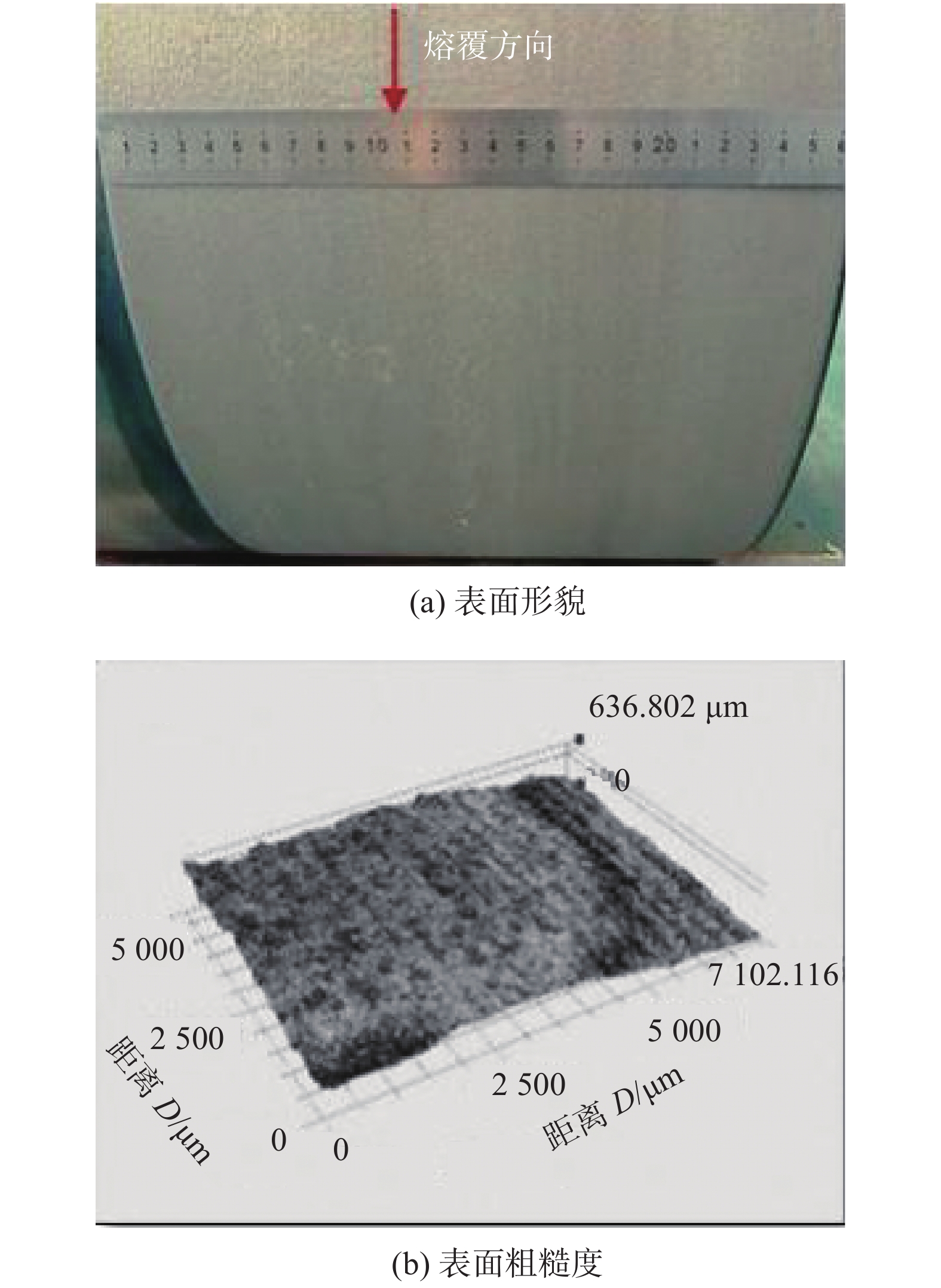
图 1 试样A熔覆层的表面形貌和粗糙度
Figure 1. Surface morphology and roughness of Co-based coatings of sample A. (a) surface morphology; (b) surface roughness
![]()
图 2 试样B熔覆层的表面形貌与粗糙度
Figure 2. Surface morphology and roughness of Co-based coatings of sample B. (a) surface morphology; (b) surface roughness
![]()
图 3 熔覆层横剖面形貌
Figure 3. Cross-section morphology of cladding layer. (a) sample A; (b) sample B
![]()
图 4 熔覆层中部组织 SEM 照片
Figure 4. SEM morphology of middle part of Co-basedcoatings. (a) sample A; (b) sample B
![]()
图 5 试样A熔覆层元素过渡区的EDS分析结果
Figure 5. EDS analysis of element transition zone in cladding layer of sample A. (a) line scanning area; (b) element distribution
![]()
图 6 试样B熔覆层元素过渡区的EDS分析
Figure 6. EDS analysis of element transition zone in cladding layer of sample B. (a) line scanning area; (b) element distribution
![]()
图 7 熔覆层枝晶的显微组织形貌
Figure 7. Microstructure morphology of dendrites of Co-based coatings. (a) sample A; (b) sample B
![]()
图 8 熔覆层与基材磨痕的OM照片
Figure 8. OM images of Co-based coatings and substrate wear scar. (a) substrate; (b) sample A; (c) sample B
![]()
图 9 熔覆层与基材磨痕的SEM照片
Figure 9. SEM images of Co-based coatings and substrate wear scar. (a) substrate; (b) sample A; (c) sample B
![]()
图 11 熔覆层与基材的磨痕的中心深度
Figure 11. Center depth of Co-based coatings and substrate wear scar. (a) substrate; (b) sample A; (c) sample B
![]()
图 12 熔覆层与基材磨痕的平面投影形貌
Figure 12. Plane projection topography of Co-based coatings and substrate wear scar. (a) substrate; (b) sample A; (c) sample B
表 1 Co基合金粉末的化学成分(质量分数,%)
Table 1 Chemical composition of Co-based powder
C Cr Si Fe W Ni Mo Mn Co 1.14 29.95 1.26 1.92 5.47 2.31 0.65 0.24 余量  下载: 导出CSV
表 2 优化后的激光熔覆工艺参数
Table 2 Optimized laser cladding process parameters
试样 功率
P/kW熔覆速度
v/(m·min−1)离焦量
f/mm搭接率
η(%)A 2.5 15 5 83 B 1.35 0.6 5 50
下载: 导出CSV
位置 Co Cr Fe Si C a 58.17 24.81 5.67 0.95 5.51 b 46.81 31.83 3.68 0.73 10.37 c 40.61 19.84 25.88 1.06 6.17 d 25.64 27.68 16.96 — 12.59
下载: 导出CSV
位置 Co Cr O Ni Fe W Si C e — 16.51 24.33 — 59.15 — — — f — 1.29 27.37 — 68.03 — — 3.31 g 40.79 16.91 23.15 — 14.31 1.95 — 2.89 h 32.57 16.15 25.62 — 17.39 2.36 0.74 4.9 i 30.32 19.24 24.67 4.57 12.68 3.04 1.04 1.09 j 39.47 14.56 23.69 3.28 10.48 2 0.85 5.67
下载: 导出CSV
-
[1] Haga T, Suzuki S. A high speed twin roll caster for aluminum alloy strip[J]. Journal of Materials Processing Technology, 2001, 113(1): 291 − 295.
[2] 刘素华. 铸轧辊辊套使用寿命的探讨[J]. 轻合金加工技术, 2009, 37(9): 34 − 35. Liu Suhua. Discussion on the service life of casting roll sleeve[J]. Light Alloy Fabrication Technology, 2009, 37(9): 34 − 35.
[3] 张晓东, 董世运, 王志坚, 等. 激光再制造金属零件熔覆层组织及耐磨性能[J]. 焊接学报, 2010, 31(2): 75 − 77. Zhang Xiaodong, Dong Shiyun, Wang Zhijian, et al. Microstructure and wear resistance of laser remanufacturing metal parts[J]. Transactions of the China Welding Institution, 2010, 31(2): 75 − 77.
[4] 员霄, 王井, 朱青海, 等. H13钢的铁基和钴基熔覆层组织与耐磨性[J]. 焊接学报, 2018, 39(12): 105 − 109. doi: 10.12073/j.hjxb.2018390307 Yun Xiao, Wang Jing, Zhu Qinghai, et al. Microstructure and abrasion resistance of Fe-based and Co-based coatings of AISI H13[J]. Transactions of the China Welding Institution, 2018, 39(12): 105 − 109. doi: 10.12073/j.hjxb.2018390307
[5] 张春华, 张松, 李春彦, 等. 热作模具钢表面激光熔覆StelliteX-40钴基合金[J]. 焊接学报, 2005, 26(1): 17 − 21. Zhang Chunhua, Zhang Song, Li Chunyan, et al. Laser cladding Stellite X-40 Co-based alloy on hot die steel[J]. Transactions of the China Welding Institution, 2005, 26(1): 17 − 21.
[6] 李俐群, 申发明, 周远东, 等. 超高速激光熔覆与常规激光熔431不锈钢涂层微观组织和耐蚀性的对比[J]. 中国激光, 2019, 46(10): 174 − 183. Li Liqun, Shen Faming, Zhou Yuandong, et al. Comparison of microstructure and corrosion resistance of 431 stainless steel coatings prepared by extreme high-speed laser cladding and conventional laser cladding[J]. Chinese Journal of Lasers, 2019, 46(10): 174 − 183.
[7] 袁庆龙, 冯旭东, 曹晶晶, 等. 激光熔覆技术研究进展[J]. 材料导报, 2010, 24(3): 112-116. Yuan Qinglong, Feng Xudong, Cao Jingjing, et al. Research progress in lasear cladding technology[J]. Materials Review, 2010, 24(3): 112 − 116.
[8] 娄丽艳, 张煜, 徐庆龙, 等. 超高速激光熔覆低稀释率金属涂层微观组织及性能[ J]. 中国表面工程, 2020, 33(2): 149-159. Lou Liyan, Zhang Yu, Xu Qinglong, et al. Microstructure and properties of metallic coatings with low dilution ratio by high speed laser cladding[ J]. China Surface Engineering, 2020, 33( 2): 149-159.
[9] Li Liqun, Shen Faming, Zhou Yuandong, et al. Comparative study of stainless steel AISI 431 coatings prepared by extreme-high-speed and conventional laser cladding[J]. Journal of Laser Applications, 2019, 31(4): 042009. doi: 10.2351/1.5094378
[10] 崔岗, 韩彬, 崔娜, 等. 扫描速度对激光熔覆Ni基WC合金涂层组织与性能的影响[J]. 中国表面工程, 2014, 27(4): 82 − 88. doi: 10.3969/j.issn.1007-9289.2014.04.013 Cui Gang, Han Bin, Cui Na, et al. Effects of scanning speed on microstructure and properties of laser cladding Ni-based WC alloy coating[J]. China Surface Engineering, 2014, 27(4): 82 − 88. doi: 10.3969/j.issn.1007-9289.2014.04.013
[11] Song L J, Zeng G C, Xiao H, et al. Repair of 304 stainless steel by laser cladding with 316L stainless steel powders followed by laser surface alloying with WC powders[J]. Journal of Manufacturing Processes, 2016, 24(1): 116 − 124.
[12] 澹台凡亮, 田洪芳, 陈峰, 等. 高速激光熔覆在27SiMn液压支架立柱上的应用探讨[J]. 新技术新工艺, 2019(3): 52 − 54. Tantai Fanliang, Tian Hongfang, Chen Feng, et al. Discussion on application of high-speed laser cladding on 27SiMn hydraulic support column[J]. New Technology & New Process, 2019(3): 52 − 54.
[13] 张煜, 娄丽艳, 徐庆龙, 等. 超高速激光熔覆镍基WC涂层的显微结构与耐磨性能[J]. 金属学报, 2020, 56( 11): 1530-1541. Zhang Yu, Lou Liyan, Xu Qinglong, et al. Microstructure and wear resistance of Ni-based WC coating by ultra-high speed laser cladding[ J]. Acta Metallurgica Sinica, 2020, 56(11): 1530-1541.
-
期刊类型引用(3)
1. 张明军,李晨希,邹江林,程波,张健,仝永刚,胡永乐,陈根余. AZ31B镁合金功率调制环形光斑光纤激光焊接试验研究. 机械工程学报. 2025(02): 151-161 .  百度学术
百度学术
2. 刘坤,李洁,王浩,简思捷. 镁合金焊接凝固裂纹敏感性评价及晶间液相回填规律分析. 焊接学报. 2023(09): 9-15+129 . 本站查看
3. 焦婧,黄金鑫,张志凯. 论带复杂油路类镁合金铸件的清理方法. 世界有色金属. 2022(23): 175-177 . 百度学术
其他类型引用(2)


计量
- 文章访问数: 351
- HTML全文浏览量: 19
- PDF下载量: 40
- 被引次数: 5
