高级检索

等离子弧增材制造双金属交织结构微观组织及力学性能

郭顺, 王鹏翔, 周琦, 朱军, 顾介仁

郭顺, 王鹏翔, 周琦, 朱军, 顾介仁. 等离子弧增材制造双金属交织结构微观组织及力学性能[J]. 焊接学报, 2021, 42(3): 14-19. DOI: 10.12073/j.hjxb.20201125004
引用本文: 郭顺, 王鹏翔, 周琦, 朱军, 顾介仁. 等离子弧增材制造双金属交织结构微观组织及力学性能[J]. 焊接学报, 2021, 42(3): 14-19. DOI: 10.12073/j.hjxb.20201125004
GUO Shun, WANG Pengxiang, ZHOU Qi, ZHU Jun, GU Jieren. Microstructure and mechanical properties of bimetallic intertexture structure fabricated by plasma arc additive manufacturing[J]. TRANSACTIONS OF THE CHINA WELDING INSTITUTION, 2021, 42(3): 14-19. DOI: 10.12073/j.hjxb.20201125004
Citation: GUO Shun, WANG Pengxiang, ZHOU Qi, ZHU Jun, GU Jieren. Microstructure and mechanical properties of bimetallic intertexture structure fabricated by plasma arc additive manufacturing[J]. TRANSACTIONS OF THE CHINA WELDING INSTITUTION, 2021, 42(3): 14-19. DOI: 10.12073/j.hjxb.20201125004

等离子弧增材制造双金属交织结构微观组织及力学性能

基金项目: 国家自然科学基金资助项目(51805266);江苏省先进结构材料与应用技术重点实验室开放基金资助项目(ASMA201906).
详细信息
    作者简介:

    郭 顺,博士,讲师;主要从事高能束/电弧焊接及增材工艺/性能/表征等方面研究;Email:guos09@njust.edu.cn.

    通讯作者:

    周琦,博士,教授,博士研究生导师; Email:cheezhou@njust.edu.cn.

  • 中图分类号: TG 444.2

Microstructure and mechanical properties of bimetallic intertexture structure fabricated by plasma arc additive manufacturing

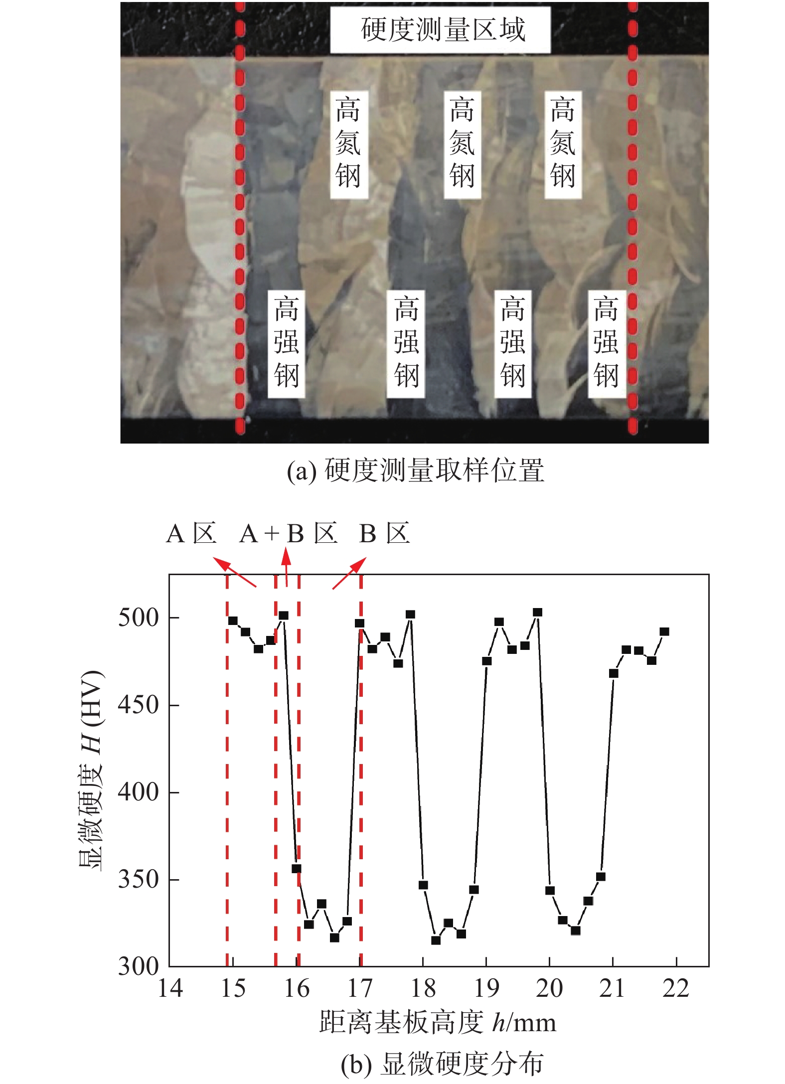
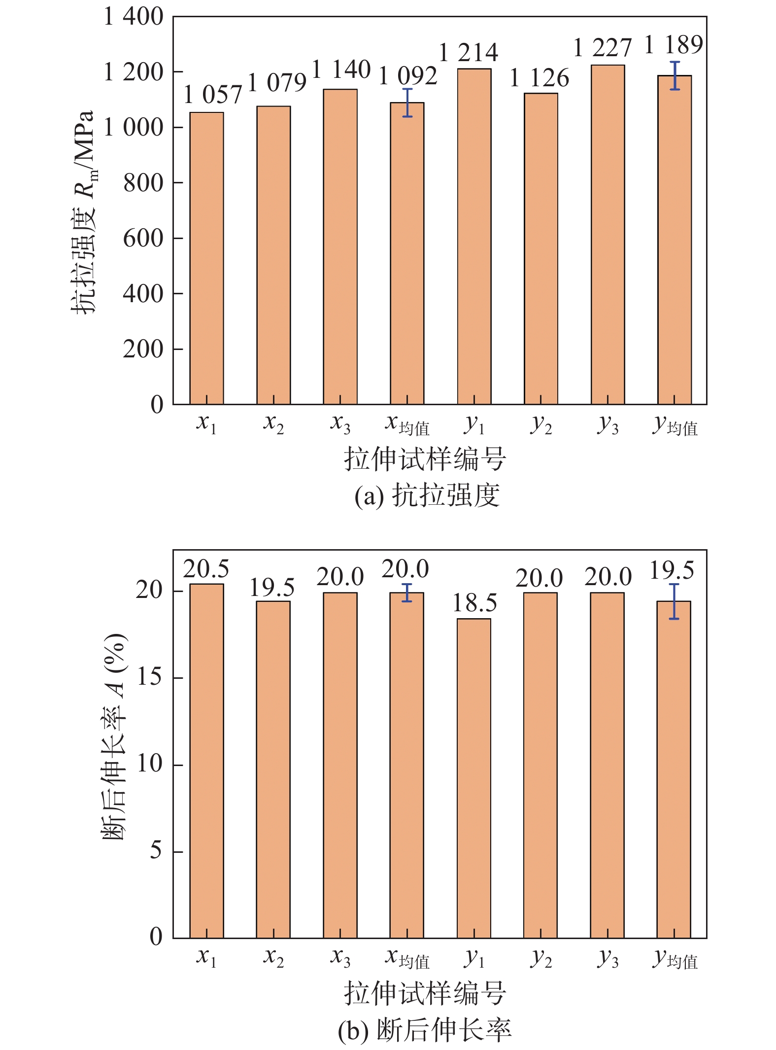
  • 摘要: 以18Ni高强钢和高氮奥氏体不锈钢为丝材,采用等离子弧增材制造高强钢-高氮钢双金属交织结构,通过对高强钢-高氮钢双金属交织结构的微观组织观察、显微硬度及抗拉强度等力学性能试验研究了双金属交织结构的组织转变特征及其与力学性能关系. 结果表明,在高氮钢区域显微组织主要为奥氏体等轴晶及树枝晶,高强钢区域为板条状马氏体. 高强钢区域硬度变化范围为480 ~ 500 HV;高氮钢区域硬度变化范围为310 ~ 320 HV. 拉伸试验结果表明,交织结构在x向抗拉强度均值为1 092 MPa,略低于y向抗拉强度1 189 MPa;x向断后伸长率均值为20.0%,与y向断后伸长率19.5%相差不大;断口呈暗灰色、明显纤维状,分布有大量的等轴韧窝,韧窝尺寸大而深,断口边缘存在明显剪切唇区,属于韧性断裂.
    Abstract: Using 18Ni high strength steel and high nitrogen austenitic stainless steel as wires, bimetallic intertexture structure of high strength steel and high nitrogen steel was fabricated by plasma arc additive manufacturing. The microstructure and mechanical properties of bimetallic intertexture structure of high strength steel and high nitrogen steel were studied by microstructure observation, microhardness and tensile strength test. The results indicate that the microstructure in high nitrogen steel region are mainly equiaxed crystals and dendrite of austenite, the microstructure of high strength steel area is lath martensite. The hardness of the high strength steel area varies from 480 to 500 HV, the hardness of high nitrogen steel area varies from 310 to 320 HV. The tensile test results show that the average tensile strength of the intertexture structure in the x direction is 1 092 MPa, which is slightly less than the tensile strength in the y direction of 1 189 MPa. The average elongation after fracture in the x direction is 20.0%, which is not much different from the elongation after fracture in the y direction which is 19.5%. The fracture presents dark gray and obviously fibrous, with a large number of equiaxed dimples distributed, the dimples are large and deep, and there is an obvious shear lip area on the edge of the fracture, which is a ductile fracture.
  • Ti600合金名义成分为Ti-6Al-2.8Sn-4Zr-0.5Mo-0.4Si-0.1Y (质量分数,%),具有高温强度高、抗蠕变性能好、疲劳性能优异等特点,可服役于600 ℃无强度损失,是一种性能优异的轻质高温合金,可应用于航空航天领域[1]. 但是钛合金由于自身抗氧化性能差限制了其广泛应用. Ni-25%Si (原子分数,%)合金具有优异的抗氧化性和高温强度,可工作于700 ℃[2]. 如果实现Ti600和Ni-25%Si合金的连接便可最大程度发挥二者的优势.

    由Ni-Ti-Si三元相图[3]可知,Ni-Ti-Si三元体系可生成20种脆性金属间化合物,导致Ti600和Ni-25%Si合金焊接性差,焊后开裂风险高. Yue等人[4]和Liu等人[5]的研究表明,对于化学性质差异大的异种金属,钎焊和扩散焊是有效的连接方法. 其中相比于扩散焊,钎焊成本低、操作简单[6]、冶金调控性好[7],是最有可能实现Ti600和Ni-25%Si合金高强连接的方法之一. 目前已有国内外学者对涉及Ni-Ti-Si三元体系的钎焊过程进行了研究. 如Yang等人[8]对SiC和TiAl的钎焊连接研究表明,采用Ti-Ni钎料焊接时可避免硅化物的产生,可将Ni-Ti-Si三元反应体系降维为Ti-Ni二元体系. 但Li等人[9]对SiC,Ni,Ti钎焊体系的研究结果表明硅化物的产生不可避免. 上述研究说明钎焊的试验条件对Ni-Ti-Si三元反应体系具有重要影响. 所以,为了探索Ti600、Ti-Zr-Ni-Cu钎料、Ni-25%Si合金组成的钎焊体系的反应特征,前期对Ti600/Ti-Zr-Ni-Cu/Ni-25%Si钎焊接头的典型组织进行了分析并阐明了典型界面层及反应产物的形成机理[10]. 但是钎焊温度对Ti600和Ni-25%Si合金界面结构及接头力学性能的影响规律还未见详细报道,仍需进一步研究.

    为了揭示钎焊温度对Ti600和Ni-25%Si合金界面结构及接头力学性能的影响规律,采用透射电镜、扫描电镜、抗剪强度测试等分析测试手段研究不同钎焊温度下的界面演化规律及接头抗剪性能响应,建立钎焊温度、界面结构、力学性能的关系模型. 同时,对接头断口形貌进行分析,研究不同钎焊温度下所得接头的失效行为,阐明接头的断裂机制.

    试验材料Ni-25%Si合金为镍基固溶体片层、Ni3Si片层、Ni31Si12片层周期性排列组成的全片层材料,这种结构能够有效增强Ni-25%Si合金的强度和韧性,其典型组织如图1所示. 首先将Ni-25%Si合金和Ti600合金通过线切割分别切成 5 mm × 5 mm × 5 mm和10 mm × 20 mm × 2 mm块状试样. 非晶钎料Ti-Zr-Ni-Cu成分为Ti-38.65Zr-10.1Ni-15.7 Cu,厚度为50 μm,熔化区间为750 ~ 1 010 ℃. 焊前分别对两种母材进行打磨、清洗,并按照图2中顺序装配放入真空室中. 为了探明连接温度对合金接头组织性能的影响,分别选择900,920,940,960和980 ℃进行钎焊试验,保温时间10 min.

    图  1  全片层Ni-25%Si合金微观组织
    Figure  1.  Typical morphology of the full lamella Ni-25%Si alloys
    图  2  钎焊接头装配示意图
    Figure  2.  Schematic diagram of the brazed joint

    焊接完成后,采用线切割切取金相试样,随后采用扫描电镜(SEM, Quanta 200FEG)分析不同工艺参数下钎焊接头的界面结构特征及断口特征. 通过能谱分析(EDS, Genesis Apollo X/XL)确定界面各物相的成分,并结合断口的X-射线衍射结果(XRD, D8 ADVANCE)分析物相种类. 通过透射电镜(TEM, Talos F200x)精确分析界面尺寸较小的反应层,透射电镜试样由聚焦离子束(FIB)制备. 通过万能测试机(Instron 5967)分析钎焊接头的抗剪强度,评价接头的焊接质量.

    图3为典型的Ti600/Ni-25%Si接头界面形貌. 钎焊接头可划分为6个区域,记作I,II,III,IV,V和VI,其中VI区为IV和V区间的的薄层,如图3d所示. 由表1的EDS分析结果可知,接头两侧为扩散反应层,为α-Ti+β-Ti和Ni31Si12相;接头内部的基体为Ti2Ni相;靠近Ti600母材的区域还存在Ti3Al、(Ti, Zr)2(Ni, Cu)和(Ti, Zr)2Si等金属间化合物;靠近Ni-25%Si侧的基体上只含有Ti5Si3一种金属间化合物;另外,接头内部还检测到微量的α-Ti+β-Ti. 由于VI区域较小,能谱无法精确分析其内部. 因此选择透射电子显微镜对该区域进行分析. 图4为VI区的TEM图片和其内部各相的选区电子衍射花样. 由图4可知,VI区近IV区侧由TiNi相和弥散分布的Ti5Si3相组成,靠近V区的一侧为Ti3Ni和Ti6Ni16Si7反应层. 笔者前期重点对上述各物相的形成机制进行了研究[10],在此不再赘述.

    图  3  钎焊接头(940 ℃/10 min)界面组织结构及区域放大形貌
    Figure  3.  Interface structure of brazed joint (940 ℃/10 min) and area enlargement images. (a) interface structure of the joint brazed at 940 ℃ for 10 min; (b) zone I and II; (c) zone III; (d) zone IV, V and VI
    表  1  接头内部各点EDS分析结果及可能相(原子分数,%)
    Table  1.  Chemical composition and possible phase of each spot in the joint
    AlSiZrSnTiNiCu可能相
    A 11.00 1.58 1.84 1.57 76.38 6.55 1.07 α-Ti+β-Ti
    B 15.21 1.35 0.99 8.53 71.87 1.42 0.63 Ti3Al
    C 5.06 0.70 2.52 0.22 56.65 31.46 3.39 Ti2Ni
    D 6.71 1.08 7.58 0.72 55.84 18.11 9.96 (Ti,Zr)2(Cu,Ni)
    E 9.74 0.69 2.75 1.48 72.91 6.49 5.94 α-Ti+β-Ti
    F 2.26 29.41 27.79 1.89 30.10 5.73 2.82 (Ti,Zr)2Si
    G 14.45 1.34 1.44 1.48 73.37 4.19 3.73 α-Ti+β-Ti
    H 1.64 34.99 3.09 0.33 56.98 2.41 0.55 Ti5Si3
    I 0.63 27.16 0.07 0.29 0.31 69.68 1.85 Ti31Si12
    J 10.98 2.06 1.85 1.95 72.51 4.88 5.78 α-Ti+β-Ti
    下载: 导出CSV 
    | 显示表格
    图  4  透射电子显微镜明场像及各部分选区电子衍射分析
    Figure  4.  TEM and SAED images. (a) zone IV and VI; (b) zone VI and V

    图5为不同连接温度下获得的接头界面组织形貌图. 可以看出接头尺寸随着钎焊温度的改变发生了明显的变化. 钎焊温度为900 ℃时接头尺寸仅为70 μm,而钎焊温度上升至980 ℃时接头尺寸增加到约450 μm,说明钎焊过程中温度上升能够促进母材与钎料相互作用,有助于母材向接头溶解和扩散. 同时,钎焊温度的提高也增加了V区反应层内部的孔洞缺陷数量. 根据文献[11]可知,Ni-Ni间的金属键键能在Ni-Si体系内远低于Ni-Si之间的共价键键能,所以Ni的扩散占主导地位. 同时钎焊温度的上升能够进一步促进Ni原子的扩散,增加孔洞的大小和数量,因此孔洞易于在高钎焊温度下形成.

    图  5  钎焊温度对钎缝界面组织的影响
    Figure  5.  Effect of brazing temperature on microstructures of the joints. (a) 900 ℃; (b) 920 ℃; (c) 940 ℃; (d) 960 ℃; (e) 980 ℃

    图5a图5b所示,钎焊温度低于920 ℃,接头由两个部分组成,靠近钛合金的区域为Ti2Ni基体和大量的(Ti,Zr)2(Ni,Cu),而靠近镍硅合金侧的区域则为Ti2Ni和(Ti,Zr)2Si相. 图5c为钎焊温度940 ℃时的典型接头形貌,可以看出接头近Ni-25%Si母材的位置上出现了包含Ti2Ni和Ti5Si3相的Ⅳ区,其中Ti5Si3相颗粒弥散分布在Ti2Ni相上. 同时,靠近Ti600母材的接头界面上也析出了球形Ti3Al相. 如图5d图5e所示,连接温度在960 ℃以上时,(Ti,Zr)2Si和Ti2Ni相组成的III区渐渐消失,而Ni-25%Si母材侧包含Ti2Ni和Ti5Si3的IV区逐渐扩大,最终占据全部钎缝. 界面上析出的球形Ti3Al相数量也随温度的上升逐渐增加. 钎焊接头是由两侧母材与熔融钎料之间的剧烈反应所得,钎焊温度的增加会促进母材的溶解以及焊缝内元素的扩散. 一方面,Zr元素在高温的促进下能够在焊缝内充分扩散;另一方面,两侧母材的溶解也会稀释焊缝内的Zr元素并富集Ni,Ti和Si元素. 因此,当钎焊温度升高至960 ℃以上时,钎缝中由(Ti,Zr)2Si和Ti2Ni相所构成的III区便逐渐被包含Ti2Ni和Ti5Si3相的IV区取代.

    图6为在不同钎焊温度下得到的接头室温抗剪强度关系图. 可以看出随着温度的增加,接头抗剪强度有所提高,当钎焊温度达到960 ℃时,抗剪强度出现阶跃式上升达到峰值177 MPa;进一步提高钎焊温度抗剪强度则有所下降,980 ℃时所得的接头抗剪强度降低至112 MPa,远大于940 ℃时的43 MPa. 结合图5的微观结构和图6的抗剪强度可知,含有Ti5Si3和Ti2Ni相的接头具有更高的强度.

    图  6  不同钎焊温度下所得接头的抗剪强度
    Figure  6.  Shear strength of joints brazed at different temperature

    图7为不同钎焊温度下所得接头的宏观剪切断口形貌. 可以发现各个断口均属于脆性解理断裂,并且存在两个典型区域,分别是位于Ni-25%Si侧断口边缘的区域和位于Ti600侧断口中心的区域. 图8为不同钎焊温度下微观剪切断口SEM图片. 从图8a可以看出,相较于断口边缘区,断口中心区处具有大面积光滑区域,说明裂纹扩展长大时在断口边缘受到的阻碍更大. 从图8c可以看出,强规范(钎焊温度高于960 ℃)工艺条件下获得的断口边缘区域存在与V区内一致的孔洞缺陷,由此可知断口边缘位于V区. 对比不同工艺下的接头断口中心可知,随着钎焊温度的提高,接头断口中心粗糙度上升,这表明在强规范工艺条件下制备的试样断口中心对裂纹扩展的阻碍作用更强.

    图  7  不同钎焊温度下接头宏观剪切断口形貌
    Figure  7.  Fracture morphologies brazed by different temperature. (a) 920 ℃/10 min; (b) 940 ℃/10 min; (c) 960 ℃ /10 min
    图  8  不同钎焊温度下的接头微观断口形貌
    Figure  8.  Fracture morphologies brazed by different temperature. (a) SEM images of the fracture surface brazed by 940 ℃/10 min; (b) the edge of fracture surface obtained by 960 ℃ /10 min; (c) the middle of fracture surface obtained by at 960 ℃/10 min; (d) the middle of fracture surface obtained by at 980 ℃/10 min

    对断口进行XRD和EDS分析. 如图9所示,各断口均含有Ti2N和Ni31Si12相. 结合表2的EDS分析可知,断口边缘V区主要为Ni31Si12相(A点和C点),与前文结论相同. 断口中心主要为Ti2Ni相(B点,D点和F点). 但是能谱分析发现了在强规范下断口中心区域含有Ti5Si3相,这在XRD测试时并没有检测到,这是因为Ti5Si3相的含量较少以至于无法出现衍射峰.

    图  9  不同工艺条件下接头断口的X射线衍射结果
    Figure  9.  XRD results of fracture surface of different joints

    表2的EDS结果与图7图8a中的大面积光滑断面对应可知,弱规范下(钎焊温度低于940 ℃)获得的接头断口中心位于II区内. 而在强规范时,大量的Ti2Ni相和零星的Ti5Si3相表明此时断口中心位于Ⅳ区偏II区的位置. Xia等人[12]的研究表明,应力集中主要出现在钎焊接头的边缘区域. 所以在剪切过程中,裂纹首先在接头边缘形核再逐渐长大最后扩展到钎缝内部. 具体断裂示意图如图10所示,接头首先在V区开裂,弱规范下下裂纹扩展到II区,而强规范下裂纹则会扩展到IV区.

    表  2  钎焊接头断口的EDS结果和可能相(原子分数,%)
    Table  2.  The ESD results and possible phase of the surface of d joints
    AlSiZrSnTiNiCu可能相
    A 0.22 26.90 0.11 0.41 0.39 70.20 1.77 Ni31Si2
    B 4.19 1.07 3.44 0.66 57.28 29.31 4.06 Ti2Ni
    C 1.10 28.12 0.00 0.22 0.61 68.42 1.53 Ni31Si12
    D 6.44 7.61 2.75 0.57 54.01 26.67 1.93 Ti2Ni
    E 4.07 30.90 6.13 0.47 52.51 4.79 1.13 Ti5Si3
    F 4.26 0.68 1.44 0.36 58.65 32.64 1.96 Ti2Ni
    下载: 导出CSV 
    | 显示表格
    图  10  裂纹扩展示意图
    Figure  10.  Schematic diagrams of the crack propagation path of the joints obtained. (a) below 940 ℃; (b) above 940 ℃

    应力集中是导致裂纹从接头边缘向内部偏转的主要原因. 钎焊接头的残余应力可表示为[13]

    $${\sigma _r} = \frac{{{E_A}{E_B}}}{{{E_A} + {E_B}}}\left( {{\alpha _A} - {\alpha _B}} \right)\Delta T$$ (1)

    式中:σr为残余热应力;E为弹性模量;α为热膨胀系数;∆T为温度差. 两种材料的热膨胀系数差异越大,钎焊后所得的接头残余应力越大. 表3为接头处主要相的线膨胀系数和弹性模量. 带入式(1)计算可知,接头的峰值残余应力出现在Ti600和Ti2Ni相之间,所以裂纹在V区出现后向Ti600和Ti2Ni侧偏转.

    表  3  接头两侧主要相的线膨胀系数与弹性模量
    Table  3.  CTE and Elastic modulus of the main phase near the brazing interface
    主要相线膨胀系数δ/(10−6 −1)弹性模量E/GPa
    TiN216115
    Ti6008.5109
    Ni-25%Si11.97259
    下载: 导出CSV 
    | 显示表格

    Zuhailawati[14]和He[15]等人的研究表明,连续的Ti2Ni相无法阻止裂纹长大,裂纹形核便会扩展从而使工件失效. 钎焊温度低于940 ℃时,II区产生连续的Ti2Ni相,因此抗剪强度较低. 而钎焊温度较高时,断口中心则在IV区内(图11). 从图11b可以看出,析出的Ti5Si3晶须在Ti2Ni晶界上互相连接,形成了具有连续网状分布的强化晶界. 这种连续网状分布的强化相能够显著提高基体的性能,阻碍裂纹扩展,Ti2Ni相的强度也能得到提高. 因此,强规范工艺下制备的钎焊接头抗剪强度远高于弱规范下制备的接头抗剪强度. 如图12所示,尽管钎焊在强规范下的接头的V区具有许多孔洞,但它们的抗剪强度仍高于弱规范下的的接头. 裂纹扩展时受到孔洞的影响出现钝化,也是造成这种现象的原因.

    图  11  IV区连续网状分布的Ti5Si3强化晶界(960 ℃/10 min)
    Figure  11.  Net-shaped reinforcement phase existing in zone IV(960 ℃/10 min). (a) the brazing joint; (b) the net-shaped reinforcement phase existing in zone IV
    图  12  V区内部裂纹拓展和钝化
    Figure  12.  Crack deflecting and crack blunting in zone V

    (1)对Ti600和Ni-25%Si合金进行钎焊试验,分析了高温钛合金与镍硅合金钎焊接头的性能及失效机理.

    (2)钎焊温度为900 ℃时接头尺寸仅为70 μm,而钎焊温度为980 ℃时接头尺寸增加到450 μm,强规范下Ⅴ区会出现孔洞.

    (3)钎焊温度在960 ℃以上时,(Ti,Zr)2Si和Ti2Ni相组成的区域渐渐被Ti2N和Ti5Si3相覆盖. 强规范下会形成球形Ti3Al相.

    (4)钎焊接头的抗剪强度随连接温度的提高先增加后降低,在960 ℃时接头抗剪强度能够达到177 MPa.

  • 图  1   双金属交织结构示意图

    Figure  1.   Schematic diagram of bimetallic intertexture structure. (a) path of additive manufacturing; (b) macroscopic morphology

    图  2   双金属交织结构各区域金相组织

    Figure  2.   Metallographic structure of each area of bimetallic intertexture structure. (a) high nitrogen steel; (b) high strength steel; (c) bimetallic intertexture interface

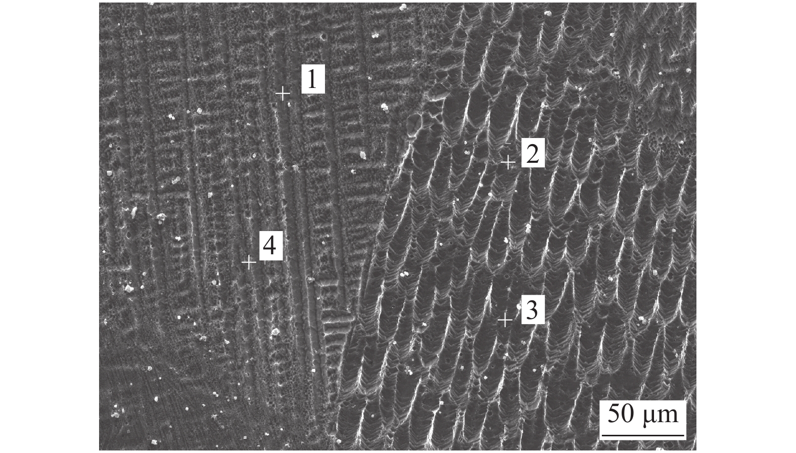
    图  3   交织区域SEM形貌

    Figure  3.   SEM morphology of intertexture area

    图  4   交织结构XRD衍射图谱

    Figure  4.   XRD diffraction pattern of intertexture structure

    图  5   交织结构硬度测试位置及分布

    Figure  5.   Hardness test position and distribution of intertexture structure. (a) hardness test position; (b) microhardness distribution

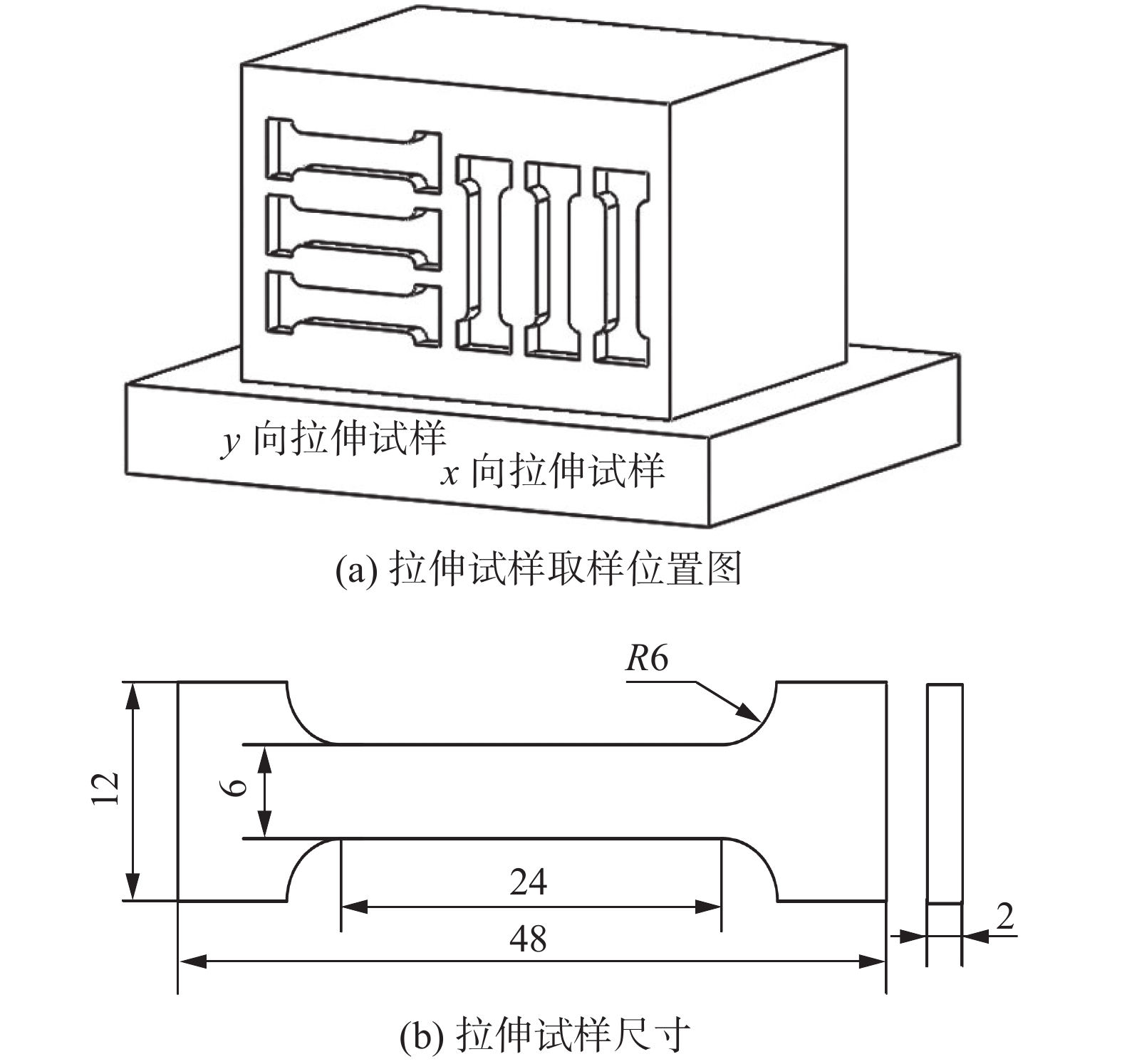
    图  6   双金属交织结构拉伸取样及尺寸(mm)

    Figure  6.   Sampling location and dimension of bimetallic intertexture structure. (a) sampling location of tensile specimen; (b) dimension of tensile specimen

    图  7   增材样件的拉伸结果

    Figure  7.   Tensile test results of additive manufacturing samples. (a) tensile strength; (b) elongation after fracture

    图  8   拉伸试样的断口形貌

    Figure  8.   Fracture morphology of tensile specimen. (a) macro morphology; (b) micro morphology

    表  1   丝材与基板化学元素组成(质量分数,%)

    Table  1   Chemical component of wire and substrate

    材料NiMoCoCrNMnTiCFe
    基板8.0182.00.08余量
    丝材15.372.38210.586.850.027余量
    丝材2184.611.50.11.30.03余量
    下载: 导出CSV

    表  2   等离子弧增材工艺参数

    Table  2   Parameters of plasma arc additive manufacturing

    增材电流I/A增材速度v/(cm·min−1)送丝速度v1/(m·min−1)离子气流量Q1/(L·min−1)保护气体流量Q/(L·min−1)离子气及保护气类型
    120200.81.219纯Ar
    下载: 导出CSV

    表  3   各点化学元素组成(原子分数,%)

    Table  3   Chemical element component of each point

    位置NiMoCoCrMnTiFe
    118.184.7111.711.1563.09
    26.372.3820.976.8162.09
    34.244.5122.765.7460.12
    419.565.2412.011.4561.37
    下载: 导出CSV
  • [1] 杨东青, 熊涵英, 黄勇, 等. 高氮奥氏体焊丝焊接超高强钢接头组织和性能[J]. 焊接学报, 2020, 41(12): 44 − 48. doi: 10.12073/j.hjxb.20200830001

    Yang Dongqing, Xiong Hanying, Hunag Yong, et al. Microstructure and properties of ultra-high strength steel joints welded with high nitrogen austenite wire[J]. Transactions of the China Welding Institution, 2020, 41(12): 44 − 48. doi: 10.12073/j.hjxb.20200830001

    [2]

    Rajkumar V, Arivazhagan N. Role of pulsed current on metallurgical and mechanical properties of dissimilar metal gas tungsten arc welding of maraging steel to low alloy steel[J]. Materials and Design, 2014, 63: 69 − 82. doi: 10.1016/j.matdes.2014.05.055

    [3] 明珠, 王克鸿, 王伟, 等. 焊丝含氮量及焊接电流对高氮钢焊缝组织和性能影响[J]. 焊接学报, 2019, 40(1): 104 − 108. doi: 10.12073/j.hjxb.2019400021

    Ming Zhu, Wang Kehong, Wang Wei, et al. Effects of nitrogen content and welding current on microstructure and properties of the weld of high nitrogen austenite steel[J]. Transactions of the China Welding Institution, 2019, 40(1): 104 − 108. doi: 10.12073/j.hjxb.2019400021

    [4]

    Korobeinikov I, Perminov A, Heller H P, et al. Inert gas atomization of high-nitrogen TRIP-steels[J]. Advanced Engineering Materials, 2019, 21(5): 89 − 97.

    [5]

    Zhang Xiaoyong, Zhou Qi, Wang Kehong, et al. Study on microstructure and tensile properties of high nitrogen Cr-Mn steel processed by CMT wire and arc additive manufacturing[J]. Materials and Design, 2019, 166: 1 − 15.

    [6] 李冬杰, 陆善平, 李殿中, 等. 高氮钢焊缝的组织和冲击性能研究[J]. 金属学报, 2013, 49(2): 129 − 136. doi: 10.3724/SP.J.1037.2012.00514

    Li Dongjie, Lu Shanping, Li Dianzhong, et al. Research on microstructure and impact performance of high nitrogen steel weld[J]. Acta Metallurgica Sinica, 2013, 49(2): 129 − 136. doi: 10.3724/SP.J.1037.2012.00514

    [7]

    Sun Qingjie, Sang Haibo, Liu Yibo, et al. Cross section scan trace planning based on arc additive manufacturing[J]. China Welding, 2019, 28(4): 16 − 21.

    [8]

    Cunningham C R, Flynn J M, Shokrani A, et al. Strategies and processes for high quality wire arc additive manufacturing[J]. Additive Manufacturing, 2018, 22: 672 − 686. doi: 10.1016/j.addma.2018.06.020

    [9]

    Hoefer K, Mayr P. 3DPMD-arc-based additive manufacturing with titanium powder as raw material[J]. China Welding, 2019, 28(1): 11 − 15.

    [10] 刘东宇, 李东, 李凯斌, 等. E36 与 304 电子束焊接接头的组织及性能[J]. 航天制造技术, 2014(6): 29 − 33.

    Liu Dongyu, Li Dong, Li Kaibin, et al. Microstructure and properties of welded joint of E36 steel and 304 stainless steel by electron beam welding[J]. Aeronautical Manufacturing Technology, 2014(6): 29 − 33.

    [11]

    Li J, Li H, Liang Y, et al. The microstructure and mechanical properties of multi-strand, composite welding-wire welded joints of high nitrogen austenitic stainless steel[J]. Materials, 2019, 12(18): 2944 − 2951. doi: 10.3390/ma12182944

    [12] 曹嘉明. 电弧熔丝增材制造高强钢零件工艺基础研究[D]. 武汉: 华中科技大学, 2017.

    Cao Jiaming. Fundamental research on arc fuse additive manufacturing process of high strength steel parts[D]. Wuhan: Huazhong University of Science and Technology, 2017.

  • 期刊类型引用(3)

    1. 陶旭阳,何建萍,徐磊. 超薄板脉冲微束等离子弧焊熔池振荡频率特征. 轻工机械. 2020(03): 24-27+32 . 百度学术
    2. 陶旭阳,何建萍,徐磊. 基于LabView脉冲微束等离子弧焊熔池振荡信息提取. 智能计算机与应用. 2020(03): 371-374 . 百度学术
    3. 顾玉芬,席保龙,李春凯,石玗,代悦,丁彬. 基于熔池振荡的GTAW熔透实时传感与控制. 电焊机. 2020(12): 5-8+108 . 百度学术

    其他类型引用(7)

图(8)  /  表(3)
计量
  • 文章访问数:  478
  • HTML全文浏览量:  31
  • PDF下载量:  56
  • 被引次数: 10
出版历程
  • 收稿日期:  2020-11-24
  • 网络出版日期:  2021-05-14
  • 刊出日期:  2021-03-30

目录

/

返回文章
返回