Nb/Nb55Ti welding process test at the joints of tubes and flanges in superconducting cavities
-
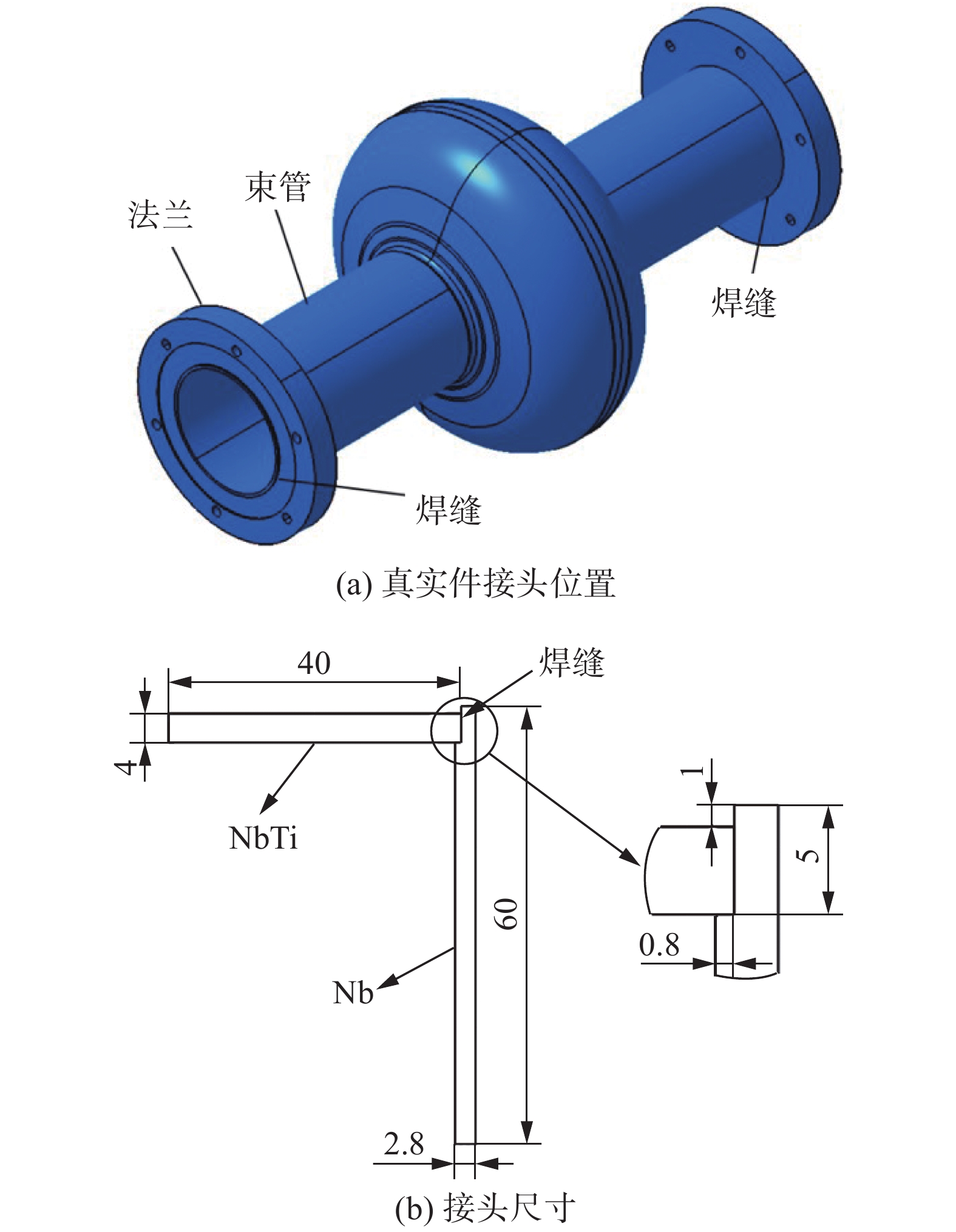
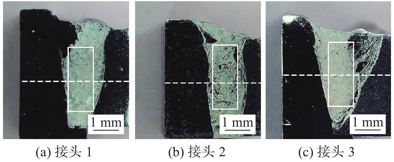
摘要: 超导腔是粒子加速器的核心部件,目前国内外针对超导腔的焊接研究主要集中于半单元间的纯Nb对接接头. 对于超导腔束管与法兰间的焊接研究较少,为了探索该接头处异种材料的焊接工艺,采用Nb板与Nb55Ti板垂直搭成的L形接头来模拟超导腔电子束焊接时束管与法兰的接头,在8,12,20 mA束流下进行试验,焊后对不同束流参数下接头的宏观形貌、微观组织、化学成分和显微硬度进行了对比分析. 结果表明,焊接电流为12 mA时焊缝成形较好,焊接电流较大时Nb侧热影响区晶粒长大较为明显;3组试样焊缝熔化边界处出现了晶粒外延生长的现象,随着焊接电流的提高,熔合线附近出现了粗大的柱状晶;在热输入较大时熔池内液态金属混合充分,焊缝宏观偏析得到改善;焊后Nb侧热影响区显微硬度值出现了明显的下降.Abstract: The superconducting cavity is the core component of the particle accelerator. At present, the welding research of superconducting cavity at home and abroad is mainly focused on the pure niobium butt joints between half cells. There are few studies on the welding between the tube and the flange of the superconducting cavity. In order to explore the welding process of dissimilar materials at this joint, the L-shaped joint assembled vertically by the Nb plate and the Nb55Ti plate was used to simulate the joint between the tube and the flange during the electron beam welding process of superconductingcavity. The tests were carried out under beam currents of 8, 12 and 20 mA respectively. The macroscopic morphology, microstructure, chemical composition and microhardness of the joints under different beam current parameters were compared and analyzed after welding. The results showed that the weld was formed better when the beam current was 12 mA, and the grain growth in the HAZ on the Nb sidewas more obvious when the beam current was high. What’s more, the epitaxial growth of grains at the fusion boundary appeared in 3 groups of joints. As the welding current increased, coarse columnar crystals appeared near the fusion line. When the heat input was large, the liquid metal in the welding pool was fully mixed, which could be improved macrosegregation in the weld. The microhardness of the heat-affected zone on the Nb side decreased significantly after welding.
-
0. 序言
随着纳米材料的广泛应用,以印刷电子为代表的增材制造技术已成为制造电子产品的高效新型技术. 与光刻[1-2]、真空沉积[3-4]和化学镀[5-6]等传统减材制造技术相比,具有低成本、生产效率高、产生废弃物少和环境友好等优点[7-8]. 通过将电子元件集成于柔性基板表面,可赋予电子产品重量轻、可弯曲、灵活、甚至可折叠等特性,使其在下一代柔性电子产品领域具有广泛的应用前景[9].
典型情况下,首先将功能性纳米材料制备成导电油墨,然后将其在柔性基板上结构化,并对所得结构进行固化烧结处理,形成具有电气互联的导电薄膜. 目前常用的导电油墨主要包含纳米金属[10-16]、导电聚合物[17-19]及碳基纳米材料等[20-21]. 其中,纳米金属油墨因其优异的导电性,成为近年来的研究热点. 与其它纳米金属相比(如金[13-14]、铝[15]、镍[21]等),纳米银(Ag)不仅导电性高(电阻率仅约1.59 μΩ·cm),且其化学性质稳定[22],已广泛应用于柔性电子器件的设计及制造中. 然而,高昂的价格及有限的储量限制了Ag导电薄膜的大规模应用[23].
相比而言,铜(Cu)具有与Ag相当的导电性(电阻率为1.68 μΩ·cm),而成本极低,仅为Ag的1%,且储量丰富[24],被认为是银基导电薄膜的良好替代品. 但纳米铜材料的稳定性较差,容易在储存及加工过程中被氧化为氧化亚铜(Cu2O)或氧化铜(CuO),导致所得导电结构的电阻率升高[25]. 为克服这一科学难题,研究人员对其制造、加工方法开展了大量研究.
文中从油墨配方、印刷方法、烧结方法等方面系统地介绍了铜基柔性导电薄膜的制造方法,着重介绍了不同成分油墨的抗氧化策略、不同的烧结方法烧结原理及减少氧化物的原理. 还介绍了铜基柔性导电薄膜在下一代柔性电子产品领域的应用,最后对纳米铜柔性导电薄膜制造尚存的主要问题进行了总结,并对其未来发展趋势进行了展望. 旨在全面而深入地概述铜基柔性导电薄膜,促进铜基柔性导电薄膜的研究和应用.
1. 纳米铜基导电油墨
导电油墨是构建导电结构的基础,与不会被氧化的银纳米粒子油墨不同,铜纳米粒子油墨在空气中极易被氧化,很难稳定存在. 为获得在空气中不易被氧化的铜基导电油墨,目前已开发的铜基导电油墨主要包括纳米铜基粒子油墨、铜氧化物油墨及铜离子前驱体油墨.
纳米铜基粒子通常采用湿化学法(如水热法等[26])合成,通过改变合成过程中反应温度、有机物(如还原剂、封端剂等)种类、有机物浓度等工艺参数,可实现不同性状纳米材料的合成,如纳米颗粒、纳米线等[27]. 然而,铜纳米粒子易在储存过程中发生氧化,其表面形成的氧化物(氧化亚铜及氧化铜)将劣化其电学性能. 研究人员开发了抗氧化纳米铜基粒子的制造方法,以提高其储存过程中的稳定性. 典型的抗氧化纳米粒子为核壳结构,可采用聚合物、碳材料、贵金属材料等作为壳结构,用以阻挡纳米铜粒子与外界有氧环境的接触,达到抗氧化的目的. 由于聚合物较不稳定、碳材料的引入易对最终结构的导电性能产生负面影响,以银为代表的铜@银核壳结构被认为是最佳选择. Zhang等人[28]采用多元醇法制备铜纳米颗粒后,利用铜纳米颗粒与硫酸银间的置换反应制备了铜@银纳米颗粒(如图1a所示),所得纳米颗粒在156 ℃条件下存放40 d后未出现氧化. 类似地,Zhao等人[29]通过水热法合成铜纳米线后,添加硝酸银制备了铜@银纳米线(如图1b所示),该纳米线在140 ℃大气环境条件下保持500 h未发现被氧化. 可以看出,铜@银核壳结构可大幅提高纳米粒子的稳定性,但需精确的调控合成过程中的工艺参数,避免出现铜纳米粒子未被银壳完全包覆的情况. 此外,由于铜、银为不混溶的二元体系,在后续加工过程中极易出现相分离. Zhang等人[28]的研究结果表明,在铜@银纳米颗粒的烧结过程中,Ag壳的互连容易导致纳米铜核的暴露,破坏预制的核壳结构,导致结构在服役中抗氧化性能的下降.
基于氧化铜/氧化亚铜纳米粒子所开发的氧化物纳米油墨可规避其储存过程中的稳定性问题. 通过在预合成的氧化物纳米粒子中添加还原剂等配体,可经由后续的工艺步骤将其还原为铜纳米粒子,实现导电薄膜的制造. 例如,Kang等人[30]在预合成的氧化铜纳米颗粒中添加乙二醇,通过激光辐照所产生的光-热作用将乙二醇分解为甲酸,在还原性羧基(-COOH)的作用下将CuO还原为Cu,最后形成铜导电薄膜. 表1列举了不同铜基油墨制备方法所获得薄膜的导电性能和稳定性的对比[28, 30-41].
表 1 不同铜基油墨制备方法所获得薄膜的导电性能和稳定性的对比Table 1. Comparison of the electrical properties and stability of the resulting films from different copper-based ink processing methods前驱体 基板 印刷—烧结方法 方阻/电阻率 稳定性(温度—时间) 参考文献 铜@银纳米颗粒 玻璃 丝网印刷—热烧结 113 mΩ·sq−1 室温—三周 [31] 铜@银纳米颗粒 玻璃 旋转丝网印刷—热烧结 0.60 Ω·sq−1 室温—两个月 [32] 铜@银纳米颗粒 聚酰亚胺(PI) 喷墨打印—热烧结 3.21 μΩ·cm 156 ℃—40 d [28] 铜@银纳米颗粒 玻璃 喷墨打印—热烧结 11 μΩ·cm NA [33] 铜@银纳米颗粒 玻璃 平面丝网印刷—热烧结 0.18 Ω·sq−1 室温—六个月 [34] 铜@银纳米颗粒 PI 旋转丝网印刷—激光烧结 28.5 μΩ·cm NA [35] 铜@银纳米颗粒 玻璃 旋转丝网印刷—热烧结 13.7 μΩ·cm NA [36] 铜@银纳米线 聚氨基甲酸酯(PU) 喷墨打印—热烧结 35 Ω·sq−1 140 ℃—500 h [37] 铜@金纳米线 玻璃 NA—热烧结 35Ω·sq−1 80 ℃—700 h [38] 氧化铜纳米颗粒 PI NA—激光烧结 31 μΩ·cm NA [30] 氧化铜纳米颗粒 玻璃 旋转丝网印刷—激光烧结 9.5 μΩ·cm NA [39] 氧化铜纳米颗粒 聚乙烯(PE) 喷墨打印—强脉冲光烧结 3.1μΩ·cm NA [40] 氧化铜纳米颗粒 聚对苯二甲酸乙二醇酯(PET) 喷墨打印—强脉冲光烧结 9μΩ·cm NA [41] 注:NA代表不适用. 由于上述结构均采用预合成的纳米结构进行后续加工,具有较为复杂的工艺步骤. 为简化工艺流程,近年来铜离子前驱体油墨受到广大研究人员的青睐[42-43]. 典型的前驱体油墨由铜盐与还原剂等其他配体混合而成,如Draper等人[44]将硝酸铜氢化物和果糖在水中混合制备铜的前驱体油墨,由于铜盐的存在,混合前驱体油墨可以在大气环境条件下保持长期稳定性. 然而,与前述两种油墨相比,铜驱前体油墨中需要的还原剂等配体相对含量较高,在后续加工中易引入孔洞,导致印刷后薄膜的致密度较低、电阻率大,在某些要求高导电的应用中需要进行繁琐的多次涂层才能达到所期望的导电性.
2. 柔性导电薄膜印刷方法
合成导电油墨后,通常需通过印刷步骤将其在目标基板上结构化. 目前用于制造柔性印刷电子设备的印刷方法可分为接触印刷和非接触印刷[45-47]. 接触式印刷技术包括凹版印刷[48]、凹版胶印 [49]、柔版印刷[50]等. 相比而言,非接触式印刷具有操作简单、效率高、对制造过程的适应性强等优点,是目前最常用的柔性印刷电子技术. 典型的非接触式印刷技术包括丝网印刷、喷墨印刷等.
丝网印刷可分为平面丝网印刷和旋转丝网印刷两种类型[51]. 图2a为平面丝网印刷的加工过程示意图,印刷设备通常由刮刀、基板、丝网印版和印刷台组成. 印刷时,在丝网印版的一端倒入油墨,用刮刀对丝网印版上的油墨部位施加一定压力,同时朝丝网印版另一端匀速移动,油墨在移动中被刮板从丝网印版的网孔中挤压到基材上,形成特定的图案. 丝网印版可采用薄片材料、精细多孔织物网和合成纤维/丝绸制成,不仅价格高昂,且针对不同图形化需求时需予以更换. 图2b为旋转丝网印刷(即卷对卷印刷技术),只需要将导电油墨放置在圆筒内,随着两个圆筒的不断转动,内部固定的刮板不断的将油墨挤压流过滚轮上的网孔,印刷在基板上,同时基板也随着滚轮的转动不断地移动,形成特定的图案. 与平面丝网印刷相比,自动化程度高,同时无需每印刷一次就换一次基材,极大地提高了印刷速率,但仍然需要针对不同结构调整印版.
相对于丝网印刷技术,喷墨打印技术的印刷精度可控性高(可达500 nm),且无需印版的参与,有利于降低制造成本. 印刷过程中,通过压电机、电流机或加热油墨所产生的体积压力对喷嘴中的油墨施压,使油墨脉冲喷射于目标基板,配合移动喷嘴,实现油墨在目标基板上的图形化. 图2c, d所示为压电和电流体动力驱动液滴进行印刷的工作机理[52-53]. 其中,压电喷墨是通过电压作用将油墨以墨滴的形式沉积在基板表面,电流体动力喷墨是利用静电场力作用将油墨以连续墨滴流的形式沉积在基板表面. 与压电喷墨相比,电流体驱动喷墨具有喷射速度快、打印效率高等优点,但电流体驱动喷墨对墨滴的控制程度低于压电喷墨,因此打印出图案的精度也低于压电喷墨. 在喷墨印刷中,导电油墨的成分和粘度影响图案的质量,是获得均匀、连续、无缺陷薄膜的关键因素. Gu等人[54]将甘油作为增稠剂加入到铜油墨中,增加油墨粘度而获得均匀、连续和无缺陷的薄膜图案.
然而,与丝网印刷相比,受喷嘴出墨速率的限制,喷墨印刷的效率较低. 此外,纳米铜基粒子和铜氧化物油墨在喷嘴中长时间停留时,油墨中溶剂的挥发易造成纳米粒子的团聚,导致喷嘴间歇性堵塞,降低设备的使用寿命. 无颗粒的铜基离子前驱体油墨开发是喷墨印刷技术发展的未来方向[55].
3. 柔性导电薄膜烧结方法
将导电油墨结构化后,通常需要烧结步骤提高其电学性能. 目前典型的烧结方法有热烧结、光子烧结、等离子烧结、电烧结、化学烧结等.
3.1 热烧结
热烧结[56] (图3)通常利用管式炉或烘箱实现,利用整体的温升将铜纳米材料相互连接,形成电气互联的纳米铜导电薄膜,是目前应用最广的烧结方法之一. 对于预合成纳米铜基离子,其烧结过程所需的温度主要取决于油墨中纳米铜的粒径大小[57],而铜前体油墨的烧结温度主要由还原剂分解温度决定[58]. 由于铜的易氧化特性,需要在惰性气氛、还原气氛或真空下进行热烧结. 其中,还原气氛不仅可以防止铜的氧化,且可促进铜氧化物的还原及封端剂等配体有机物的分解,从而降低铜油墨的烧结温度. 例如,Kim等人[59]以甲酸为还原性气体,在200 °C热烧结铜纳米颗粒油墨1 h后,独立的铜纳米颗粒连接为连续的网状结构,所得薄膜的电阻率可达4.0 μΩ·cm,而在真空条件下325 ℃烧结1 h后,获得铜基导电薄膜电阻率仅达17.2 μΩ·cm[60]. 然而,由于热烧结过程中整体加热的特性,将造成能量的浪费,而200 ℃以上长时间的烧结将易造成热敏性基板的翘曲变形.
![]() 图 3 热烧结工艺示意图(RT表示室温,LT表示低温,HT表示高温)[56]Figure 3. Schematic diagram of the thermal sintering process (RT indicates room temperature, LT indicates low temperature, and HT indicates high temperature)
图 3 热烧结工艺示意图(RT表示室温,LT表示低温,HT表示高温)[56]Figure 3. Schematic diagram of the thermal sintering process (RT indicates room temperature, LT indicates low temperature, and HT indicates high temperature)3.2 光子烧结
光子烧结是近年来广受关注的先进连接技术,可在短时间内实现纳米材料的连接. 由于高温历时短,在加工铜纳米材料时可避免其氧化,在大气环境下即可进行烧结;且由于能量主要由铜油墨吸收,有利于减少能源的浪费及基板的热损伤,具有广泛的应用前景. 光子烧结根据光源类型可划分为强脉冲光(IPL)烧结和激光烧结[61-63].
IPL烧结(图4a)通常采用氙灯作为光源(波长通常为200 ~ 1 000 nm),其烧结规模取决于氙灯的尺寸. Kim等人[64]首次使用IPL烧结铜纳米颗粒油墨,发现仅需照射约2 ms即可完成5 nm铜纳米颗粒的连接,所得薄膜的电阻率低至5.0 μΩ·cm,是在真空中热烧结铜纳米颗粒油墨的三分之一. 在还原剂的辅助下,IPL烧结可实现CuO纳米粒子的还原及烧结. 据Öhlund等人[40]报道,IPL烧结CuO纳米粒子油墨,其烧结过程可在5 ms内完成,所制备的导电薄膜电阻率为3.1 μΩ·cm,仅约铜块材的50%. Wang等人[65]对结构化后的氢氧化铜基油进行IPL烧结,所得薄膜电阻率仅5.27 μΩ·cm. Chung等人[66]对比了多种铜离子油墨(氯化铜、三水硝酸铜、五水硫酸铜、三氟乙酰丙酮)的IPL烧结特性,发现不同的前驱体吸收不同的光波区域,分解温度也根据前驱体的种类而改变. 进一步地,Paglia等人[67]通过调控IPL的能量输入控制CuO纳米颗粒的还原程度,进而控制铜基薄膜中CuO和Cu2O的含量,实现了多价态导电薄膜的制造,有望扩展其应用范围.
区别于IPL烧结,激光烧结(图4b)所采用的光源具有固定的波长,据报道紫外至红外区域的激光均可实现铜基纳米粒子的烧结. 例如,Yu等人[68]使用532 nm波长的激光烧结铜纳米颗粒油墨,图案电阻率低至5.3 μΩ·cm,与在真空中热烧结325 ℃持续1 h相比[60],烧结时间更短,获得的铜基柔性薄膜图案电阻率更低. 在这一过程中,光诱导的等离子共振(SPR)效应仅在纳米结构的结节处引起局部温升,可有效避免整体加热引起的铜结构氧化[69]. 激光也可用于还原-烧结铜氧化物油墨,据Kang等人[30]研究结果显示,在激光诱导所引起的光-热-化学作用下,乙二醇可脱水生成乙醛,所含的还原性羟基(-OH)可以将CuO纳米颗粒还原为Cu纳米颗粒,并原位连接为导电结构. 针对铜离子前驱体油墨,激光提供的热量可以快速分解有机铜盐或无机铜盐基油墨,并且原位形成的小尺寸铜纳米颗粒将在短时间内互连形成稳定的导电结构[70]. 此外,在激光烧结中,也可以通过改变激光的功率调控所得薄膜中铜结构的价态及含量. 本团队Zhou等人[71]基于硝酸铜前驱体油墨进行激光烧结,发现在低能量输入下所得结构表面含有大量铜氧化物纳米颗粒,随着激光功率的升高,铜氧化物还原程度提高,所得结构以铜为主. 相比于IPL烧结,由于激光光斑较小,激光烧结适用于制备高精度的导电结构,但在大面积薄膜结构加工中效率低于IPL烧结.
3.3 其他烧结方法
等离子烧结是利用基态和激发态的电子、离子和中性粒子组成的电离气体轰击可打印材料,实现铜基油墨在低温下的烧结,工艺示意图如图5a所示[72]. 虽然等离子烧结可以实现各种铜油墨的低温连接,但由于基材在加工过程中也受到离子的轰击,容易发生损伤.
电烧结是另一种快速烧结技术,它在整个印刷区域施加电压,产生的电阻热可以让油墨中的有机溶剂蒸发,同时将纳米铜粒子连接为致密的铜基导电薄膜,工艺示意图如图5b所示[73]. 但由于电烧结要求结构在烧结前具有一定导电性,应用场景受到限制;此外,由于通电过程需要与结构相接触,可能造成结构的物理损伤.
如图5c所示,化学烧结通过向油墨材料中添加化学介质(如氯离子)来分解其表面包裹的有机物,使裸露的纳米铜粒子直接接触或将前驱体油墨还原生成纳米铜粒子,通过扩散形成电气互联的导电结构[74-75]. 目前,化学烧结所得结构导电性较差,仅达铜块材的3.3%[75].
4. 纳米铜基柔性导电薄膜典型应用
近年来,纳米铜基柔性导电薄膜已应用于多种电子产品的开发[76-80]. 柔性天线是航空航天、移动通信、遥测、医疗、射频识别标签等无线传感器应用的重要组成部分. 随着无线传感器系统的应用不断扩展(如飞机监控系统、汽车碰撞警告、远程患者监控系统等),人们对无线传输速度的要求不断提高,导电性良好的铜结构被认为是传统铝制天线的替代品. 如今,在塑料基板上已经实现将铜基柔性导电薄膜作为柔性天线使用. 例如,Li等人[76]采用IPL烧结甲酸铜油墨,在PI、聚萘二甲酸乙二醇酯(PEN)和PET基板上制备的V形偶极子铜基柔性薄膜天线图案(如图6a所示). Cu天线长30 mm,宽5 mm,角度约为30°,PI、PEN和PET基板上铜天线的回波损耗(S11)分别为−52,−35,−18 dB,满足实际应用的敏感度.
超级电容器(SCs)具有体积小、薄、灵活、易于集成等优点,已经是日常便携式、可穿戴电子设备中重要的储能单元. SCs由活性电极、电解质、集流体及封装材料组成. 纳米铜基导电薄膜可用于其中集流体的制造,例如,Zhang等人[28]制备的Cu@Ag合金电极具有高电导率(3.21 μΩ·cm)和抗弯折性能,在10 mm半径弯曲2000次后,Cu@Ag的电阻率仅增加33%. 此外,利用铜基材料的赝电容特性,可实现活性电极的制造,例如,本团队Liao等人[77]基于铜离子油墨,采用聚焦激光对其进行选区扫描,制备了铜-石墨烯导电薄膜,所制备的铜-石墨烯复合结构不仅导电性优良(方阻约0.57 Ω·sq−1),且具有较高的电化学活性,进一步组装所得准固态电容器(如图6b所示)的比电容高达13.2 mF·cm−2.
电容屏又称电容式触摸屏,广泛地应用于工业、医疗、通信领域的控制、信息查询等方面. Walia等人[78]将模板法制备的Cu电极与聚二甲基硅氧烷(PDMS)介电层进行组装,完成了柔性电容式触摸屏的制造,如图6c所示. 电容屏不仅透光率高达90%,可以检测手指的接近(量程约20 cm)、触摸、下压(180 kPa以下)及温度(50 ℃以下),且可在弯曲半径2 cm的状态下工作.
集成式柔性葡萄糖电化学传感器具有无痛、重量轻和便携等优点,有望通过体液检测实现人体葡萄糖含量的实时监控. 该类传感器通常由共平面的工作电极、对电极和参比电极组成,传统的工作电极需要葡萄糖氧化酶的活化,可实现葡萄糖的准确测量,但氧化酶的不稳定性影响了器件的稳定性. 本团队Zhou等人[79]基于铜离子前驱体,采用激光直写技术低成本在PI基底上实现了Cu2O/Cu的高效制造. 通过前驱体比例的调控优化了所得结构的成分,所得结构不仅具有低至1.3 Ω·sq−1的方阻,且具有优良的葡萄糖检测活性(如图6d所示),因此可同时用作集流体及工作电极. 与商用的印刷参比电极、对电极配合后,实现了集成式柔性葡萄糖传感器的设计及制造. 所得器件在低至0.3 V的检测电位下的检出限可达0.34 μM,且具有优良的抗干扰性及可弯折性,有望进一步开发为可穿戴葡萄糖传感器.
散热效率是保证电子器件运行速度和可靠性的关键因素,随着电子器件的小型化及高度集成,其热管理面临着越来越大的挑战. 本团队Yao等人[80]采用激光对涂敷于PI表面的铜离子前驱体进行选区辐照,制备了均匀的铜-碳(Cu-C)导热薄膜(如图6e所示),其导热系数可达2.25 W·m−1·K−1,显著高于PI的导热系数(0.1 ~ 0.4 W·m−1·K−1).
5. 总结
综上所述,成本低、性能优良的纳米铜基材料已广泛地应用于柔性导电薄膜制造. 基于油墨性状的调控已开发出数种抗氧化纳米铜基油墨,可有效地提高其稳定性. 通过高效、快速的先进连接技术开发,已实现薄膜成分、结构的调控,可获得高导电性铜基柔性导电薄膜. 然而,核壳铜纳米粒子在连接过程中易发生不期望的结构变化,而基于铜离子油墨所制造薄膜的导电性仍低于预合成纳米粒子,且所得薄膜在长期服役过程中仍存在稳定性欠佳等问题,未来仍需针对油墨组分的优化开展大量研究工作. 此外,先进的烧结技术中所涉的结构连接机理、结构调控机理尚待进一步深入,且其控制精度尚需进一步提高. 目前,虽已开发出多种柔性电子原型器件,但尚处起步阶段,集成化、小型化的高性能多功能柔性电子系统开发是未来研究的发展方向之一.
-
图 6 3组接头EBSD取向分布图
Figure 6. EBSD orientation distribution map of 3 groups of joints. (a) area on the Nb side of joint 1; (b) area on the Nb55Ti side of joint 1; (c) weld center of joint 1; (d) area on the Nb side of joint 2; (e) area on the Nb55Ti side of joint 2; (f) weld center of joint 2; (g) area on the Nb side of joint 3; (h) area on the Nb55Ti side of joint 3; (i) weld center of joint 3
图 7 焊缝中的偏析组织
Figure 7. Segregated structure in the welds. (a) island on the Nb side of the top of the weld of joint 2; (b) peninsula on the Nb side of the middle of the weld of joint 2; (c) island on the middle of the weld of joint 2; (d) island on the Nb55Ti side of the weld of joint 2; (e) peninsula on the top of the weld of joint 1; (f) beach on the Nb55Ti side of the weld of joint 3
表 1 Nb55Ti的化学成分(质量分数,%)
Table 1 Chemical compositions of Nb55Ti
Nb C H O N Fe Ti 44.65 0.001 6 0.001 8 0.078 0.001 1 0.014 余量 表 2 焊接工艺参数
Table 2 Welding process paraments
束流电压Ua/kV 聚焦电流If/mA 焊接速度v/(mm·s−1) 工作距离L/mm 振荡波形 振荡频率fp/Hz 150 2.4 10 300 圆形 500 表 3 图3方框区域EDS点扫描分析结果(原子分数,%)
Table 3 EDS point scan analysis results of box area in Fig. 3
元素 1号样 2号样 3号样 Nb 38.13 41.93 49.30 Ti 60.01 56.34 48.21 其它 1.86 1.73 2.49 表 4 VASP计算得出的β型Ti1−xNbx合金晶格常数(nm)
Table 4 Lattice parameters of β type Ti1−xNbx alloys calculated by VASP
Ti Ti75Nb25 Ti50Nb50 Ti25Nb75 Nb 0.324 7 0.326 0 0.328 4 0.330 1 0.333 2 表 5 母材与焊缝金属计算得到的晶格常数以及对应的晶格失配率
Table 5 Calculated lattice parameters of the base and weld metals and their corresponding lattice misfit
试样 晶格常数a/nm 晶格失配率fNb(%) 晶格失配率fNb55Ti(%) 1号样 0.329 2 1.215 −0.851 2号样 0.328 9 1.307 −0.760 3号样 0.328 3 1.493 −0.579 Nb55Ti 0.326 4 — — 表 6 偏析组织成分的EDS检测结果(原子分数,%)
Table 6 Compositions of segregated structure determined with EDS
元素 1 2 3 4 5 6 7 8 9 10 11 12 13 14 15 16 Nb 72.69 69.49 72.49 73.29 73.55 71.07 78.50 71.60 68.90 68.73 83.05 83.19 52.83 49.80 39.33 40.53 Ti 26.22 29.06 25.48 25.85 24.92 27.81 20.32 27.34 28.89 29.29 15.27 15.04 44.80 47.78 58.12 57.18 其它 1.09 1.45 2.03 0.86 1.53 1.12 1.18 1.06 2.21 1.98 1.68 1.77 2.37 2.42 2.55 2.29 -
[1] Hirotaka Shimizu, Takeshi Dohmae, Masato Egi, et al. Fabrication and evaluation of superconducting single-cell cavities manufactured using various materials and methods[J]. IEEE Transactions on Applied Superconductivity, 2017, 27(7): 3500714.
[2] Singer W. Fabrication of elliptical SRF cavities[J]. Superconductor Science and Technology, 2017, 30(3): 033001. doi: 10.1088/1361-6668/30/3/033001
[3] Cantergiani E, Atieh S, Leaux F, et al. Niobium superconducting rf cavity fabrication by electrohydraulic forming[J]. Physical Review Accelerators and Beams, 2016, 19(11): 114703.
[4] Bieler T R, Wright N T, Pourboghrat F, et al. Physical and mechanical metallurgy of high purity Nb for accelerator cavities[J]. Physical Review Special Topics-Accelerators and Beams, 2010, 13(3): 031002.
[5] Balachandran S, Elwell R, Kang D, et al. Nb tubes for seamless SRF cavities[J]. IEEE Transactions on Applied Superconductivity, 2013, 23(3): 7100904.
[6] Cooley L D, Burk D, Cooper C, et al. Impact of forming, welding, and electropolishing on pitting and the surface finish of SRF cavity niobium[J]. IEEE Transactions on Applied Superconductivity, 2011, 21(3): 2609 − 2614.
[7] Zheng Yongjian, Zhou Lian, Jie Wanqi, et al. Hydrogenation and dehydrogenation analysis for Nb47Ti bars[J]. Rare Metal Materials and Engineering, 2014, 43(11): 2627 − 2630. doi: 10.1016/S1875-5372(15)60015-7
[8] 沈立华, 胡革全, 刘彦昌, 等. 超导用Nb55Ti饼材热处理工艺研究[J]. 热加工工艺, 2019, 48(16): 159 − 161. Shen Lihua, Hu Gequan, Liu Yanchang, et al. Study on heat treatment process of Nb55Ti discs for superconductivity[J]. Hot Working Technology, 2019, 48(16): 159 − 161.
[9] Jung Y, Hyun M, Joung M. RRR characteristics for SRF cavities[J]. Journal of the Korean Physical Society, 2015, 67(8): 1319 − 1323. doi: 10.3938/jkps.67.1319
[10] Jung Y, Joung M. RRR characteristics of niobium along the welding directions for SRF cavities[J]. Journal of the Korean Physical Society, 2016, 69(6): 984 − 988.
[11] Baars D, Jiang H, Bieler T, et al. Crystal orientations near welds in high RRR niobium with very large grains[J]. IEEE Transactions on Applied Superconductivity, 2007, 17(2): 1295 − 1298.
[12] Wu G, Dhanaraj N, Cooley L, et al. Tensile tests of niobium material for SRF cavities[J]. AIP Conference Proceedings, 2010, 218: 857 − 862.
[13] 张弘宇, 李中泉, 屈化民, 等. 薄铌板电子束焊接工艺研究[J]. 中国机械工程, 2015, 26(17): 2314 − 2317. doi: 10.3969/j.issn.1004-132X.2015.17.007 Zhang Hongyu, Li Zhongquan, Qu Huamin, et al. Study on electron beam welding of thin niobium plates[J]. China Mechanical Engineering, 2015, 26(17): 2314 − 2317. doi: 10.3969/j.issn.1004-132X.2015.17.007
[14] 夏小维, 吴杰峰, 刘志宏, 等. 真空室窗口领圈316L厚板电子束焊接接头不均匀性[J]. 焊接学报, 2019, 40(9): 53 − 58. Xia Xiaowei, Wu Jiefeng, Liu Zhihong, et al. Study on non-uniform properties of 316L thick plate joint using electron beam welding in port stub of vaccum vessel[J]. Transactions of the China Welding Institution, 2019, 40(9): 53 − 58.
[15] Lee C M, Ju C P, Lin J C. Structure-property relationship of cast Ti-Nb alloys[J]. Journal of Oral Rehabilitation, 2010, 29(4): 314 − 322.
[16] 廖际常. 烧结过程中铌的晶粒长大[J]. 稀有金属快报, 2006(4): 41 − 42. Liao Jichang. Grain growth of niobium during sintering process[J]. Rare Metals Letters, 2006(4): 41 − 42.
[17] Saadati M, Nobarzad A K E, Jahazi M. On the hot cracking of HSLA steel welds: Role of epitaxial growth and HAZ grain size[J]. Journal of Manufacturing Processes, 2019, 41: 242 − 251. doi: 10.1016/j.jmapro.2019.03.032
[18] Wan Xiaojun, Wu Changyi, Tan Chaogui, et al. Structure stability and elastic properties of β type Ti-X(X=Nb, Mo) alloys from first-principles calculations[J]. Rare Metal Materials and Engineering, 2014, 43(3): 553 − 558. doi: 10.1016/S1875-5372(14)60075-8
[19] Zhao S, Wang M, Kou S, et al. Microstructures and mechanical properties of electron beam welded CuCrZr/Inconel/316L tube-to-tube junctions for WEST project[J]. Fusion Engineering and Design, 2020, 151: 111384. doi: 10.1016/j.fusengdes.2019.111384
[20] Soysal T, Kou S, Tat D, et al. Macrosegregation in dissimilar-metal fusion welding[J]. Acta Materialia, 2016, 110: 149 − 160. doi: 10.1016/j.actamat.2016.03.004
[21] 李思莹, 程军, 于振涛, 等. Nb含量对生物医用Ti-Nb基合金力学性能与断口形貌的影响[J]. 西安文理学院学报(自然科学版), 2017, 20(3): 94 − 97. Li Siying, Cheng Jun, Yu Zhentao, et al. The Effect of Nb content on the mechanical properties and fracture morphology of biomedical Ti-Nb based alloys[J]. Journal of Xi’an University(Nature Science Edition), 2017, 20(3): 94 − 97.
-
期刊类型引用(2)
1. 崔梦雅,黄婷,肖荣诗. 电介质表面金属导线激光直写技术研究进展. 焊接学报. 2023(12): 106-115+143 .  本站查看
本站查看
2. 赵鑫宇,刘强,程国文,林铁松,黄永德. 镀铜碳纳米管对铜基复合薄膜组织及性能的影响. 焊接学报. 2023(12): 56-62+140-141 .  本站查看
本站查看
其他类型引用(1)


 下载:
下载:


