Synchronous real-time detection of weld bead geometry and the welding torch in galvanized steel GAMW
-
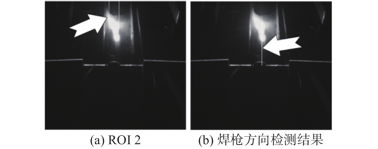
摘要: 针对基于激光视觉传感的镀锌钢薄板搭接GMAW特点,提出了一种搭接接头焊缝成形全位置特征与焊枪方向同步实时检测方法. 该方法利用激光视觉系统同步检测焊缝与焊丝信息,采用尺度不变特征变换与方向特征检测算法,同步实时获取焊缝轮廓与焊丝方向;采用Harris角点检测算法实现焊缝轮廓特征点识别;针对接头焊缝面积偏小的特点,采用线性插值方法实现了焊缝高度与宽度的全位置、焊缝面积的亚像素级测量,并基于零、一阶矩实现了焊缝重心检测. 结果表明,该算法适应性强、测精度高,为基于焊枪姿态和焊接过程参数优化在线控制焊缝成形提供了依据.Abstract: This paper presented a method to synchronously detect all-position weld bead geometry and the welding torch in lap joint GMAW with galvanized sheets, in which laser vision sensing was used. In this method a laser was used to simultaneously detect the weld bead and the welding torch, and the scale-invariant feature transform algorithm and orientation feature detection algorithm were used to extract the weld profile as well as the welding torch. The feature points of the profile were identified with the Harris corner detection algorithm. Since the weld area is relatively small, a sub pixel level measurement method was proposed to obtain the all-position bead height, width and area. The Weld center of gravity was detected with the zero and first moment. Experimental results showed the strong adaptability and high accuracy of that this proposed method. It provides the possibility of adjusting the attitude of the welding torch and welding process parameters to control weld formation online.
-
0. 序言
在工件表面制备抗磨涂层是提高工件耐磨性的重要技术手段,而涂层的抗磨性取决于其化学成分和微观组织. 在涂层中添加增强相能够有效的提高涂层的耐磨性,因而成为研究的热点[1]. 目前,在涂层组织中作为增强相的颗粒主要有TiC,TiB2,TiN,NbC等,而颗粒的添加方式有外部添加和原位自生. 原位自生颗粒增强相因其具有界面干净、颗粒与基体结合力强、不容易脱落等优点,越来越引起研究者的重视[2-4]. 但原位自生颗粒增强相也存在着颗粒相团聚导致性能下降现象. 稀土具有改善组织、减少颗粒团聚的特性,能够提高材料的物理和化学性能,因而在冶金、铸造等领域应用广泛[5]. He和Feng等人[6-7]研究发现,在熔覆涂层中添加适量的稀土氧化物能有效的减少颗粒的团聚现象. Li等人[8]利用激光熔敷在Q235钢表面制备含有稀土CeO2的Co基熔覆层,试验结果表明,稀土CeO2含量为1.5%(质量分数)时,熔覆涂层耐磨性最佳;当稀土含量增加时,熔覆层耐磨性下降;Zhang等人[9]利用激光熔敷在Q235钢表面添加不同尺寸的CeO2的Ni基熔敷层,结果表明添加纳米CeO2熔覆层的硬度和耐磨性要高于添加微米CeO2的熔覆层. 文中利用氩弧熔覆技术,在原位自生TiC增强Ni基熔覆层中添加稀土Y2O3氧化物,探讨稀土Y2O3对熔覆层组织的影响规律,以提高熔覆层的性能.
1. 试验方法
1.1 涂层的制备
制备涂层选用的基体材料为热轧的16Mn钢,试样尺寸为100 mm×10 mm×10 mm,涂层材料选用的是Ni60A粉末(表1)、Ti粉、C粉、Y2O3粉末,涂层材料的成分配比见表2,粉末在研磨钵中研磨均匀. 采用丙酮对16Mn钢的表面进行去油处理,然后利用胶水作为粘结剂,将涂层粉末材料涂覆在预处理好的16Mn钢基材表面. 预制好涂层后,在100 ℃的RT3-15-9型电炉中烘干2 h. 采用氩弧熔覆方法制备熔覆涂层,氩弧熔覆利用MW3000型数字式焊机,熔覆工艺为:电流115 ~ 125 A,熔覆速度为3 mm/s,氩气流量10 L/min左右.
表 1 Ni60A自熔合金粉成分(质量分数,%)Table 1. Composition of Ni60A self-fluxing alloy powderCr Si B C Ni 7 ~ 18 3.5 ~ 5.5 3.0 ~ 4.5 0.5 ~ 1.0 余量 表 2 熔覆材料成分配比(质量分数,%)Table 2. Composition proportion of clad materials成分 Ni60A Ti粉 C粉 Y2O3 1 80 16 4 − 2 79 16 4 1 3 78 16 4 2 4 77 16 4 3 1.2 涂层的微观组织表征
将熔覆试件沿垂直于涂层的方向进行切割后制备金相观察试件,涂层的微观组织形貌采用MX2600型扫描电子显微镜(SEM)观察,并用其附带的OXFORD能谱分析仪分析相成分、结合区与基体、结合区与熔敷区的界面元素分布;采用RigakuD/max2200型X射线衍射仪(XRD)扫描涂层表面,测定涂层的物相组成.
1.3 涂层的性能测试
利用MHV2000型显微硬度仪在金相试件上测量由涂层到基体的显微硬度分布. 在MMS-2B磨损试验机测试摩擦磨损性能,试验参数为:磨损试验力为200 N,对磨环转速为200 r/min,磨损时间为40 min.
2. 结果与分析
2.1 涂层的物相组成和组织形态分析
原位自生TiC增强Ni基熔覆涂层的宏观形貌见图1所示,涂层与基体的截面能谱扫描如2所示,由图1和图2可以看出,涂层与基体之间的结合处无气孔、裂纹等缺陷,同时涂层与基体之间发生了Ti,Ni,Fe等元素的相互扩散,涂层与基体之间实现了冶金结合.
Ni60A粉末、Ti粉、C粉在电弧高温的作用下可以生成多种化合物相,运用“无机热化学数据库(ITDB)”进行热力学数据检索和系列热力学计算结果如图3所示. 由图3可知,反应生成自由能小于TiC自由能的各相有Cr23C6,TiB2,Cr7C3,Cr5Si3,Ni4B等.
对未加稀土Y2O3和添加2%稀土Y2O3的熔覆涂层的物相分析结果如图4所示. 两种复合涂层的物相均为γ-Ni,Cr23C6和TiC相,添加Y2O3后并没有新相生成. TiC相的存在说明氩弧熔覆过程中C和Ti元素原位反应生成了TiC. Ni60A合金粉中Cr含量较高,而且Cr23C6的反应生成自由能最低,所以很容易生成Cr23C6. 由于涂层材料中B,Si元素的含量较低,且反应生成自由能相对较高,在涂层中形成的含B,Si元素的化合物相的量很少,未被X-ray检测到. 虽然添加Y2O3后并没有新相生成,但是衍射峰值有所变化,添加稀土Y2O3后TiC和Cr23C6峰值有所增加,主要原因为稀土Y2O3促进形核所致.
为确定涂层的微观组织,将添加2%Y2O3的熔覆涂层局部放大并进行能谱分析,如图5所示. 由图5可知,涂层的微观组织由黑色颗粒相(B)、灰色块状相(C)、黑白相间的网状组织(D)组成,部分黑色颗粒相中还存在白色的点状物(A). 不同物相的成分能谱分析的结果见表3. 结合物相分析黑色颗粒相为TiC,黑色颗粒中间的白色点为稀土Y,灰色块状相为γ-Ni基体,基体之间分布的网状为γ-Ni与Cr23C6共晶产物[10]. 从图可以看出,熔覆涂层的合金体系的组织形态为亚共晶组织形貌,先结晶相呈黑色形态. 随着结晶温度的降低,发生共晶反应生成灰白色基体上分布着黑色颗粒状的共晶组织.
表 3 不同位置颗粒相成分(质量分数,%)Table 3. Tab2 Composition of the particles phase in the coating位置 C Si Y Ti Cr Fe Ni A 28.45 2.02 33.24 30.19 1.84 3.07 1.20 B 27.22 0.93 2.15 62.31 2.39 3.71 1.30 C 5.73 1.35 − 0.82 3.66 15.81 72.64 D 5.94 0.50 − 1.08 10.38 5.78 76.32 2.2 Y2O3对涂层微观组织的影响
图6为不同稀土含量熔覆涂层的背散射组织形貌. 从图中可以看出,加入Y2O3后,涂层的组织形貌明显改善,Y2O3加入后,氩弧熔覆层中的TiC陶瓷相细小、分布较均匀. 相比而言,含2% Y2O3的涂层组织最为细小,硬质相TiC含量最多. 分析认为,氩弧熔覆凝固过程中,Y2O3的加入,改变了固液界面前沿的浓度分布,造成严重的成分过冷,进而改变了固液前沿的温度梯度,形成近枝晶形态的γ-Ni相. 同时Y2O3也会改变固态的熔点,在枝晶处富集的稀土会降低固溶体熔点,使枝晶熔断,在凝固过程中成为新的晶核而长大,从而细化晶粒. 另外,稀土元素在基体中的固溶度较小,化学活性较强,容易与Ni60A中的B,Si等元素发生化学反应形成稳定的化合物,增加熔覆层中TiC的形核质点,提高形核率,从而细化晶粒使其呈等轴状(图6c). 同时稀土元素对碳化物长大过程中相界面起到钉扎作用,阻碍其长大;稀土还会降低界面张力,减少晶粒长大的驱动力,导致晶粒长大速度减慢,从而也细化组织[11]. 但当Y2O3含量的添加量为3%时,熔覆涂层的组织形貌反而变差,TiC颗粒含量减少并出现团聚现象. 分析原因认为Y2O3加入过量时,稀土偏聚在TiC颗粒界面处,降低合金系的熔点[11],在氩弧加热条件下,稀土偏聚处会加速TiC颗粒表面的熔化和分解,造成TiC颗粒烧损(图6d),颗粒相的含量减少. 同时,稀土过量后TiC颗粒与基体界面过冷度会小,根据凝固理论,过冷度小,形核率小,长大速度快,所以TiC颗粒尺寸增大. TiC的生长基元为八面体,长大方式为棱边连接或顶角连接,在温度高即过冷度较小的条件下,晶体以二维形核方式长大会降低其表面能,所以TiC颗粒出现棱边连接或顶角连接长大,即团聚现象.
2.3 Y2O3对涂层性能的影响
图7为不同成分氩弧熔覆涂层从涂层到基体的显微硬度分布曲线. 由图可见,熔覆涂层的显微硬度最高,沿基体方向呈阶梯状递减,熔覆涂层显微硬度较基体提高3 ~ 7倍. 熔覆涂层之所以具有较高的显微硬度,首先是因为具有较高硬度的TiC陶瓷颗粒均匀而细小的分布在熔覆层中,其次是作为熔覆层基体的镍基固溶了大量的合金元素,起到明显的固溶强化作用. 由硬度分布曲线来看,距表面0 ~ 1.5 mm范围内的熔覆涂层具有较高的硬度,过渡区域在距涂层表面1.8 ~ 2.0 mm处. 从图中可以明显的看出Y2O3的加入量不同,涂层的硬度提高的程度亦不同. Y2O3含量2%的涂层硬度最高,硬度值大概为基体的4倍左右,也表现出优异的耐磨性能(如图8所示,磨损量最小). 涂层表现出的较高硬度及优异的耐磨性能主要与其中分布均匀而致密的TiC有关. 结合组织分析(图6)可以看出,加入Y2O3后涂层的组织细化,颗粒相含量有所增加,添加1%Y2O3的涂层中,颗粒相尺寸和含量明显优于没有添加Y2O3的涂层. 添加2%Y2O3的熔覆涂层的组织相比添加1%Y2O3的熔覆涂层组织更为细小,加之原位自生颗粒TiC与基体界面结合更为牢固,在摩擦磨损过程中不容易脱落,起到良好的支撑和耐磨作用,所以这两种涂层具有较高的硬度和耐磨性,添加2%Y2O3熔覆涂层的耐磨性较未添加Y2O3涂层提高0.5倍,较基体提高11倍. 但当添加3% Y2O3时,涂层的硬度值和耐磨性较未添加Y2O3的熔覆涂层有所降低,耐磨性较未添加Y2O3的熔覆涂层降低1.2倍,较基体提高2.6倍,主要原因为过多的稀土会降低氩弧熔覆熔池中液态合金的流动性,导致熔池中液体金属对流速度减慢,而且稀土较多时TiC颗粒大量烧损,颗粒相含量降低,并且TiC颗粒发生团聚现象(图6d),导致熔覆涂层表面硬度和耐磨性较未添加稀土熔覆涂层的有所降低.
3. 结论
(1) 原位自生TiC增强Ni基涂层的微观组织由TiC颗粒相、Ni基固溶体、γ-Ni与Cr23C6共晶相组成,添加Y2O3没有改变熔覆涂层中的物相组成.
(2) 在涂层材料中添加2%Y2O3能够使涂层组织细化、TiC颗粒分布均匀;过量的Y2O3使TiC颗粒团聚.
(3) 涂层材料中添加2%Y2O3,熔覆涂层具有较高的显微硬度,并且耐磨性能优异.
-
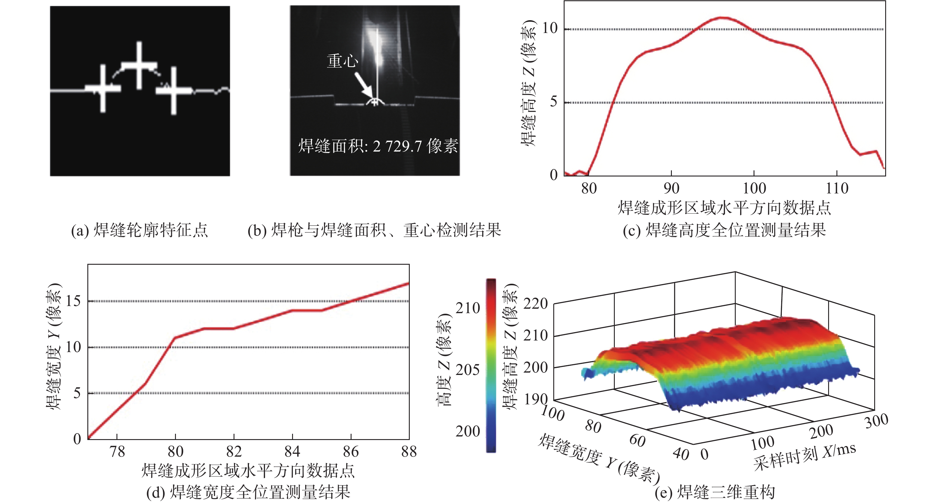
图 9 焊缝特征检测结果
Figure 9. Weld feature detection results. (a) feature points of the weld profile; (b) detection results of the welding torch, weld area and the center of gravity; (c) all position measurement result of the weld height; (d) all position measurement result of the weld width; (e) 3D reconstruction of the weld
-
[1] Jahanzaib M, Hussain S, Wasim A, et al. Modeling of weld bead geometry on HSLA steel using response surface methodology[J]. The International Journal of Advanced Manufacturing Technology, 2017, 89(5): 2087 − 2098.
[2] Neelamegam C, Sapineni V, Muthukumaran V, et al. Hybrid intelligent modeling for optimizing welding process parameters for reduced activation ferritic-martensitic (RAFM) steel[J]. Journal of Intelligent Learning Systems and Applications, 2013, 5(1): 39 − 47.
[3] Om H, Pandey S. Effect of heat input on dilution and heat affected zone in submerged arc welding process[J]. Sadhana, 2013, 38(6): 1369 − 1391. doi: 10.1007/s12046-013-0182-9
[4] Chen C, Fan C, Cai X, et al. Investigation of formation and microstructure of Ti-6Al-4V weld bead during pulse ultrasound assisted TIG welding[J]. Journal of Manufacturing Processes, 2019, 46: 241 − 247. doi: 10.1016/j.jmapro.2019.09.014
[5] Xiong J, Zhang G. Online measurement of bead geometry in GMAW-based additive manufacturing using passive vision[J]. Measurement Science and Technology, 2013, 24(11): 115103. doi: 10.1088/0957-0233/24/11/115103
[6] He Y, Li D, Pan Z, et al. Dynamic modeling of weld bead geometry features in thick plate GMAW based on machine vision and learning[J]. Sensors, 2020, 20(24): 7104 − 7122. doi: 10.3390/s20247104
[7] Yang L, Fan J, Liu Y, et al. Automatic detection and location of weld beads with deep convolutional neural networks[J]. IEEE Transactions on Instrumentation and Measurement, 2021, 70: 1 − 12.
[8] Xiao Jun, Wen Tao, Chen Shujun, et al. Teleoperation strategies research for collaborative welding systems based on virtual reality[J]. China Welding, 2020, 29(2): 38 − 47.
[9] Kalwasiński D. The position for experimental research to simulate sense of touch[J]. Mechanik, 2016, 89(7): 718 − 720.
[10] 潘海鸿, 尹华壬, 梁旭斌, 等. 可调整焊枪姿态直线摆弧路径算法研究[J]. 组合机床与自动化加工技术, 2019, 11: 37 − 41. Pan Haihong, Yin Huaren, Liang Xubin, et al. Research on the algorithm of linear swing arc path with adjustable welding torch attitude[J]. Modular Machine Tool & Automatic Manufacturing Technique, 2019, 11: 37 − 41.
[11] 余卓骅, 胡艳梅, 何银水. 薄板机器人自动焊接焊枪三维偏差的有效提取[J]. 焊接学报, 2019, 40(11): 49 − 53. doi: 10.12073/j.hjxb.2019400287 Yu Zhuohua, Hu Yanmei, He Yinshui. Effective three-dimensional deviation extraction of the welding torch for robotic arc welding with steel sheets[J]. Transactions of the China Welding Institution, 2019, 40(11): 49 − 53. doi: 10.12073/j.hjxb.2019400287
[12] Lowe D G. Distinctive image features from scale-invariant keypoints[J]. International Journal of Computer Vision, 2004, 60(2): 91 − 110. doi: 10.1023/B:VISI.0000029664.99615.94
-
期刊类型引用(2)
1. 王永东,王金宇,常萌阳. Y_2O_3对原位自生TiC-TiB_2增强镍基复合涂层组织与性能的影响. 黑龙江科技大学学报. 2024(02): 230-236 .  百度学术
百度学术
2. 张宇鹏,王永东,徐刚,宫书林,汤明日,王磊. 石墨烯对激光熔覆Ti-C-Nb增强Ni基涂层组织与性能的影响. 激光与光电子学进展. 2022(01): 208-216 .  百度学术
百度学术
其他类型引用(1)


 下载:
下载:


