
Analysis of CMT Advanced+P welding-brazing characteristics of 7075/TC4 dissimilar metals
-
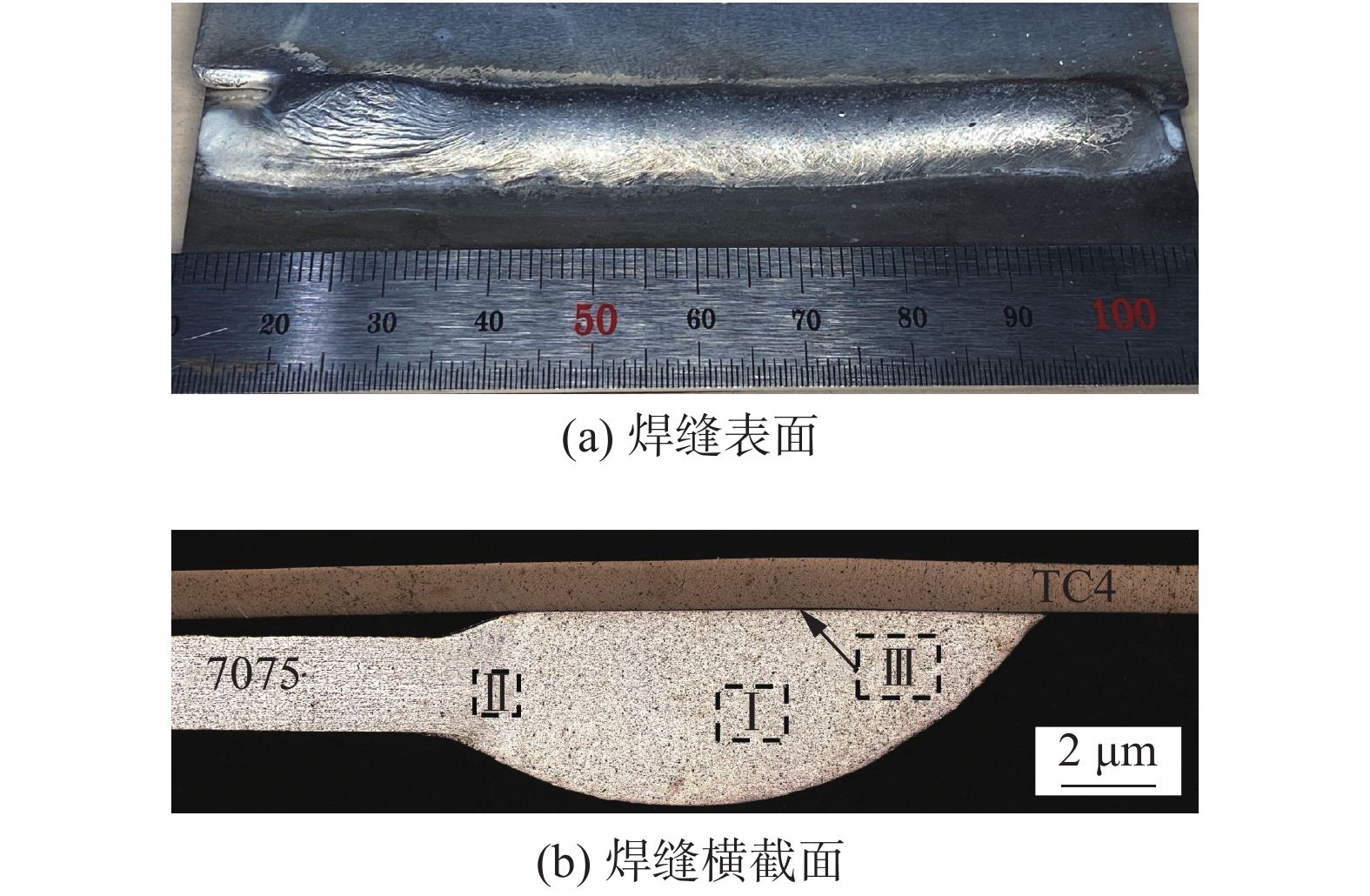
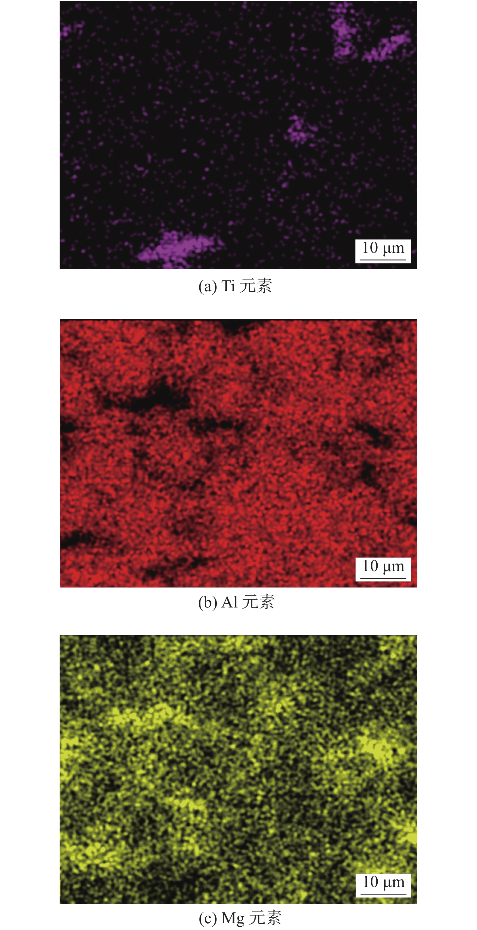
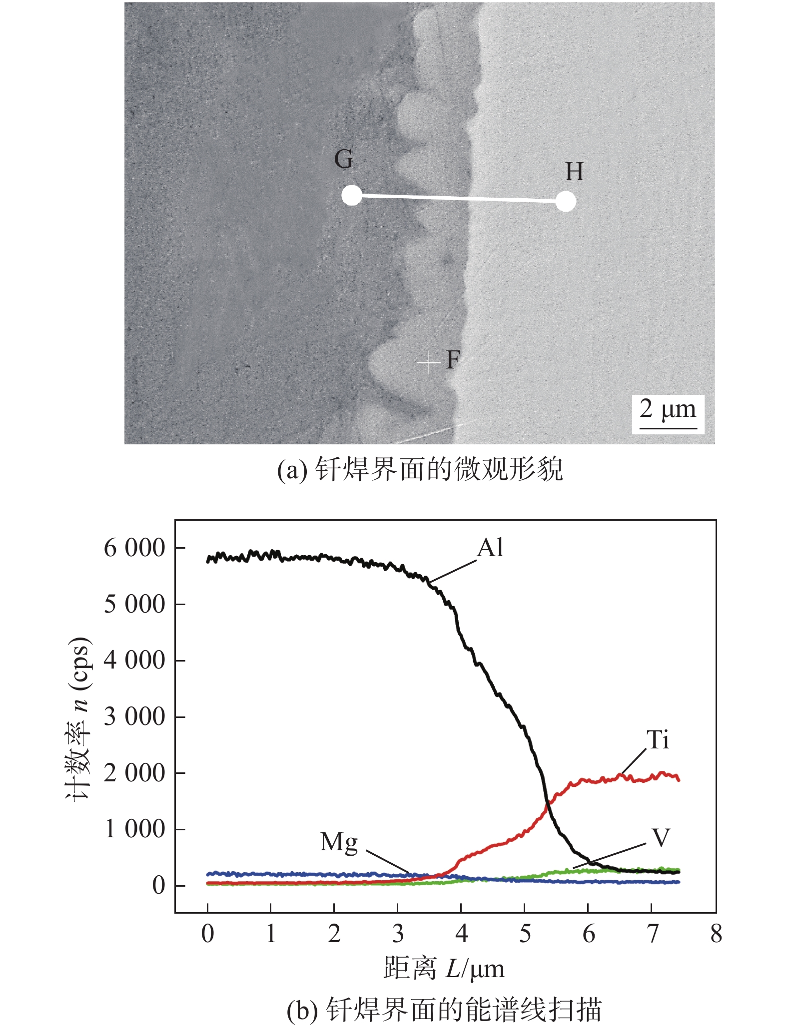
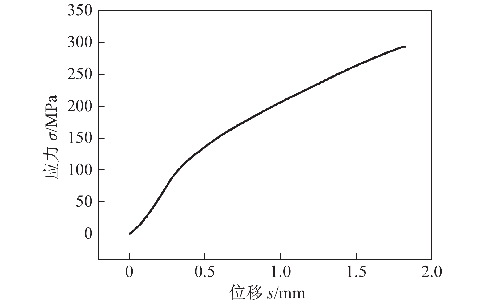
摘要: 基于CMT Advanced+P焊接方法,以ER5356铝合金焊丝对7075铝合金和TC4钛合金组成的搭接接头进行熔钎焊试验,并对接头进行微观组织及力学性能分析. 结果表明,焊接接头主要由焊缝区、铝合金侧热影响区和钎焊界面区组成;焊缝区主要是等轴晶;铝合金侧热影响区的晶粒表现出轧制特性,并在晶界附近析出大量金属间化合物;钎焊界面区存在由钛侧向焊缝区进行生长的锯齿状金属间化合物层,该化合物层厚度1 ~ 2.5 μm,主要由Al-Ti金属间化合物组成;接头拉伸后断裂位置位于铝合金侧热影响区附近,断裂类型属于混合断裂,最高抗剪强度达到293.1 MPa.Abstract: Based on CMT advanced + P welding method, the welding-brazing test of 7075 aluminum alloy and TC4 titanium alloy lap joint was carried out using ER5356 filler metal. The microstructure and mechanical properties of the joint were analyzed. The results showed that the welded joint was composed of weld zone, heat affected zone and brazing interface zone. The weld zone was mainly composed of equiaxed grains. The grains in the heat affected zone of aluminum alloy showed rolling characteristics, and a certain amount of intermetallic compounds were precipitated near the grain boundary. In the brazing interface area, there existed a serration-shaped intermetallic compound layer growing from the lateral weld area of titanium. The thickness of the compound layer was 1 ~ 2.5 μm and mainly composed of Al-Ti intermetallic compounds. The fracture location of the joint was near the heat affected zone of the aluminum alloy, and the tensile fracture type was mixed fracture, with the maximum shear strength of 293.1 MPa.
-
Keywords:
- aluminum alloy /
- titanium alloy /
- cold metal transfer /
- welding-brazing
-
0. 序言
管道插接形成的相贯线焊缝在航天航空、石油化工、建筑、船舶等工程领域广泛存在,是一种典型的焊缝形式[1]. 但管管相贯结构所形成的焊缝为空间曲线焊缝,坡口形状不规则且有不均匀的变化[2]. 为实现其焊接自动化,国内外学者进行了大量的研究工作. 早期的管管焊接设备的研究主要是针对大型的管道对接焊接,通过使用周向运动的焊接小车,环绕焊缝运动实现大型管道的相贯线焊接[3]. 或者采用分段的方式将圆周焊道细分为小段,再平滑过渡分段函数拟合为连续函数[4],以此来研究管道对接全位置焊接. 康少杰等人[5]开发了一种可变式圆弧轨道的焊接机器人装置,能进行相贯线焊缝全方位不同宽度焊缝的焊接. 随着管管焊接的需求趋于复杂化、差异化,管管焊接设备的研究也朝着精细化智能化发展. 高利军等人[6]设计了一种新型钢制暖气片相贯线焊缝专用焊机,并建立了相贯线焊缝数学模型,推导出了基于此模型的焊机自步角算法. 刘永滨等人[7]则采用MSC.Marc软件对天然气管道在役修补焊接过程进行数值模拟,其管道残余变形峰值出现在焊缝的收弧区域,最大收缩变形量为1.79 mm. 上述关于管道插接的相贯线焊接的研究,多是针对于单一管道或者同一类型的多个不同管道插接焊缝,对于同时需要焊接两个及以上不同直径乃至不同插接形式的焊接任务,相关研究并不多见.
针对筒体内壁的管道插接焊接任务,设计了一种能提取支管空间位置和尺寸信息的传感器,并在此基础上建立管道插接焊缝位置模型和焊缝特征与焊枪姿态矩阵,最后利用MATLAB结合初值对该数学模型进行了数值模拟验证.
1. 管道插接焊缝位置识别传感器
管道插接有管-板插接、管-管插接、管-锥插接和管-球插接等种类,其中每个种类有各种插接形式,例如管-管插接又包含有管管正交、管管斜交、管管正交偏置、管管斜交偏置4种形式,所以管道插接焊缝不仅曲线复杂,而且种类繁多. 然而,在大部分管道插接焊缝的焊接任务中,其主件(即主板、主管、锥体或球体)位置均为已知,只需确定支管位置及尺寸,便能得到焊缝位置.
如图1所示,焊缝位置识别传感器通过提取支管开口截面内圆的空间位置和尺寸(即图1a加粗的空间圆),来确定支管空间位置,提取方法为图1b所示通过传感器获取过支管开口截面内圆的同轴的两锥面A和 B,联立两锥面得到的空间圆即为支管开口截面内圆. 实际操作时,通过获取锥面A和锥面B上各4条相同方位的母线,取交点达到相同效果. 此传感器对于不同支管直径,不同管道插接种类和管道插接形式具有通用性. 焊缝位置识别传感器如图1c所示,由支架、曲柄、连杆、滑块、角度传感器和铰链底座组成,共含有4组曲柄滑块机构.
![]() 图 1 传感器识别目标、方法和三维模型Figure 1. Sensor identification target, identification and 3D model. (a) open section inner circle; (b) identification method; (c) sensor 3D model
图 1 传感器识别目标、方法和三维模型Figure 1. Sensor identification target, identification and 3D model. (a) open section inner circle; (b) identification method; (c) sensor 3D model如图2所示,当进行采样识别工作时,传感器整体沿支架轴线下降伸入支管内部,由于受支管对曲柄的反作力,4组曲柄滑块机构将分别运动到某一位置,此时进行第一次采样,由4个角度传感器获取此时曲柄对支架的夹角,由编码器反馈此时传感器高度,每组曲柄滑块的位置和角度信息可以得到一条空间直线;采集完毕后,传感器继续下降一定位置,进行第二次采样. 将第二次采样得到的空间直线与第一次采样得到的空间直线联立,可以得到4个交点,所得的交点均在支管开口截面内圆上. 空间上三点可确定空间圆的尺寸与位置,第4点用来防止干扰点与减小误差.
![]() 图 2 传感器信号采集Figure 2. Sensor signal acquisition. (a) first sampling; (b) second sampling
图 2 传感器信号采集Figure 2. Sensor signal acquisition. (a) first sampling; (b) second sampling2. 管道插接焊缝的数学模型
以圆筒内壁的管道插接为研究对象,包含管管正交、管管斜交、管管正交偏置、管管斜交偏置等插接形式,建立基于焊缝位置识别传感器的焊缝数学模型,及焊缝焊枪特征矩阵. 如图3所示,传感器增加小车支架、小车移动副、转盘转动副、电动缸移动副,并移动到图3所示的初始位置,以转盘转动副轴线与传感器支架轴线交点为原点O1,重力方向为z1轴,圆筒轴线方向为x1轴,建立O1x1y1z1初始坐标系,其中小车移动副的移动方向与x1轴方向重合,转盘轴线方向与x1轴重合,在初始位置传感器轴线与z1轴重合.
2.1 管道插接焊缝位置模型
如图4所示,小车从初始位置沿x1轴方向平移
$ l $ ,转盘以x1轴为轴线顺时针旋转$\alpha $ 角,得到O2x2y2z2工作坐标系,则坐标系O1x1y1z1到坐标系O2x2y2z2的变换矩阵.$$ {}_2^1T = \left[ {\begin{array}{*{20}{c}} 1&0&0&l \\ 0&{\cos \alpha }&{ - \sin \alpha }&0 \\ 0&{\sin \alpha }&{\cos \alpha }&0 \\ 0&0&0&1 \end{array}} \right] $$ (1) 圆筒内壁半径为R,轴线在x1O1z1面内,与x1轴平行且距离为
$ {l_0} $ . 圆筒内壁在坐标系O2x2y2z2下的方程为$$ {(y + {l_0}\sin \alpha )^2} + {({\textit{z}} - {l_0}\cos \alpha )^2} = {R^2} $$ (2) 在O2x2y2z2坐标系下,已知传感器铰链底座的4个铰链轴线所在平面到x2O2y2面距离为Z0,4组曲柄的方位角为
$$ {\phi _i} = \left\{ \begin{gathered} 0,\;i = 1 \\ \frac{1}{2}{\text{π}} ,\;i = 2 \\ {\text{π}} ,\;i = 3 \\ \frac{3}{2}{\text{π}} ,\;i = 4 \\ \end{gathered} \right. $$ (3) 第一次采样得到的直线参数方程为
$$ \left\{ \begin{gathered}p_i =(x_i,y_i,z_i,) \\ x = (t + {r_{\rm{0}}}) \cos {\phi _i} \\ y = (t + {r_{\rm{0}}}) \sin {\phi _i} \\ {\textit{z}} = - t \cot {\beta _{1i}}+ {Z_0} + {Z_1} \\ \end{gathered} \right. ,\;i=1,2,3,4 $$ (4) 第二次采样得到的直线参数方程为
$$ \left\{ \begin{gathered} x = (t + {r_{\rm{0}}}) \cos {\phi _i} \\ y = (t + {r_{\rm{0}}}) \sin {\phi _i} \\ {\textit{z}} = - t \cot {\beta _{2i}} + {Z_0} + {Z_1} + {Z_2} \\ \end{gathered} \right. $$ (5) 式中:
$ {r_0} $ 为铰链轴线到支架轴线距离;$ {\beta _{1i}} $ ,$ {\beta _{2i}} $ 分别为第一次采样和第二次采样得到的曲柄与传感器轴线夹角的角度数据;$ {Z_1} $ 为第一次采样时电动缸移动距离;$ {Z_2} $ 为第一次采样移动到第二次采样时电动缸移动距离,联立(4)和(5),可得$$ {t_i} = \frac{{{Z_2}}}{{\cot {\beta _{2i}} - \cot {\beta _{1i}}}},\;i = 1,2,3,4 $$ (6) 代入式(4)得到两组直线的4个交点,此4点即为支管开口截面内圆上4点,设
$ {P_i} = ({x_i},{y_i},{z_i}), i = 1,2,3,4 $ ,则$$ \left\{ \begin{gathered} {x_i} = ({t_i} + {r_{\rm{0}}}) \cos {\phi _i} \\ {y_i} = ({t_i} + {r_{\rm{0}}}) \sin {\phi _i} \\ {{\textit{z}}_i} = - {t_i} \cot {\beta _{1i}} + {Z_0} + {Z_1} \\ \end{gathered} \right. ,\;i = 1,2,3,4 $$ (7) 取支管开口截面内圆所在平面内的两个向量为
$$ \left\{\begin{gathered} {{ {{\boldsymbol{n_1}}}}} = {P_1} - {P_2} = ({x_1} - {x_2},{y_1} - {y_2},{{\textit{z}}_1} - {{\textit{z}}_2}) \\ {{ {{\boldsymbol{n_2}}}}} = {P_1} - {P_3} = ({x_1} - {x_3},{y_1} - {y_3},{{\textit{z}}_1} - {{\textit{z}}_3}) \\ \end{gathered} \right.$$ (8) 则支管开口截面内圆所在平面的法向量为
$$ \left\{ \begin{gathered} {\boldsymbol{n}} = { {\boldsymbol{n_1}}} \times { {\boldsymbol{n_2}}} = ({{{x}}_{ {{n}}}},{{{y}}_{ {{n}}}},{{{{{{{\textit{z}}}}}}}_{ {{n}}}}) \\ {{{x}}_{ {{n}}}} = \left| {\begin{array}{*{20}{c}} {{y_1} - {y_2}}&{{{\textit{z}}_1} - {{\textit{z}}_2}} \\ {{y_1} - {y_3}}&{{{\textit{z}}_1} - {{\textit{z}}_3}} \end{array}} \right| \\{{{y}}_{ {{n}}}} = \left| {\begin{array}{*{20}{c}} {{{\textit{z}}_1} - {{\textit{z}}_2}}&{{x_1} - {x_2}} \\ {{{\textit{z}}_1} - {{\textit{z}}_3}}&{{x_1} - {x_3}} \end{array}} \right| \\{{{{\textit{z}}}}_{ {{n}}}} = \left| {\begin{array}{*{20}{c}} {{x_1} - {x_2}}&{{y_1} - {y_2}} \\ {{x_1} - {x_3}}&{{y_1} - {y_3}} \end{array}} \right| \end{gathered}\right.$$ (9) 直线
$ {l_{{P_1}{P_2}}} $ 、直线$ {l_{{P_1}{P_3}}} $ 的中点坐标为$$ \left\{\begin{gathered} {P_{12}} = \frac{{{P_1} + {P_2}}}{2} = ({x_{{P_{12}}}} , {y_{{P_{12}}}} ,{{\textit{z}}_{{P_{12}}}}) = \left(\frac{{{x_1} + {x_2}}}{2} , \frac{{{y_1} + {y_2}}}{2} , \frac{{{{\textit{z}}_1} + {{\textit{z}}_2}}}{2}\right) \\ {P_{13}} = \frac{{{P_1} + {P_3}}}{2} = ({x_{{P_{13}}}} , {y_{P_{13}}} ,{{\textit{z}}_{{P_{13}}}}) = \left(\frac{{{x_1} + {x_3}}}{2} , \frac{{{y_1} + {y_3}}}{2} , \frac{{{{\textit{z}}_1} + {{\textit{z}}_3}}}{2}\right) \\ \end{gathered} \right.$$ (10) 直线
$ {l_{{P_1}{P_2}}} $ 、直线$ {l_{{P_1}{P_3}}} $ 的中垂线方向向量为$$ \left\{\begin{gathered} {{ {{\boldsymbol{n_{{\boldsymbol{12}}}}}}}} = {\boldsymbol{ n}} \times {{ {\boldsymbol{n_1}}}} =\left(x_{12}, y_{12}, {\textit{z}}_{12}\right) \\ {{ {{\boldsymbol{n_{{\boldsymbol{13}}}}}}}} = {\boldsymbol{n}} \times {{ {\boldsymbol{n_2}}}} =\left(x_{13}, y_{13}, {\textit{z}}_{13}\right) \\ \end{gathered}\right. $$ (11) 由于直线
$ {l_{12}} $ 与直线$ {l_{13}} $ 的中垂线都经过空间圆的圆心c,有$P_c=\left(x_c, y_c, {\textit{z}}_c\right)$ ,即$$ {P_{12}} + {\lambda _1}{ {{\boldsymbol{n_{{\boldsymbol{12}}}}}}} = {P_{13}} + {\lambda _2}{ {{\boldsymbol{n_{{\boldsymbol{13}}}}}}} $$ (12) $$ \left\{\begin{array}{l} x_{P_{12}} + \lambda_1 x_{ 12}=x_{P_{13}} + \lambda_2 x_{ 13} \\ y_{P_{12}} + \lambda_1 y_{12}=y_{P_{13}} + \lambda_2 y_{13} \end{array}\right. $$ (13) $$ \lambda_2=\frac{\left(y_{P_{12}}-y_{P_{13}}\right) x_{ {12}}-\left(x_{P_{12}}-x_{P_{13}}\right) y_{ 12}}{y_{P_{13}} x_{P_{12}}-y_{P_{12}} x_{P_{13}}} $$ (14) $$ ({x_c},{y_c},{{\textit{z}}_c}) = {P_{13}} + {\lambda _2}{ {{\boldsymbol{n_{{\boldsymbol{13}}}}}}} $$ (15) 由距离公式得半径r为
$$ r = \left| {{P_1} - {P_c}} \right| = \sqrt {{{({x_1} - {x_c})}^2} + {{({y_1} - {y_c})}^2} + {{({{\textit{z}}_1} - {\textit{z}_c})}^2}} $$ (16) 设x2轴单位矢量为
$ {\boldsymbol{i}} = (1,0,0) $ ,支管开口截面与y2O2z2面的交线的单位矢量为$ {\boldsymbol{a}} $ ,则$$ \left\{\begin{array}{l} {\boldsymbol{a}} = \dfrac{{ {\boldsymbol{n}} \times ( - {\boldsymbol{i}})}}{{\left| { {\boldsymbol{n}} \times ( - {\boldsymbol{i}})} \right|}} =\left(x_a, y_a, {\textit{z}}_a\right) \\ {\boldsymbol{b }}= \dfrac{{ {\boldsymbol{n}} \times {\boldsymbol{a}}}}{{\left| { {\boldsymbol{n}} \times {\boldsymbol{a}}} \right|}}=\left(x_b, y_b, {\textit{z}}_b\right) \end{array}\right. $$ (17) 由圆心
$ c $ 、圆上正交单位矢量$ {\boldsymbol{a}}$ 和$ {\boldsymbol{b}}$ 、半径r可得空间圆参数方程.$$ \left\{\begin{array}{l} x=x_c + r x_{ {{{a}}}} \cos \theta\, + r x_{ {{{b}}}} \sin \theta \\ y\,=y_c + r y_{ {{{a}}}} \cos \theta \,+ r y_{ {{{b}}}} \sin \theta \\ {\textit{z}}\,=\,{\textit{z}}_c + r {\textit{z}}_{ {{{a}}}} \cos \theta\, + r {\textit{z}}_{ {{{b}}}} \sin \theta \end{array}\right.$$ (18) 式(18)为支管开口截面内圆所在空间位置方程,参数
$ \theta $ 取值范围为$ [0,\;2{\text{π}} ] $ ,此时参数$ \theta $ 的物理意义为圆上一点到圆心c连成的直线与$ {\boldsymbol{a}}$ 的夹角.支管内壁曲面参数方程为
$$ \left\{\begin{array}{l} x^{\prime}=x-\lambda x_{ {{n}}} \\ y^{\prime}=y-\lambda y_{ {{n}}} \\ {\textit{z}}^{\prime}={\textit{z}}-\lambda {\textit{z}}_{ {{n}}} \end{array}\right. $$ (19) $$ \left\{\begin{array}{l} x^{\prime} = x_c + r x_{ {{{a}}}} \cos \theta + r x_{ {{{b}}}} \sin \theta - \lambda x_{ {{{n}}}} \\ y^{\prime}= y_c + r y_{ {{{a}}}} \cos \theta \,+ r y_{ {{{b}}}} \sin \theta - \lambda y_{ {{{n}}}} \\ \,{\textit{z}}^{\prime} ={\textit{z}}_c + r {\textit{z}}_{ {{{a}}}} \cos \theta \,+ r {\textit{z}}_{ {{{b}}}} \sin \theta- \lambda {\textit{z}}_{ {{{n}}}} \end{array}\right. $$ (20) 式中:x,y,z为空间圆参数方程联立支管内壁曲面参数方程与主管方程.
$$ y^{\prime 2} + {\textit{z}}^{\prime 2}=R^2 $$ (21) $$ \lambda_\theta=\frac{\sqrt{R^2 y_{ {{n}}}^2 + R^2 {\textit{z}}_{ {{n}}}^2-{\textit{z}}^2 y_{ {{n}}}^2-y^2 {\textit{z}}_{ {{n}}}^2 + 2 y {\textit{z}} y_{ {{n}}} {\textit{z}}_{ {{n}}}}-y y_{ {{n}}} + {\textit{z}} {\textit{z}}_{ {{n}}}}{y_{ {{n}}}^2 + {\textit{z}}_{ {{n}}}^2} $$ (22) 带入(20)得到焊缝方程,即
$$ \left\{\begin{array}{l} x=x_c + r x_{ {{{a}}}} \cos \theta + r x_{ {{{b}}}} \sin \theta-\lambda_\theta x_{ {{{n}}}} \\ y\,=y_c + r y_{ {{{a}}}} \cos \theta \,+ r y_{ {{{b}}}} \sin \theta-\lambda_\theta y_{ {{{n}}}} \\ \,{\textit{z}}=\,{\textit{z}}_c + r {\textit{z}}_{ {{{a}}}} \cos \theta \,+ r {\textit{z}}_{ {{{b}}}} \sin \theta\,-\lambda_\theta {\textit{z}}_{ {{{n}}}} \end{array}\right. $$ (23) 2.2 管道插接焊缝特征模型
焊缝坐标系及焊缝辅助坐标系的定义参照文献[4],如图5所示,焊缝方程为关于
$ \theta $ 的参数方程,取$ \theta = {\theta _w} $ ,有焊缝上一点$ {P_w}({x_0},{y_0},{z_0}) $ ,空间圆上一点$ P_w^{'|}(x{'_w},y{'_w},z{'_w}) $ ,设$ {P_w} $ 点为当前焊点,则圆筒内壁在该焊点处的切平面A的法向量,即$$ { {{\boldsymbol{S}}_{ \boldsymbol{1}}}} = ({X_1},{Y_1},{Z_1}) = (0,{y_w} + {l_0}\sin \alpha ,{{\textit{z}}_w} - {l_0}\cos \alpha ) $$ (24) 支管在焊点处的切平面B的法向量为
$$ {{ {\boldsymbol{S}}_{ \boldsymbol{2}}}} = ({X_2},{Y_2},{Z_2}) = (x{'_w} - {x_c},y{'_w} - {x_c},{\textit{z}}{'_w} - {{\textit{z}}_c}) $$ (25) 平面A和平面B的夹角为二面角
$ \varphi $ ,即$$ \cos ( {{ {\boldsymbol{S}}_{ \boldsymbol{1}}}},{ {{\boldsymbol{S}}_{ \boldsymbol{2}}}}) = \frac{{{{{{\boldsymbol{S}}_{ \boldsymbol{1}}}}} \cdot {{ {{\boldsymbol{S}}_{ \boldsymbol{2}}}}}}}{{\left| {{{ {{\boldsymbol{S}}_{ \boldsymbol{1}}}}}} \right| \cdot \left| {{{ {{\boldsymbol{S}}_{ \boldsymbol{2}}}}}} \right|}} $$ (26) $$ \varphi = {\text{π}} - \arccos (\frac{{{{{{\boldsymbol{S}}_{ \boldsymbol{1}}}}} \cdot {{ {{\boldsymbol{S}}_{ \boldsymbol{2}}}}}}}{{\left| {{{{{\boldsymbol{S}}_{ \boldsymbol{1}}}}}} \right| \cdot \left| {{{ {{\boldsymbol{S}}_{ \boldsymbol{2}}}}}} \right|}}) $$ (27) 由于相贯线上任意点的切线,始终与过该点的两个圆柱切平面的交线重合,因此XW(XW1)坐标轴向量为
$$ { {{\boldsymbol{S}}_{ \boldsymbol{3}}}} = { {{\boldsymbol{S}}_{ \boldsymbol{2}}}} \times { {{\boldsymbol{S}}_{ \boldsymbol{1}}}} = ({X_3},{Y_3},{Z_3}) $$ (28) ZW1 坐标轴向量为
$$ { {{\boldsymbol{S}}_{ \boldsymbol{4}}}} = {{{\boldsymbol{S}}_{ \boldsymbol{2}}}} \times {{{\boldsymbol{S}}_{ \boldsymbol{3}}}} = ({X_4},{Y_4},{Z_4}) $$ (29) YW1坐标轴的向量为
$$ {{{\boldsymbol{S}}_{ \boldsymbol{5}}}} = { {{\boldsymbol{S}}_{ \boldsymbol{4}}}} \times { {{\boldsymbol{S}}_{ \boldsymbol{3}}}} = ({X_5},{Y_5},{Z_5}) $$ (30) 坐标系O2x2y2z2到坐标系Ow1xW1yW1zW1变换矩阵为
$$ {\boldsymbol{{}_{{\boldsymbol{w1}}}^2T}} = \left[ {\begin{array}{*{20}{c}} {{X_3}}&{{X_4}}&{{X_5}}&{{x_0}} \\ {{Y_3}}&{{Y_4}}&{{Y_5}}&{{y_0}} \\ {{Z_3}}&{{Z_4}}&{{Z_5}}&{{{\textit{z}}_0}} \\ 0&0&0&1 \end{array}} \right] $$ (31) 坐标系Ow1xW1yW1zW1绕xW1轴顺时针旋转
$ \varphi /2 $ ,得焊缝坐标系OwxWyWzW,即$$ {\boldsymbol{{}_w^{{\boldsymbol{w1}}}T}} = \left[ {\begin{array}{*{20}{c}} 1&0&0&0 \\ 0&{\cos \dfrac{\varphi }{2}}&{ - \sin \dfrac{\varphi }{2}}&0 \\ 0&{\sin \dfrac{\varphi }{2}}&{\cos \dfrac{\varphi }{2}}&0 \\ 0&0&0&1 \end{array}} \right] $$ (32) 焊缝坐标系相对于初始坐标系的特征矩阵为
$$ {}_{\boldsymbol{w}}^{\boldsymbol{1}}{\boldsymbol{T}} ={}_{\boldsymbol{2}}^{\boldsymbol{1}}{{\boldsymbol{T}}}\;\;{\boldsymbol{{}_{{\boldsymbol{w1}}}^2T}}\;\; {\boldsymbol{{}_w^{{\boldsymbol{w1}}}T}} = \left[ {\begin{array}{*{20}{c}} 1&0&0&0 \\ 0&{\cos \dfrac{\varphi }{2}}&{ - \sin \dfrac{\varphi }{2}}&0 \\ 0&{\sin \dfrac{\varphi }{2}}&{\cos \dfrac{\varphi }{2}}&0 \\ 0&0&0&1 \end{array}} \right] $$ (33) 2.3 焊枪姿态模型
焊缝坐标系到焊枪坐标系为
$$ {}_{\boldsymbol{r}}^{\boldsymbol{w}} {\boldsymbol{T}}= \left[ {\begin{array}{*{20}{c}} {\cos \gamma \cos \beta + \sin \gamma \sin \beta \sin \alpha }&{ - \sin \gamma \cos \beta + \cos \gamma \sin \beta \sin \alpha }&{\sin \beta \cos \alpha }&{{p_{twx}}} \\ {\sin \gamma \cos \alpha }&{\cos \gamma \cos \alpha }&{ - \sin \alpha }&{{p_{twy}}} \\ { - \cos \gamma \sin \beta + \cos \beta \sin \alpha \sin \gamma }&{\sin \gamma \sin \beta + \cos \beta \sin \alpha \cos \gamma }&{\cos \beta \cos \alpha }&{{p_{tw{\textit{z}}}}} \\ 0&0&0&1 \end{array}} \right] $$ (34) 通过焊枪坐标系相对焊缝坐标系的位姿矩阵,可以用数学算法计算出焊枪的3个角.
$$ 设 \;\; {}_{\boldsymbol{r}}^{\boldsymbol{w}}{\boldsymbol{T}} = \left[ {\begin{array}{*{20}{c}} {{C_{00}}}&{{C_{01}}}&{{C_{02}}}&{{p_{twx}}} \\ {{C_{10}}}&{{C_{11}}}&{{C_{12}}}&{{p_{twy}}} \\ {{C_{20}}}&{{C_{21}}}&{{C_{22}}}&{{p_{tw{\textit{z}}}}} \\ 0&0&0&1 \end{array}} \right] $$ (35) 由式(34)和式(35)可得
$$ \left\{\begin{gathered} \alpha = - \arcsin {C_{12}} \\ \beta = a\tan 2({C_{02}},{C_{22}}) \\ \gamma = a\tan 2({C_{10}},{C_{11}}) \\ \end{gathered}\right. $$ (36) 3. 仿真试验
在Creo平台上搭建筒体内壁管管插接焊缝自动焊接机器人的三维模型,并模拟工作环境,采集传感器角度信息,将数据带入上述模型与算法当中,获得管管插接焊缝空间位置数学模型.利用MATLAB软件对数学模型进行仿真验证,并与设定的工件焊缝曲线进行对比分析.设定同一空间坐标点为起始点,以相同的比例将工件焊缝曲线和传感器得到的数据曲线划分为64等份,得到各点的坐标值,部分数据如表1所示.
表 1 实际坐标点与采样坐标点(mm)Table 1. Actual coordinate point and the sampling coordinate point实际坐标点 采样坐标点 X Y Z X Y Z 10.000
9.950
9.800
9.553
9.210
8.775
8.253
7.648
6.967
6.2160
0.998
1.986
2.955
3.894
4.794
5.646
6.442
7.173
7.8336.633
6.707
6.924
7.261
7.691
8.184
8.711
9.246
9.770
10.26410.000
10.033
9.800
9.536
9.227
8.789
8.217
7.631
6.994
6.2370
1.065
2.035
2.914
3.911
4.912
5.760
6.420
7.295
7.9566.633
6.666
7.097
7.440
7.884
8.267
8.750
9.289
9.671
10.237对全部64个坐标数据进行分析比较,可得标定坐标点与采样坐标点在x轴和y轴方向的误差较小,其最大值为0.12 mm,而z轴方向的偏差较大,所以主要分析z轴方向的误差. 图6为z轴方向的焊缝偏差图,最大的焊缝偏差为0.25 mm,其精度满足实际焊接精度要求.
图7为传感器识别曲线与工件焊缝曲线整体对比图. 从图7可以看到,虽然二者存在一定偏差,但是整体偏差不大,传感器数据曲线基本接近工件焊缝曲线,证明了传感器模型和焊缝轨迹算法的准确性.
基于ABB公司开发的机器人仿真软件RobotStudio为平台,建立ABB机器人仿真系统. 通过通讯的方式将传感器所采集的焊缝位置,作为机器人运动轨迹传输给仿真平台,结合焊缝姿态模型与焊枪姿态模型,由运动学逆解求出机械臂关节量,再把求得的变量带入运动学求正解,进行轨迹与姿态仿真.仿真结果如图8所示,焊枪的运动轨迹与焊缝的特征完全重合,焊枪运动姿态也始终位于焊点两切面的夹角平分线上,验证了传感器所建立的数学模型正确性.
4. 结论
(1) 设计了适用于筒体内壁的管-管、管-板、管-球和管-锥等管道插接焊缝任务的焊缝位置识别传感器,该传感器能识别管道插接焊缝的空间位置,具有很强的实用性,为管道插接焊接任务的智能化提供支持.
(2) 提出了基于此传感器的针对筒体内壁管-管插接焊接任务的焊缝位置计算方法,并给出了焊缝特征矩阵与焊枪姿态矩阵,利用MATLAB软件对该方法获得的管管插接焊缝空间位置数学模型进行仿真验证,标定坐标点与采样坐标点在x轴和y轴方向的误差最大值仅为0.12 mm,在z轴方向上最大的焊缝偏差为0.25 mm,其精度满足实际焊接精度要求,表明了该方法的有效性和准确性.
-
![]()
图 3 铝/钛搭接接头的宏观形貌
Figure 3. Appearance of the aluminum/titanium lap joint. (a) weld surface; (b) weld junction
![]()
图 4 搭接接头腐蚀后的微观形貌
Figure 4. Microstructure of lap joint after corrosion. (a) weld zone; (b) heat affected zone (HAZ)
![]()
图 5 搭接接头未腐蚀的微观形貌
Figure 5. Microstructure of lap joint without corrosion. (a) weld zone; (b) HAZ (low power); (c) HAZ (high power)
![]()
图 6 XRD分析结果
Figure 6. XRD results. (a) one position of weld zone; (b) another position of weld zone; (c) HAZ
![]()
图 7 焊缝区元素面分布
Figure 7. Distribution of elements in weld zone. (a) titanium; (b) aluminum; (c) magnesium
![]()
图 8 钎焊界面区的微观形貌及能谱线扫描
Figure 8. Microstructure and energy spectrum scanning of brazing interface zone. (a) microstructure of brazing interface; (b) EDS line scanning of brazing interface
![]()
图 9 焊接接头拉伸试验的应力—位移曲线
Figure 9. Displacement-stress curve of welded joint tensile specimen
![]()
图 10 拉伸试样断裂位置及断口形貌
Figure 10. Fracture location and fracture morphology of tensile specimen. (a) fracture location of joint; (b) microstructure of intergranular fracture; (c) microstructure of transgranular cracking
表 1 钛合金的化学成分含量(质量分数,%)
Table 1 Chemical composition of titanium alloy
Al V Fe C N O H Ti 6 4 < 0.3 < 0.08 < 0.05 < 0.2 < 0.015 余量  下载: 导出CSV
表 2 铝合金及焊丝的化学成分含量(质量分数,%)
Table 2 Chemical composition of aluminum alloy and welding wire
元素 Si Fe Cu Mn Mg Cr Zn Ti Al 7075 0.4 0.5 2.0 0.3 2.5 0.2 5.8 0.20 余量 ER5356 0.25 0.4 0.1 0.05 5 0.1 0.1 0.1 余量
下载: 导出CSV
表 3 焊接工艺参数
Table 3 Welding parameters
送丝速度
ν/(m·min−1)焊接速度
ν/(cm·min−1)EN-CMT与
P比例电弧电压
U/V焊接电流
I/A6 38 3∶5 13.8 96
下载: 导出CSV
表 4 EDS能谱分析(原子分数,%)
Table 4 EDS energy spectrum analysis
位置 Al Mg Zn Cu Ti 可能的生成相 A 95.05 5.71 0.25 0.00 0.00 α-Al固溶体 + 少量Al-Mg化合物 B 98.35 1.65 0.00 0.00 0.00 α-Al固溶体 C 71.02 0.61 0.10 0.00 28.26 TiAl3 + 少量TiAl D 66.76 22.30 5.07 5.88 0.00 α-Al固溶体 + CuZn + Al6CuMg4 + Al-Mg化合物 E 63.39 16.41 10.67 9.54 0.00 α-Al固溶体 + CuZn + Al6CuMg4 + MgZn2 +
Al-Mg化合物F 71.88 0.24 0.20 0.01 27.67 TiAl3相 + 少量TiAl相
下载: 导出CSV
-
[1] Sun Q J, Li J Z, Liu Y B, et al. Microstructural characterization and mechanical properties of Al/Ti joint welded by CMT method-Assisted hybrid magnetic field[J]. Materials & Design, 2017, 116(2): 316 − 324.
[2] 刘全明, 张朝晖, 刘世锋, 等. 钛合金在航空航天及武器装备领域的应用与发展[J]. 钢铁研究学报, 2015, 27(3): 1 − 4. Liu Quanming, Zhang Zhaohui, Liu Shifeng, et al. Application and development of titanium alloy in aerospace and military hardware[J]. Journal of Iron and Steel Research, 2015, 27(3): 1 − 4.
[3] 吴一雷, 李永伟, 强俊, 等. 超高强度铝合金的发展与应用[J]. 航空材料学报, 1994(1): 49 − 55. Wu Yilei, Li Yongwei, Qiang Jun, et al. Development and application of supper-high strength aluminum alloys[J]. Journal of Aeronautical Materials, 1994(1): 49 − 55.
[4] Zhang, X, Chen Y, Hu Z. Recent advances in the development of aerospace materials[J]. Progress in Aerospace Ences, 2018, 97(2): 22 − 34.
[5] 庄敏. C919用了哪些新材料[J]. 大飞机, 2017(8): 34 − 37. doi: 10.3969/j.issn.2095-3399.2017.08.007 Zhuang Min. What new materials are used in C919[J]. Jetliner, 2017(8): 34 − 37. doi: 10.3969/j.issn.2095-3399.2017.08.007
[6] Jiang S, Li S. Formation mechanism and growth law of diffusion solution zone between Al/Ti liquid/solid interface[J]. Rare Metal Materials & Engineering, 2011, 40(6): 983 − 986.
[7] Zhang Y, Huang J, Ye Z, et al. An investigation on butt joints of Ti6Al4V and 5A06 using MIG/TIG double-side arc welding-brazing[J]. Journal of Manufacturing Processes, 2017, 27(6): 221 − 225.
[8] Miao Y, Ma Z, Yang X, et al. Experimental study on microstructure and mechanical properties of AA6061/Ti-6Al-4V joints made by bypass-current MIG welding-brazing[J]. Journal of Materials Processing Technology, 2018, 260: 104 − 111. doi: 10.1016/j.jmatprotec.2018.05.019
[9] Rajakumar S, Balasubramanian V. Diffusion bonding of titanium and AA 7075 aluminum alloy dissimilar joints—process modeling and optimization using desirability approach[J]. International Journal of Advanced Manufacturing Technology, 2016, 82(1−4): 1095 − 1112.
[10] Yarong W, Yang Y, Wenhua T. Effect of welding parameters on Al/Ti joint property in electron beam welding-brazing[J]. China Welding, 2016, 25(4): 27 − 33.
[11] Guojin L, Peilei Z, Xi W, et al. Gap bridging of 6061 aluminum alloy joints welded by variable-polarity cold metal transfer[J]. Journal of Materials Processing Technology, 2018, 255: 927 − 935. doi: 10.1016/j.jmatprotec.2018.01.004
[12] 汪殿龙, 张志洋, 梁志敏, 等. 交流CMT动态电弧特征及熔滴过渡行为分析[J]. 焊接学报, 2014, 35(3): 6 − 10. Wang Dianlong, Zhang Zhiyang, Liang Zhimin, et al. Analysis of dynamic arc characteristics and melt transfer behavior of AC CMT[J]. Transactions of the China Welding Institution, 2014, 35(3): 6 − 10.
[13] 倪加明, 李俐群, 陈彦宾, 等. 铝/钛异种合金激光熔钎焊接头特性[J]. 中国有色金属学报, 2007, 17(4): 617 − 622. doi: 10.3321/j.issn:1004-0609.2007.04.020 Ni Jiaming, Li Liqun, Chen Yanbin, et al. Characteristics of laser welding-brazing joint of Al/Ti dissimilar alloys[J]. The Chinese Journal of Nonferrous Metals, 2007, 17(4): 617 − 622. doi: 10.3321/j.issn:1004-0609.2007.04.020
-
期刊类型引用(5)
1. 刘嘉伟,黄伟莉,胡积熠. 基于机器视觉的相贯线特征提取方法. 机电工程技术. 2024(05): 178-182 .  百度学术
百度学术
2. 张锦洲,姬世青,谭创. 融合卷积神经网络和双边滤波的相贯线焊缝提取算法. 吉林大学学报(工学版). 2024(08): 2313-2318 . 百度学术
3. 杜瑞锋,但敏,王云馨. 基于计算机建模的圆柱体相贯线展开图研究. 忻州师范学院学报. 2024(05): 18-25 . 百度学术
4. 谢昊,郭天太,王浩. 基于分段拟合算法的V型焊缝识别. 现代电子技术. 2023(20): 153-158 . 百度学术
5. 董益民. 面向智慧物流的码垛机器人自动离线编程系统. 信息技术与信息化. 2023(10): 200-203 . 百度学术
其他类型引用(0)


计量
- 文章访问数: 504
- HTML全文浏览量: 87
- PDF下载量: 78
- 被引次数: 5
