Redistribution analysis of welding residual stress of aluminum alloy CT specimen
-
摘要: 对7005铝合金焊接试样建立有限元模型,模拟分析从试板提取紧凑拉伸试样(CT试样)后试样内部的残余应力重分布情况. 结果表明,CT试样缺口开在焊缝中心线时,横向残余应力在试样中心线两端为压缩状态,中部为拉伸状态,纵向残余应力为压缩状态;缺口开在焊趾时,横向残余应力在两端为压缩状态,中部为拉伸状态,纵向残余应力为拉伸状态;缺口开在母材时,横向残余应力在两端为拉伸状态,中部为压缩状态,纵向残余应力为拉伸状态. 进一步分析表明,焊缝中心线与CT试样边缘的距离超过1/4试样宽度时,两端的横向残余应力为压缩状态,中部为拉伸状态,否则呈现相反的规律. 焊缝中心纵向残余应力随着母材宽度的减小而减小,借助3-Bar模型分析发现,当焊缝一侧的母材宽度小于59 mm时,焊缝中心线的残余应力为压缩状态.Abstract: A finite element model of 7005 aluminum alloy weldment was established to simulate and analyze the redistribution of residual stress in the compact tensile specimen (CT specimen) extracted from the plate. The results show that when the notch of the CT specimen is in the weld center line, the transverse residual stress is compressed at both ends of the centerline, the middle is in the tensile state, and the longitudinal residual stress is in the compressed state, while when the notch is opened in the weld toe, the transverse residual stress is compressed at both ends, the middle is in the tensile state, and the longitudinal residual stress is in the tensile state. When the notch is in the base metal, the transverse residual stress is in the tensile state at both ends, the compression state in the middle, and the tensile state in the longitudinal residual stress. Further analysis shows that when the distance between the center line of the weld and the edge of the CT specimen exceeds the width of the specimen 1/4, the transverse residual stress at both ends is compressed and the middle is tensile, otherwise it shows the opposite rule. The longitudinal residual stress in the center of the weld decreases with the decrease of the width of the base metal. With the help of the 3-Bar model, it is found that when the width of the base metal on one side of the weld is less than 59 mm, the residual stress in the center line of the weld is compressed.
-
Keywords:
- welding residual stress /
- stress distribution /
- CT specimen /
- 3-Bar model
-
0. 序言
结构的残余应力会显著的影响其疲劳寿命. 前人的研究结果表明[1-3],拉伸残余应力会加速裂纹扩展,而压缩残余应力由于裂纹闭合效应会使得裂纹扩展速率降低,甚至停止扩展. Bussu等人[2]对2024-T351接头的研究也证实了这一点. 结构裂纹扩展部位的应力强度无法用解析式表示,残余应力对结构寿命的影响往往只能定性分析[4-5]. 紧凑拉伸试样(CT试样)的应力强度已知,如果可以将结构加以切割,提取出CT试样,这就为定量分析提供了可能. 但是残余应力在结构中处于自平衡状态,残余应力会随着试样切割而发生重分布,因此有必要研究CT试样从结构中提取后残余应力的重分布规律.
以焊接件CT试样为例,分析试样缺口的焊接残余应力重分布规律,并基于焊缝纵向收缩和3-Bar模型分析横向和纵向残余应力发生重分布的原因.
1. 有限元模型的建立
1.1 材料与焊接工艺
采用脉冲MIG焊接7005铝合金轧制板材,焊丝牌号ER5356,直径1.6 mm,焊接工艺为3层3道,正面2道,背面1道,工艺参数如表1所示. 母材、焊缝金属随温度变化的材料性能曲线参见图1和图2.
表 1 焊接工艺参数Table 1. Welding parameters道次 电流
I/A电压
U/V焊接速度
v/(mm·s−1)位置 1(打底) 220 22.5 8.3 正面 2(盖面) 240 24.0 10 正面 3(盖面) 235 24.3 10 背面 1.2 有限元模型的建立
采用过渡网格,焊缝及其附近的网格根据王强[6]的研究,沿厚度方向的尺寸为1.5 mm,沿焊缝方向与焊接速度相等,沿宽度方向尺寸约1 mm时,计算可达到较高的精度要求. 试板及焊道的有限元网格如图3所示.
焊接模拟完成后,沿焊缝方向提取出CT试样,即杀死CT试样周围的单元,CT试样的尺寸和CT试样取样位置分别如图4和图5所示. 取样位置分别沿焊缝、焊趾和母材,试样的缺口方向平行于焊缝. 图5b中焊趾距离焊缝中心线7.5 mm,图5c中缺口位置距离焊缝中心线36 mm.
2. 结果与分析
2.1 分割前的残余应力
采用小孔法对试板进行残余应力的测试,图6为横向分布的横向残余应力和纵向残余应力的模拟值与测量值的结果,二者吻合良好.
2.2 提取CT试样后的残余应力重分布
将焊缝厚度方向的应力均值化处理,模型简化为平面应力状态. 以下分析CT试样的缺口位于不同位置时的横向与纵向残余应力的分布情况.
(1) 缺口位于焊缝. CT试样的缺口开在焊缝中心线上时,如图7所示,CT试样提取之前,横向应力在板两端为压缩状态,中部为拉伸应力状态;纵向应力为拉伸状态. 提取后各试样的横向应力分布状态与提取前相同,纵向应力由拉伸变为压缩状态.
(2) 缺口位于焊趾. CT试样的缺口开在焊趾时,试样提取前的横向应力与纵向应力的分布情况与前述一致,如图8所示;试样提取后横向应力的分布趋势不变,纵向应力为拉伸状态.
(3) 缺口位于母材. CT试样的缺口开在母材时,如图9所示,在试样提取前横向应力在中部为拉伸状态,在两端为压缩状态,纵向应力为压缩状态;在试样提取后,CT试样的横向应力在中部为压缩状态,两端为拉伸状态,纵向应力由压缩变为拉伸状态.
2.3 横向残余应力重分布分析
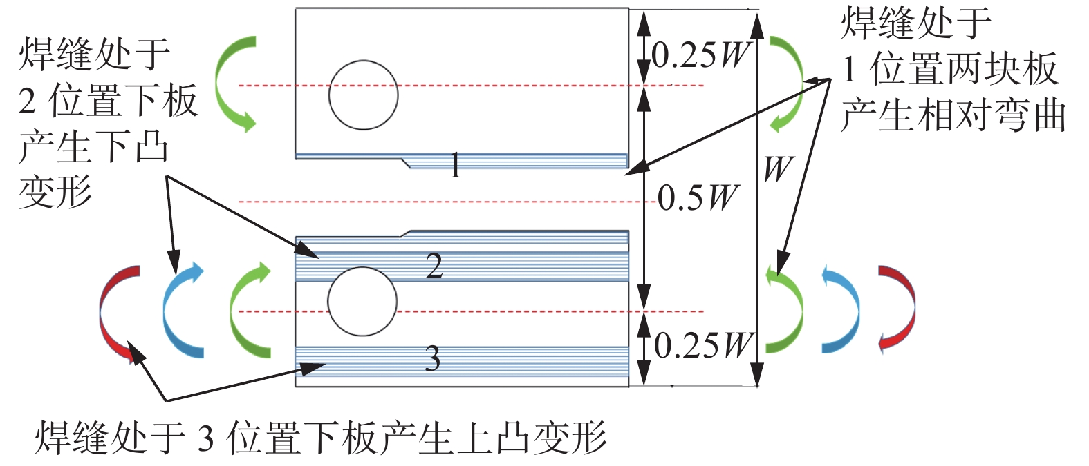
在无横向约束时,横向残余应力的产生原因是焊缝部位的纵向收缩[7],如图10所示,当缺口位于焊缝时,由于焊缝收缩导致上下板产生弯曲变形,这造成CT试样两端为压缩应力,中部为拉伸应力. 当缺口位于焊趾即焊缝位于2位置时,焊缝中心线与板边的距离大于0.25 W,下板产生下凸变形,因此两端为压缩应力,中部为拉伸应力. 当缺口位于母材时即焊缝位于3位置时,焊缝中心线与板边的距离小于0.25 W,下板产生上凸变形,因此两端为拉伸应力,中部为压缩应力.
2.4 纵向残余应力重分布分析
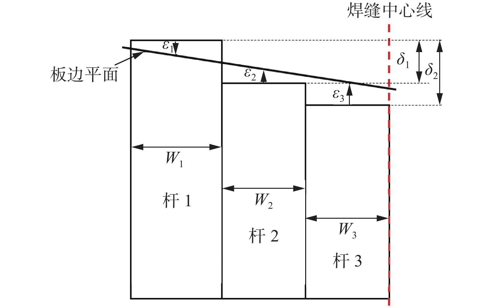
CT试样的纵向残余应力演化规律可以用3-Bar模型解释. 如图11所示,假设三杆的原长为1,
${\delta _{\rm{1}}}$ ,${\delta _{\rm{2}}}$ 分别为杆2和杆3的塑性应变,${\varepsilon _{\rm{1}}}$ ,${\varepsilon _{\rm{2}}}$ ,${\varepsilon _{\rm{3}}}$ 分别为杆1、杆2、杆3在平衡之后的弹性应变,材料的弹性模量为E. 若不考虑焊缝中心线的横向应力,可以仅考虑板材的一半,则有方程组(1)成立.$$\left\{ \begin{array}{l} E({\varepsilon _1}{W_1} + {\varepsilon _2}{W_2} + {\varepsilon _3}{W_3}) = 0\\ {\varepsilon _2}{W_2}({W_1} + {W_2}) + {\varepsilon _3}{W_3}({W_1} + 2{W_2} + {W_3}) = 0\\ ({W_1} + {W_2})({\delta _2} - {\varepsilon _3} + {\varepsilon _1}) - \\ ({W_1} + 2{W_2} + {W_3})({\delta _1} - {\varepsilon _2} + {\varepsilon _1}) = 0 \end{array} \right.$$ (1) 可以求得
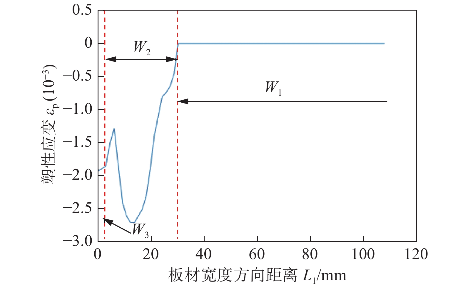
$${\varepsilon _3}{\rm{ = }}\frac{{{\rm{ - [}}{W_1}{W_2}{\rm{(}}{\delta _1}{W_1}{\rm{ + 2}}{\delta _1}{W_2}{\rm{ - }}{\delta _2}{W_1}{\rm{ + }}{\delta _1}{W_3}{\rm{ - }}{\delta _2}{W_2}{\rm{)]}}}}{{({W_1} + 2{W_2} + {W_3})({W_1}{W_2} + {W_1}{W_3} + {W_2}{W_3} + {W_3}^2)}}$$ (2) 设杆1是无塑性应变的母材区域,杆2和杆3的宽度和塑性应变由图12确定. 取
${W_2}$ = 30 mm、${W_3}$ = 3 mm,对${W_2}$ 和${W_3}$ 区间的塑性应变均值化可得${\delta _1}$ = −0.001 4,${\delta _2}$ =−0.001 9.图13显示了在
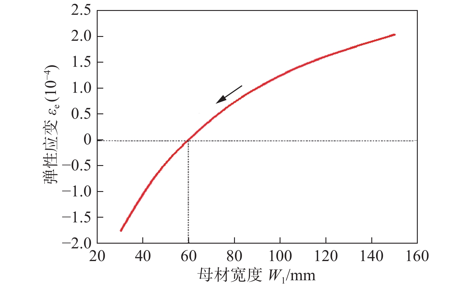
${W_1}$ (即母材宽度)不断变窄的过程中焊缝中心线位置的弹性应变的变化,可以看到,当${W_1}$ 不断减小的过程中,焊缝中心线位置的弹性应变逐渐减小,当${W_1}$ 小于59 mm时,焊缝中心线上的弹性应变由拉伸转变为压缩.3. 结论
(1) 焊接件制成CT紧凑拉伸试样在进行切割前后,残余应力的分布有较大的差异.
(2) 当焊缝中心线距离CT试样板边大于0.25 W时,两端为压缩应力,中部为拉伸应力;小于0.25 W时,两端为拉伸应力,中部为压缩应力.
(3) 在母材逐渐被切除的过程中,焊缝中心线的拉伸残余应力逐渐减小,在母材半宽度小于59 mm时转变为压缩残余应力.
-
表 1 焊接工艺参数
Table 1 Welding parameters
道次 电流
I/A电压
U/V焊接速度
v/(mm·s−1)位置 1(打底) 220 22.5 8.3 正面 2(盖面) 240 24.0 10 正面 3(盖面) 235 24.3 10 背面 -
[1] Hou C Y, Lawrence F V. Crack closure in weldments[J]. Fatigue & Fracture of Engineering Materials & Structures, 2010, 19(6): 683 − 693.
[2] Bussu G, Irving P E. The role of residual stress and heat affected zone properties on fatigue crack propagation in friction stir welded 2024-T351 aluminium joints[J]. International Journal of Fatigue, 2003, 25(1): 77 − 88. doi: 10.1016/S0142-1123(02)00038-5
[3] Fratini L, Pasta S, Reynolds A P. Fatigue crack growth in 2024-T351 friction stir welded joints: Longitudinal residual stress and microstructural effects[J]. International Journal of Fatigue, 2009, 31(3): 495 − 500. doi: 10.1016/j.ijfatigue.2008.05.004
[4] 丁叁叁, 李强, 苟国庆. 残余应力对高速列车A7005铝合金焊接接头疲劳行为的影响[J]. 焊接学报, 2016, 37(9): 23 − 28. Ding Sansan, Li Qiang, Gou Guoqing. Effect of residual stress on fatigue behavior of welded joint of A7005 aluminum alloy for high-speed trcion[J]. Transactions of the China Welding Institution, 2016, 37(9): 23 − 28.
[5] 张正伟, 张昭, 张洪武. 焊接残余应力对2024铝合金薄板疲劳寿命的影响[J]. 焊接学报, 2014, 35(10): 29 − 32. Zhang Zhengwei, Zhangzhao, Zhang Hongwu. Influence of welding residual stresses on fatigue life of Al 2024 plate[J]. Transactions of the China Welding Institution, 2014, 35(10): 29 − 32.
[6] 王强. CRH2型动车车体底架焊接结构可靠性研究[D]. 哈尔滨工业大学, 2012. Wang Qiang. Research on reliability of vehicle chassis welded components of CRH2[D]. Harbin Institute of Technology, 2012.
[7] 方洪渊. 焊接结构学[M]. 北京: 机械工业出版社, 2008. Fang Hongyuan. Mechanics of welding structure[M]. Beijing: Mechanical Industry Press, 2008.
-
期刊类型引用(3)
1. 马亚飞,程尔祥,吴显顺,何羽,王磊. Q550E高强钢及焊接接头的疲劳裂纹扩展研究. 土木与环境工程学报(中英文). 2025(01): 142-151 .  百度学术
百度学术
2. 朱永梅,孙天意,孙志莹,陈建志,张建. 无模胀形蛋形耐压壳的应力重分布分析. 江苏科技大学学报(自然科学版). 2024(06): 1-6 .  百度学术
百度学术
3. 于逸晨,段戈杨,王杰. 铝合金板件残余应力均化与变形控制. 工业技术创新. 2023(03): 41-54 .  百度学术
百度学术
其他类型引用(1)


 下载:
下载:


