
Analysis on TIG welding of TA2 and 0Cr18Ni9 plate based on high entropy of weld
-
摘要: 针对钛/钢焊接难,焊缝易产生金属间化合物导致接头力学性能不良等问题,依据焊缝金属高熵化技术思路,通过基于密度泛函理论的热力学第一性原理设计并制备出塑韧性良好的多主元Ti10Fe29Ni32Cu22V7合金作为焊材,用于TA2/0Cr18Ni9薄板的TIG焊接. 结果表明,使用Ti10Fe29Ni32Cu22V7焊材熔焊钛/钢,所得焊接接头形貌完整,无明显焊接缺陷,焊缝金属与母材结合性良好. 焊缝中心组织则由等轴晶组成,熔合区组织以柱状晶为特征,这些晶体均具有简单立方固溶体结构,有效避免了TiFe2,TiFe金属间化合物的形成,接头抗拉强度达到205 MPa.Abstract: In order to solve the problem of poor mechanical properties of joint caused by intermetallic compounds in the welding seam of titanium/steel, according to the high entropy technology of weld metal, the multi-component Ti10Fe29Ni32Cu22V7 alloy with good plasticity and toughness was designed and prepared according to the first principles of thermodynamics based on density functional theory, which was used for TIG welding of TA2/0Cr18Ni9 sheet. The results show that: using Ti10Fe29Ni32Cu22V7 welding material for fusion welding titanium/steel, the welding joint morphology is complete, no obvious welding defects, and the bonding between weld metal and base metal is good. The microstructure of the weld center is composed of equiaxed grains, and the microstructure of the fusion zone is characterized by columnar crystals. These crystals have a simple cubic solid solution structure, which effectively avoids the formation of intermetallic compounds. The tensile strength of the joint is high, up to 205 MPa.
-
0. 序言
搅拌摩擦焊(friction stir welding, FSW)作为一种固相焊接技术,具有焊缝质量高、变形小等优点[1-2]. 目前加工制造业对焊接智能化、高效化的要求日益上升,机器人搅拌摩擦焊得以更普遍的应用.在实际大型结构的FSW生产中,由于接头形式、板材加工精度以及工装夹具装配质量问题,焊接过程容易产生较大的间隙,对接头的成形和性能极为不利[3-4],当工件之间的间隙超过工件厚度的10%时,很难获得无缺陷质量良好的接头[5]. 间隙的存在导致焊核区(weld nugget zone,WNZ)材料流动不充分,焊缝出现孔洞和隧道等缺陷[6]. 同时,工件被塑化的材料流入间隙,弥补材料缺失使得焊缝位置减薄严重,降低接头承载能力[7].
研究人员[8-9]采用粉末、焊丝或者补偿条作为填充材料对大间隙下的工件进行FSW,得到成形良好无缺陷的接头,接头与常规FSW接头力学性能吻合,然而,当焊接速度过快时,这些填充材料很容易飞出间隙,从而形成缺陷. 同时填充材料需要在焊前放置在间隙内,针对复杂结构间隙及焊接过程中产生的间隙,填充材料的尺寸以及填料的连续性受到限制.
基于传统搅拌摩擦焊方法,填充材料旁轴送料,将FSW与填料过程同时进行,实现大间隙机器人搅拌摩擦填丝焊,并对其接头进行盐雾腐蚀试验,分析搅拌摩擦填丝焊接头不同区域的腐蚀行为差异.搅拌摩擦填丝焊提高了FSW对工况条件的适应性,适用于高铁、船舶和飞机上大型及复杂结构焊缝,有望为工程实际应用提供理论依据和技术支撑.
1. 试验方法
试验材料为5A06铝合金轧制板材,尺寸为300 mm × 70 mm × 3 mm,填充材料为直径1.6 mm的5B06丝材. 机器人搅拌摩擦填丝焊焊接过程示意图及焊具尺寸如图1所示,对接板材焊接间隙为2 mm. 填充丝材经过高推力送丝系统从送丝孔连续输送到储料腔内部,高速旋转的螺杆将金属丝材剪切成粒状材料,粒状材料在自身重力及与螺杆侧壁的摩擦力的影响下,在储料腔内塑化从底部的缝隙流出. 轴向压力使储料腔与板材之间产生挤压效果,粒状材料发生变形堆积并被塑化. 在旋转的搅拌针的驱动作用下,塑化的填充材料发生流动并实现与基材的连接. 试验所采用的焊接工艺参数为转速3 000 r/min,焊接速度200 mm/min,送丝速度1.8 m/min,轴向压力5 000 N,倾角1.5°.
![]() 图 1 焊接过程示意图及焊具结构Figure 1. Welding process and the welding tool structure. (a) schematic illustration of wire-feeding friction stir welding; (b) dimensions of the welding tool
图 1 焊接过程示意图及焊具结构Figure 1. Welding process and the welding tool structure. (a) schematic illustration of wire-feeding friction stir welding; (b) dimensions of the welding tool2. 试验结果与分析
2.1 焊缝成形
图2为机器人搅拌摩擦填丝焊接头焊缝表面形貌. 焊缝表面光滑成形良好,无沟槽缺陷,在搅拌针的驱动作用下,塑化的填充材料发生流动后沉积弥补了间隙位置材料缺失,同时焊缝有一定程度的增厚,提高了接头的承载能力.
2.2 焊缝微观组织
图3为焊缝整体微观形貌及不同区域的微观组织. 焊接接头填充材料与基体母材结合良好,焊缝无孔洞及隧道缺陷,由于搅拌针的存在,搅拌针促进塑化的丝材和基材发生流动,提高了填充材料与基材的结合效果. 丝材经过螺杆的剪切及静轴肩的挤压作用,与焊核区受到搅拌针的搅拌作用一样,填充材料也经历了大塑性变形,发生动态再结晶,形成细小的等轴晶.
![]() 图 3 搅拌摩擦填丝焊接头微观组织Figure 3. Microstructures of wire-feeding friction stir welding. (a) microstructures of the cross-section; (b) top interface; (c) thermo-mechanically affected zone interface; (d) filler materials zone
图 3 搅拌摩擦填丝焊接头微观组织Figure 3. Microstructures of wire-feeding friction stir welding. (a) microstructures of the cross-section; (b) top interface; (c) thermo-mechanically affected zone interface; (d) filler materials zone2.3 焊缝腐蚀性能
搅拌摩擦填丝焊接头经过7天盐雾腐蚀试验后接头各区域腐蚀形貌如图4所示. 接头表面均发生了点蚀坑的萌生, 表面出现腐蚀产物;焊核区及填充材料区域的点蚀坑尺寸较小,且分布较为均匀;母材点蚀坑分布不均匀,尺寸较大.热力影响区(thermo- mechanically affected zone,TMAZ)的点蚀坑随晶粒分布特征呈流线分布,热影响区(heat-affected zone,HAZ)的点蚀坑尺寸较大,且出现一定的聚集现象,点蚀坑发生扩展.焊核区和填充材料区表现出更好的耐腐蚀性能.
![]() 图 4 不同区域盐雾腐蚀形貌Figure 4. Salt spray corrosion morphologies in different zones. (a) WNZ; (b) filler materials zone; (c)TMAZ; (d) HAZ; (e)BM
图 4 不同区域盐雾腐蚀形貌Figure 4. Salt spray corrosion morphologies in different zones. (a) WNZ; (b) filler materials zone; (c)TMAZ; (d) HAZ; (e)BM第二相分布及尺寸对点蚀坑的形成有巨大影响,第二相和基体之间形成微电偶会导致腐蚀现象发生.焊核区经过塑性变形后第二相颗粒被打碎,尺寸较小分布也更均匀,进而发生腐蚀现象后点蚀坑分布均匀细小;填充材料区域拥有更小且弥散分布的第二相颗粒,填充材料的加入增强了焊核区的耐蚀性.经过轧制后的母材中第二相颗粒尺寸较大且分布不均匀,耐蚀性较差易形成较大的点蚀坑;热力影响区点蚀坑呈流线分布,而热影响区第二相颗粒发生聚集长大,发生点蚀后有利于点蚀坑的扩展,导致热影响区的耐蚀性较差.
图5为热影响区点蚀坑SEM图及附近元素分布.发现在第二相Al6(FeMn)附近产生了明显的腐蚀现象, 点蚀坑发生扩展. 在盐雾环境中,铝合金表面虽然存在一层氧化膜,但是随着溶液中Cl−的侵入,Cl−破坏了表面氧化膜,促进点蚀现象发生. 同时热影响区第二相颗粒Al6(FeMn)与铝基体之间存在腐蚀电位差形成原电池,由于Al6(FeMn)电位高于铝基体[10],第二相颗粒在腐蚀过程中充当阴极,促使周围基体发生腐蚀,因此在第二相附近形成环形腐蚀区域产生腐蚀坑并向四周扩展. 当第二相尺寸较大时,周围基体溶解的范围增大,点蚀坑的尺寸也会更大. 基于元素分布图可以看出,在腐蚀坑附近Al元素含量减少,点蚀坑内金属发生溶解,点蚀孔内阳离子浓度升高,Cl−就会不断侵入以维持平衡.随着Cl−浓度的升高发生水解,导致点蚀坑内部氢离子浓度升高,溶液酸化,促使基体进一步溶解,点蚀坑发生扩展.
2.4 接头力学性能
图6为经过7天盐雾腐蚀接头、未腐蚀接头及母材的拉伸测试结果.未腐蚀接头抗拉强度为388.9 MPa ± 1.4 MPa,断后伸长率为20.5% ± 0.4%,分别达到母材的99%及94%. 经过7天盐雾腐蚀后接头抗拉强度降低到356.6 MPa ± 1.2 MPa,断后伸长率为18.1% ± 0.9%,盐雾腐蚀后接头强度降低了8.3%,断后伸长率下降了11.7%,盐雾腐蚀试验后接头仍保持较优的力学性能. 盐雾腐蚀环境造成焊缝表面出现点蚀坑,而富Cl−环境使基体金属进一步溶解,点蚀坑发生扩展,减少了接头有效承载面积,在承受载荷时其易成为薄弱位置,裂纹在点蚀坑位置产生,降低了接头承载能力.
3. 结论
(1) 实现了大尺寸间隙下机器人搅拌摩擦填丝焊,焊接过程与填料过程同时进行,提高了搅拌摩擦焊对接头间隙的容忍性,消除了焊缝减薄问题.
(2) 填充材料与基材实现了良好的冶金连接,经过剧烈塑性变形后,焊核区和填充材料发生动态再结晶,表现为细小的等轴晶粒.
(3) 未腐蚀接头抗拉强度达到388.9 MPa ± 1.4 MPa,断后伸长率为20.5% ± 0.4%,分别达到母材的99%及94%. 在腐蚀过程中焊核区和填充材料区耐腐蚀性能优于热影响区与母材,点蚀坑细小且均匀分布,7天盐雾腐蚀后接头保持优异的耐蚀性能.
-
![]()
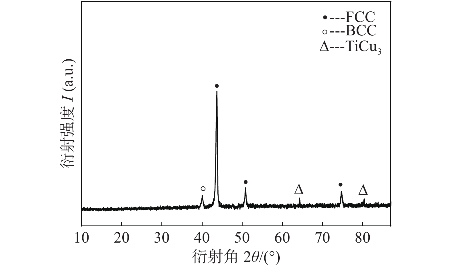
图 1 TA2/0Cr18Ni9焊缝的XRD图谱
Figure 1. X-ray pattern of weld in the the joint of TA2/0Cr18Ni9
![]()
图 2 用Ti10Fe29Ni32Cu22V7 TIG焊TA2/0Cr18Ni9获得的接头组织
Figure 2. Microstructure of the TA2/0Cr18Ni9 TIG welding joint by using Ti10Fe29Ni32Cu22V7 alloy. (a) morphology of TA2/0Cr18Ni9 joint; (b) weld near 0Cr18Ni9; (c) center of the weld; (d) weld near TA2
![]()
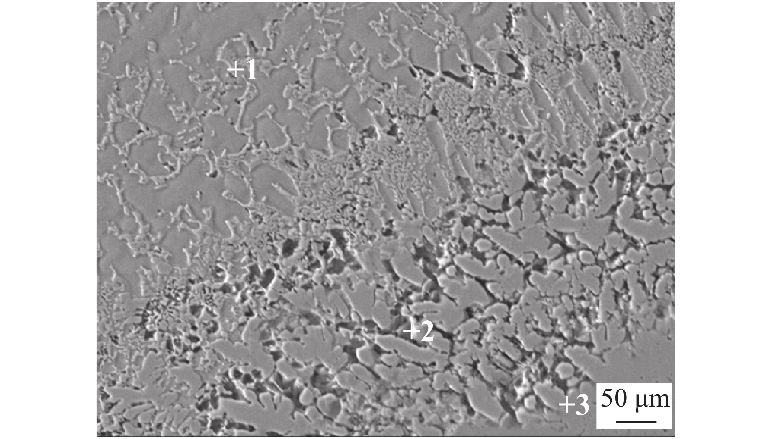
图 3 TIG焊TA2/0Cr18Ni9焊缝中心组织及EDS测点位置
Figure 3. Microstructure and measuring points of weld center of TA2/0Cr18Ni9 GTAW
![]()
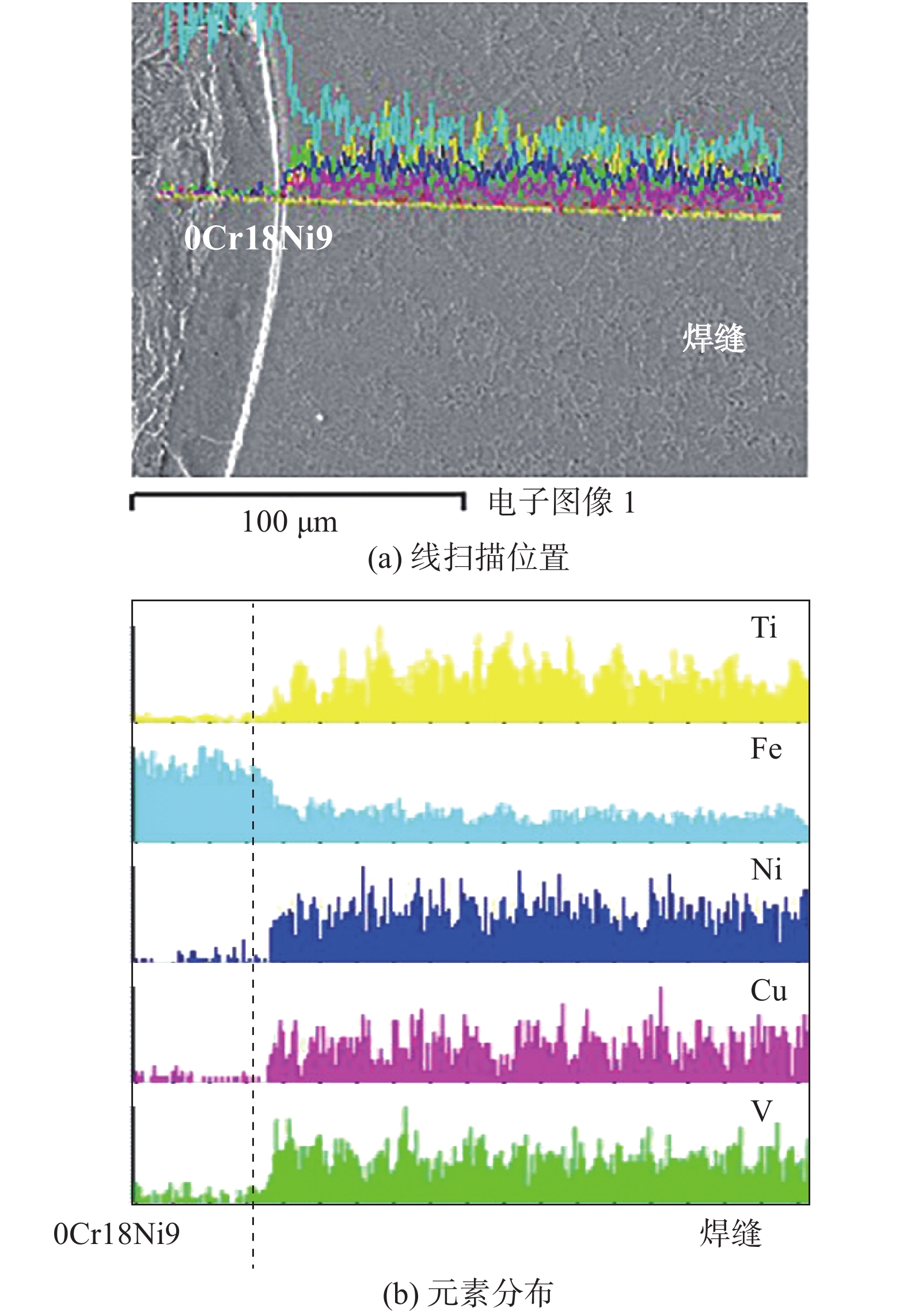
图 4 TA2/0Cr18Ni9 TIG焊焊缝线扫描图
Figure 4. Line scanning position spectrums of weld metal of TA2/0Cr18Ni9 GTAW. (a) line scanning position; (b) distribution of elements
![]()
图 6 TA2/0Cr18Ni9 TIG焊接接头拉伸断口形貌(TA2侧)
Figure 6. The tensile fracture morphology of the joint near TA2 of TA2/0Cr18Ni9 GTAW
表 1 钛/钢TIG焊工艺参数
Table 1 The parameters of GTAW titanium and steel
焊接电流I/A 焊接速度v/(mm·min−1) 氩气流量Q/(L·min−1) 喷嘴直径D1/mm 钨极直径D2/mm 焊丝伸出长度L/mm 滞后断气时间t/s 60~80 60~100 12~15 10 3 4~6 3~5  下载: 导出CSV
表 2 主元原子半径差、混合焓、混合熵及Ω值
Table 2 The atomic radius difference, enthalpy of mixing, entropy of mixing and Ω value of main elements
Ti含量
(原子分数, %)原子半径差
δ(%)混合焓
ΔHmix/
(kJ·mol−1)混合熵
ΔSmix/
(J·K−1·mol−1)Ω值[13] x =5 3.44 −2.02 11.74 9.94 x = 8 4.04 −4.26 12.09 4.87 x = 10 4.37 −5.67 12.26 3.73 x = 12 4.65 −7.01 12.39 3.05 x = 14 4.91 −8.29 12.50 2.61
下载: 导出CSV
表 3 高熵合金Tix[Fe32Ni36Cu24V8]100−x的弹性系数
Table 3 Elastic constants of high entropy alloys Tix[Fe32Ni36Cu24V8]100−x
Ti含量(原子分数, %) C11/GPa C12/GPa C44/GPa 体模量B/GPa 剪切模量G/GPa 弹性模量E/GPa G/B 泊松比v x = 5 341.063 245.170 8 133.511 2 277.134 8 88.593 4 240.186 2 0.319 7 0.355 6 x = 8 321.095 2 236.841 4 127.855 6 264.926 0 82.023 3 223.050 5 0.309 6 0.359 7 x = 10 309.095 5 240.039 4 127.524 2 263.058 1 75.856 9 207.614 5 0.288 36 0.368 5 x = 12 313.276 3 238.929 3 130.254 7 263.711 6 79.049 0 215.604 2 0.299 8 0.363 7 x = 14 303.651 4 227.615 124.976 2 252.960 5 77.728 9 211.521 5 0.307 3 0.360 6 注:C11, C12, C44为理论计算出的弹性系数
下载: 导出CSV
表 4 TIG焊TA2/0Cr8Ni9焊缝中心EDS测试结果(原子分数,%)
Table 4 EDS results of weld center of TA2/0Cr18Ni9 GTAW
位置 Ti Fe Ni Cu V 1 30.57 36.07 21.45 5.44 6.47 2 27.36 39.69 18.92 6.31 7.72 3 43.04 21.92 20.58 9.21 5.26
下载: 导出CSV
-
[1] 刘世锋, 宋玺, 薛彤, 等. 钛合金及钛基复合材料在航空航天的应用和发展[J]. 航空材料学报, 2020, 40(3): 77 − 94. Liu Shifeng, Song Xi, Xue Tong, et al. Application and development of titanium alloy and titanium matrix composites in aerospace field[J]. Journal of Aeronautical Materials, 2020, 40(3): 77 − 94.
[2] Chu Q L, Zhang M, Li J H, et al. Experimental investigation of explosion-welded CP-Ti/Q345 bimetallic sheet filled with Cu/V based flux-cored wire[J]. Materials & Design, 2015, 67: 606 − 614.
[3] Chu Qiaoling, Zhang Min, Li Jihong, et al. Influence of vanadium filler on the properties of titanium and steel TIG welded joints[J]. Journal of Materials Processing Technology, 2017(240): 293 − 304.
[4] 张鹏贤, 李世龙. 铬、铌、钒金属粉末为过渡层的钛/钢电阻钎焊研究[J]. 热加工工艺, 2018, 47(21): 53 − 56. Zhang Pengxian, Li Shilong. Resistance brazing of titanium/steel using Cr, Nb, V metal powder as transition layer[J]. Hot Working Technology, 2018, 47(21): 53 − 56.
[5] 邓云华, 岳喜山, 李晓辉, 等. TC4钛合金/304不锈钢异种材料蜂窝结构钎焊工艺[J]. 焊接学报, 2019, 40(10): 148 − 155. Deng Yunhua, Yue Xishan, Li Xiaohui, et al. Brazing process of TC4 titanium/304 stainless steel dissimilar materials honeycomb sandwich structure[J]. Transactions of the China Welding Institution, 2019, 40(10): 148 − 155.
[6] 刘夫, 李士凯, 蒋鹏, 等. 钛/钢异种金属焊接技术的研究进展[J]. 材料开发与应用, 2020, 35(2): 67 − 74. Liu Fu, Li Shikai, Jiang Peng, et al. Development progress of welding technologies of titanium/steel dissimilar metal[J]. Development and Application of Materials, 2020, 35(2): 67 − 74.
[7] Zhao B, Jian D, Ma L, et al. Precipitation of intermetallic compounds in brazing of titanium and steel using brass filler[J]. Journal of Materials Processing Technology, 2020, 285: 116730. doi: 10.1016/j.jmatprotec.2020.116730
[8] Y Yeh J W, Chen S K, Lin S J, et al. Nanostructured high-entropy alloys with multiple principal elements: novel alloy design concepts and outcomes[J]. Advanced Engineering Materials, 2004, 6(5): 299 − 303. doi: 10.1002/adem.200300567
[9] 王兰馨, 姚山, 温斌. 第一性原理计算Fe含量对高熵合金AlFexTiCrZnCu力学性能的影响[J]. 材料导报, 2019, 33(S2): 356 − 359. Wang Lanxin, Yao Shan, Wen Bin. First-principle studies of AlFexTiCrZnCu high entropy alloys with the different mole fractions of Fe[J]. Materials Reports, 2019, 33(S2): 356 − 359.
[10] Yong Z, Yun J Z, Jun P L, et al. Solid-solution phase formation rules for multi-component alloys[J]. Advanced Engineering Materials, 2010, 10(6): 534 − 538.
[11] Yang X, Zhang Y. Prediction of high-entropy stabilized solid-solution in multi-component alloys[J]. Materials Chemistry & Physics, 2012, 132(2-3): 233 − 238.
[12] Guo S, Ng C, Lu J, et al. Effect of valence electron concentration on stability of fcc or bcc phase in high entropy alloys[J]. Journal of Applied Physics, 2011, 109(10): 645 − 647.
[13] 翟秋亚, 刘帅宾, 杨全虎, 等. Ta1/0Cr18Ni9薄板储能焊熔核高熵化机理[J]. 焊接学报, 2020, 41(8): 79 − 84. Zhai Qiuya, Liu Shuaibin, Yang Quanhu, et al. High entropy mechanism of nugget in Ta1/0Cr18Ni9 sheet energy storage welding[J]. Thansactions of the China Welding Institution, 2020, 41(8): 79 − 84.
[14] Takeuchi A, Inoue A. Classification of bulk metallic glasses by atomic size difference, heat of mixing and period of constituent elements and its application to characterization of the main alloying element[J]. Materials Transactions, 2005, 46(12): 2817 − 2829. doi: 10.2320/matertrans.46.2817


计量
- 文章访问数: 420
- HTML全文浏览量: 21
- PDF下载量: 26
