
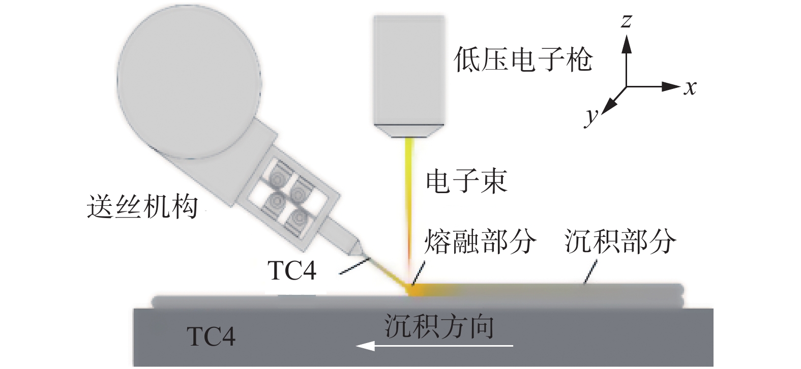
Microstructure and properties of low voltage electron beam wire deposition layer of TC4 titanium alloy
-
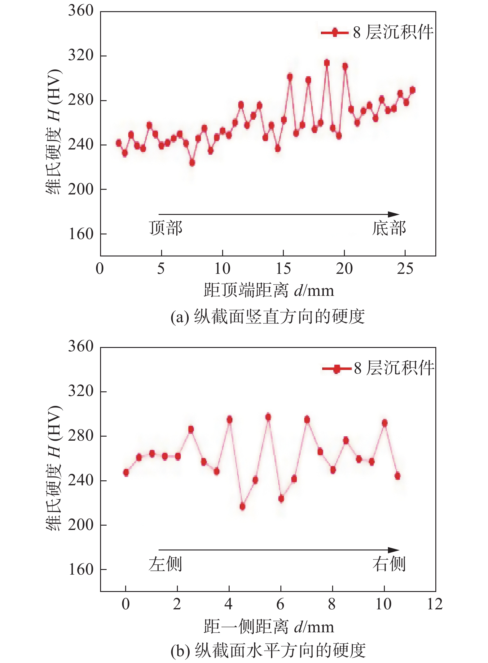
摘要: 对TC4钛合金进行了低压电子束熔丝沉积试验,探究了该方法的可行性,并分析了沉积层数对微观组织和性能的影响. 结果表明,在加速电压为10 kV的低压时也可完成TC4钛合金的多层熔丝沉积. 多层沉积之后得到的沉积件的平均显微硬度在260 HV左右,只有沉积件底部条带状纹理聚集处的显微硬度接近退火态TC4基材的288 HV. 条带状纹理产生于多层沉积的过程之中,β相晶粒受热循环影响而发生了β → α + α′ + β的转变,其中硬度较高的网篮状α′相与片状的α相组成了条带状纹理,该显微组织的特点是随着与基板距离的增加,网篮状组织逐渐融入片状组织. 沉积件的拉伸断裂形式为韧性断裂,最高抗拉强度为862 MPa,略低于国家标准,这是因为在多层沉积的沉积件中β柱状晶会变得巨大,同时还会出现等轴晶,晶粒的巨大化使得沉积件的抗拉性能出现了下降.Abstract: The low voltage electron beam wire deposition tests on TC4 titanium alloy were carried out to explore the feasibility of the method, and the influence of the number of deposited layers on the microstructure and properties was analyzed. The results show that the multi-layer wire deposition of TC4 titanium alloy can also be completed on the accelerated voltage of 10 kV. The average microhardness of the deposited parts after multi-layer deposition is about 260 HV, and only the microhardness of the banded texture at the bottom of the deposited parts is close to 288 HV of the annealed TC4 substrate. Banded texture produced in multi-layer deposition process, β phase grain transformed to α + α′ + β by the influence of thermal cycle, the banded texture which composited with basket-like α′ phase and lamellar α phase have high microhardness, the other feature of banded texture is that more basket-like phase gradually integrated into the lamellar structure as the increase of the distance with substrate. The tensile fracture of the deposited part is also ductile fracture with the maximum tensile strength of 862 MPa, which is slightly lower than the national standard. It because the columnar crystals will become huge in the deposited parts with multiple layers, and equiaxed crystals will also appear. The huge size of the grains will decrease the tensile properties of the deposited parts.
-
0. 序言
在桥梁、舰艇、海工、水电和压力容器等国民经济支柱行业,为满足装备轻量化的要求,屈服强度为690 MPa级高强钢具有广泛的应用前景[1-3]. 由于焊缝金属为典型的铸态组织,并且不能像板材一样进行热变形处理,690 MPa级及以上强度焊缝金属强韧性匹配困难,工程上常以牺牲焊接接头的韧性为代价来满足接头的强度匹配,这给焊接结构的安全服役带来了一定隐患. 研究690 MPa级高强钢焊缝金属的强韧化机理,实现焊接结构良好的强韧性匹配,具有重要的意义. 现有的690 MPa级焊缝金属一般采用C,Mn,Ni,Cr和Mo等元素进行固溶强化或相变强化,焊缝金属微观组织主要为贝氏体、马氏体或二者的混合组织,由于这类组织特殊的切变机制,位错密度相对较高,焊缝金属具有较高的强度而低温韧性较差[4-6].
关于690 MPa级焊缝金属强韧性的研究,目前公开较少,且焊缝金属成分主要集中在传统成分范围内,焊缝金属强韧性匹配困难,因此应探索实现更好强韧性匹配的新途径. 文中以具有较低镍当量(Nieq = 30C% + Ni% + 0.5Mn%)的传统690 MPa级焊缝金属和自研的具有较高Mneq的新型690 MPa级焊缝金属为对象,系统研究了合金成分对焊缝金属微观组织以及力学性能的影响规律,在此基础上阐明了690 MPa级焊缝金属的强韧化机理,为高强韧性焊接材料的开发以及焊接接头性能调控提供了一定的依据和参考.
1. 试验方法
采用两种典型成分690 MPa级低氢碱性焊条制备焊缝金属,焊条直径为4.0 mm,焊缝金属的化学成分,如表1所示. HT-01焊条为传统成分系焊条,焊缝金属Nieq为4.51%;HT-02焊条为自研的新型成分系焊条,焊缝金属Nieq为6.43%. 针对两种典型成分系焊条,按照美国焊接协会标准AWS A5.5《Specification for Low-Alloy Steel Electrodes for Shielded Metal Arc Welding》进行熔敷试板焊接,焊接电流为160 ~ 180A,道间温度为80 ~ 120 ℃,焊接热输入约为20 kJ/cm. 焊缝金属制备完成后,按照国家标准GB/T 2652-2008《焊缝及熔敷金属拉伸试验方法》进行拉伸试验,按照国家标准GB/T 2650-2008《焊接接头冲击试验方法》进行焊缝金属−50 ℃夏比冲击试验,缺口位置位于焊缝中心. 沿垂直于焊缝的横截面方向取样,进行金相组织表征,常规金相采用3%的硝酸酒精进行腐蚀,彩色金相采用1% Na2S2O5水溶液和3%体积分数的苦味酸酒精按体积比1∶1混合的Lepera试剂进行腐蚀. 金相组织观察采用ZEISS AXIO Observer 7 materials金相显微镜. 微区硬度测试采用Wilson VH3300型维氏硬度仪,试验力为0.49 N. 透射电子显微镜(transmission electron microscopy, TEM)样品薄区制备采用电解双喷仪,电解液为10%的高氯酸酒精,电压控制在24 ~ 26 V,温度控制在−25 ~ −20 ℃,采用JEM2100型TEM对薄区进行微观组织表征. 焊缝金属微区成分分析采用EPMA-1610电子探针进行电子探针显微分析(electro-probe microanalysis, EPMA). 采用Quanta650扫描电子显微镜进行冲击断口形貌以及一次裂纹扩展观察.
表 1 焊缝金属化学成分(质量分数,%)Table 1. Chemical compositions of weld metals焊条编号 C Si Cr + Mo Mn Ni Nieq HT-01 0.043 0.327 0.885 1.60 2.42 4.51 HT-02 0.037 0.302 0.312 0.88 4.88 6.43 2. 试验结果与分析
2.1 焊缝金属力学性能与微观组织
焊缝金属的力学性能,如表2所示. HT-01焊缝金属和HT-02焊缝金属的屈服强度分别为736 MPa和738 MPa,抗拉强度分别为797 MPa和805 MPa,−50 ℃冲击吸收能量均值分别为59 J和122 J. 两个成分焊缝金属强度相差不大,但HT-02焊缝金属的−50 ℃冲击吸收能量显著高于HT-01.
表 2 焊缝金属力学性能Table 2. Mechanical properties of weld metals焊条编号 屈服强度ReL/MPa 抗拉强度Rm/MPa 断后伸长率A(%) 断面收缩率Z(%) −50 ℃冲击吸收能量AkV/J HT-01 736 797 20.0 66 59 HT-02 738 805 20.5 68 122 焊缝金属的金相组织,如图1所示. HT-01焊缝金属组织相对均一,主要为粗大的GB,在GB基体上存在大量的马氏体—奥氏体(martensite-austenite M-A)岛,在枝晶间区域有一定LM. HT-02焊缝金属微观组织与HT-01差异较大,具有显著的不均一性,呈明显的“条带状”特征. 焊缝金属凝固过程中合金元素易向枝晶间区域偏析,枝晶间区域耐腐蚀性能大于枝晶干区域,故在光学显微镜下呈现白色“条带状”. 枝晶干区域主要为AF,而枝晶间组织较细,光学显微镜无法确定其组织类型.
TEM下焊缝金属的微观组织,如图2所示. 在HT-01焊缝金属M-A中存在孪晶马氏体(twin martensite,TM). TM是一种高硬度组织,容易造成组织不协调变形,恶化焊缝金属的低温韧性[7-8]. HT-02焊缝金属枝晶间为呈交织状分布的LM,在LM板条间有薄膜状残余奥氏体. 焊缝金属−50 ℃冲击断口形貌,如图3所示. HT-01焊缝金属纤维区宽度约为800 μm,其余为放射区和剪切唇区,而HT-02焊缝金属主要为纤维区和剪切唇区,反映出HT-02焊缝金属的低温韧性高于HT-01. HT-01焊缝金属纤维区有大量扁平状韧窝,放射区为典型的准解理形貌. HT-02焊缝金属纤维区主要为细小的韧窝,仅在断口中心附近的纤维区有少量的解理断裂.
![]() 图 2 TEM下焊缝金属的微观组织Figure 2. Microstructure of weld metals under TEM. (a) TM of HT-01; (b) bright field phase of interdendritic retained austenite of HT-02; (c) dark field phase of interdendritic retained austenite of HT-02
图 2 TEM下焊缝金属的微观组织Figure 2. Microstructure of weld metals under TEM. (a) TM of HT-01; (b) bright field phase of interdendritic retained austenite of HT-02; (c) dark field phase of interdendritic retained austenite of HT-02![]() 图 3 焊缝金属−50 ℃夏比冲击断口形貌Figure 3. Charpy impact fracture morphology of weld metals at −50 ℃. (a) HT-01; (b) fiber zone of HT-01; (c) radiation zone of HT-01; (d) HT-02; (e) fiber zone of HT-02; (f) cleavage fracture plane of HT-02
图 3 焊缝金属−50 ℃夏比冲击断口形貌Figure 3. Charpy impact fracture morphology of weld metals at −50 ℃. (a) HT-01; (b) fiber zone of HT-01; (c) radiation zone of HT-01; (d) HT-02; (e) fiber zone of HT-02; (f) cleavage fracture plane of HT-02焊缝金属−50 ℃冲击断口一次裂纹形貌,如图4所示. 结果显示HT-01焊缝金属断口比较平直,而HT-02断口比较曲折,在视野范围内发生多次偏转.从一次裂纹局部放大来看,HT-01焊缝具有较粗大的贝氏体,一次裂纹在贝氏体边界无明显偏转,说明其对裂纹扩展的阻碍作用较小;HT-02焊缝金属具有细小的AF,在大部分AF部位裂纹扩展方向发生明显偏转,说明AF对裂纹扩展具有显著的阻碍作用.
![]() 图 4 焊缝金属−50 ℃夏比冲击断口一次裂纹Figure 4. Charpy impact main crack of weld metals at −50 ℃. (a) HT-01; (b) local amplification of Fig. 4(a); (c) HT-02; (d) local amplification of Fig. 4(c)
图 4 焊缝金属−50 ℃夏比冲击断口一次裂纹Figure 4. Charpy impact main crack of weld metals at −50 ℃. (a) HT-01; (b) local amplification of Fig. 4(a); (c) HT-02; (d) local amplification of Fig. 4(c)2.2 分析与讨论
由于高强钢焊缝金属的组织细小,采用传统的硝酸酒精腐蚀的金相很难进行精准的组织鉴定. 彩色金相通过在金属表面形成一层极薄的干涉膜,利用薄膜的干涉效应使金属微观组织产生不同的干涉色,可以显著提高对金属组织的鉴别能力[9-11]. 在Lepera试剂腐蚀的彩色金相下奥氏体和马氏体一般被染为黄/白色,贝氏体和铁素体被染为蓝色[9-11]. 两种典型成分焊缝金属的彩色金相,如图5所示. HT-02呈典型的“条带”状特征,这些“条带状”组织位于枝晶间区域,结合TEM结果可知为LM和残余奥氏体;这些“条带”间的蓝色区域为枝晶干区域为AF.
![]() 图 5 焊缝金属彩色金相组织Figure 5. Color Metallographic structure of weld metals. (a) HT-01; (b) HT-02
图 5 焊缝金属彩色金相组织Figure 5. Color Metallographic structure of weld metals. (a) HT-01; (b) HT-02枝晶干区域的宽度约为20μm,枝晶间区域宽度约为3μm. 采用EPMA对枝晶干区域和枝晶间区域元素含量进行了打点检测,HT-01焊缝金属枝晶间区域和枝晶干区域的Mn含量分别为1.29%和1.20%,差值为0.09%;枝晶间区域和枝晶干区域的Ni含量分别为3.91%和3.52%,差值为0.39%. HT-02焊缝金属枝晶间区域和枝晶干区域Mn含量分别为1.39%和1.03%,差值为0.36%;枝晶间区域和枝晶干区域Ni含量分别为5.68%和4.57%,差值为1.11%. 可知HT-02 焊缝金属相对HT-01焊缝金属Mn,Ni在枝晶间发生了显著偏析. 合金偏析程度可以采用Scheil方程[12]来估算,即
$$ C_{\mathrm{S}} = k_0 C_0\left[1-f_{\mathrm{S}}\right]^{k-1} $$ (1) 式中:CS为固相成分;C0为溶质的浓度;k为溶质平衡分配系数;fS为液相体积分数.
当k<1时,合金元素向枝晶间偏析,且k值越小,偏析的倾向越大.
在合金钢中Mn,Ni的k值均小于1,故两种元素均易在枝晶间偏析,文献[13-14]的研究结果表明,Mn,Ni在低合金高强钢焊缝金属枝晶间存在偏析现象. 孙健[15]采用经典的扩散方程计算了焊缝金属中C,Mn和Ni在
1400 K实现均匀化所需要的时间,分别为0.26 s,9107 s和32524 s. 在实际焊接过程中焊缝金属冷却速度极大,焊条电弧焊从凝固结束冷却至500 ℃经历约20 s. 因此,在高强钢焊接过程中C可能通过扩散实现一定程度的均匀化,而Mn、Ni等元素的扩散可以忽略不计,仍然会在枝晶间富集,将对焊缝金属的组织产生重要的影响.测试HT-02焊缝金属的硬度,枝晶间区域和枝晶干区域的显微硬度分别为358 HV0.05和294 HV0.05. 枝晶间区域组织主要为LM,而枝晶干区域主要为组织AF,故枝晶间区域的硬度要大于枝晶干区域.基于典型成分焊缝金属微观组织分析和力学性能测试结果,690 MPa级焊缝金属的强韧化机制,如图6所示. 传统的焊缝金属(HT-01)的Nieq较小,凝固时偏析相对较小,枝晶间区域和枝晶干区域过冷奥氏体的稳定性差别不大,故形成了以粗大GB为主的相对均一组织. M-A岛中有TM生成,由于TM硬而脆,容易诱导微裂纹的萌生,同时粗大的贝氏体铁素体对裂纹扩展的阻力较小,故焊缝金属低温韧性较差. 新型焊缝金属Nieq较大,凝固时奥氏体稳定化元素Mn,Ni易在枝晶间显著偏析,导致枝晶间区域过冷奥氏体的稳定性大于枝晶干区域.在焊缝金属冷却过程中,过冷奥氏体稳定性较小的枝晶干区域首先转变为AF,随后过冷奥氏体稳定性较大的枝晶间区域转变为LM,形成软硬相结合的复相组织. 并且先形成的AF对原奥氏体晶粒具有一定的分割作用,阻碍了后续粗大M的形成. 最终焊缝金属形成AF(枝晶干) + LM(枝晶间)的细小复相组织. 枝晶干区域形成的AF取向差比较大,对裂纹扩展具有较大的阻碍作用,可显著提高低温韧性,同时在枝晶间形成的LM板条间有一定量薄膜状残余奥氏体,这些残余奥氏体薄膜对提高焊缝金属的低温韧性也具有一定的作用[14-15]. 枝晶干区域先形成的AF为主要的韧化相,枝晶间区域后形成的LM为主要的强化相,这种具有韧性相 + 强化相的细小复合组织具有优异的强韧性匹配.
![]() 图 6 焊缝金属的强韧化机制Figure 6. Strengthening and toughening mechanism of weld metals. (a) traditional weld metal; (b) new weld metal
图 6 焊缝金属的强韧化机制Figure 6. Strengthening and toughening mechanism of weld metals. (a) traditional weld metal; (b) new weld metal3. 结论
(1)传统690 MPa级高强钢焊缝金属由于Nieq较小,无明显的成分偏析,枝晶干区域和枝晶间区域过冷奥氏体的稳定性差别不大,形成了粗大的GB为主的组织. 粗大的GB易萌生裂纹且对裂纹扩展阻力较小,故焊缝金属低温韧性较差.
(2)新型690 MPa级焊缝金属Nieq较大,由于Mn,Ni在枝晶间区域偏析,枝晶间区域过冷奥氏的稳定性大于枝晶干区域.焊缝金属冷却过程中,在过冷奥氏体稳定性较小的枝晶干区域先形成AF,随着进一步冷却,在过冷奥氏体稳定性较大的枝晶间区域形成LM. AF取向差比较大,裂纹在其中扩展时易发生偏转,可提高焊缝金属的韧性,而LM具有较高的强度,两者形成的复相组织具有良好的强韧性匹配.
(3)优化焊缝金属成分,调控合金偏析,可使焊缝金属调控为枝晶干和枝晶间不同的复相组织,通过强化相和韧性相的协同作用,焊缝金属获得良好的强韧性匹配,为更高强度级别焊缝金属的性能调控提供了新的途径.
-
![]()
图 3 1层沉积件与2层沉积件的金相组织
Figure 3. Metallographic microstructures of 1-layer and 2-layer deposited parts. (a) the vertical section of 1-layer deposited part; (b) the cross section of 1-layer deposited part; (c) enlarged image of area A; (d) the vertical section of 2-layer deposited part; (e) the cross section of 2-layer deposited part; (f) enlarged image of area B
![]()
图 4 2层沉积件暗区与亮区的扫描电镜图像
Figure 4. Scanning electron microscope images of dark area and light area in 2-layer deposited part. (a) dark area; (b) light area
![]()
图 5 4层沉积件与8层沉积件的金相组织
Figure 5. Metallographic microstructures of 4-layer and 8-layer deposited parts. (a) the vertical section of 4- layer deposited part; (b) the cross section of 4-layer deposited part; (c) the vertical section of 8-layer deposited part; (d) the cross section of 8-layer deposited part
![]()
图 6 8层沉积件中不同位置条带状纹理处的微观组织
Figure 6. Microstructures of banding textures at different positions in 8-layer deposited parts. (a) the bottom part; (b) the middle part; (c) the upper part
![]()
图 7 纵截面竖直方向与水平方向的硬度
Figure 7. Hardness of the vertical and horizontal direction in the longitudinal section. (a) microhardness in the vertical direction of the vertical section; (b) microhardness in the horizontal direction of the vertical section
![]()
图 8 拉伸前后的宏观形貌与拉伸试样的应力-位移应曲线
Figure 8. Macromorphology before and after stretching of the tensile part and stress-displacement curves of tensile parts. (a) the tensile part from upper layer; (b) the tensile part from bottom layer; (c) the tensile part and stress-displacement curves of tensile parts
-
[1] Liu X Y, Chu P K, Ding C X. Surface modification of titanium, titanium alloys, and related materials for biomedical applications[J]. Materials Science & Engineering. R, Reports, 2004, 47(3−4): 49 − 121.
[2] Zhang W G, Wang C G, Liu W M. Characterization and tribological investigation of sol-gel ceramic films on Ti-6Al-4V[J]. Wear, 2006, 260(4−5): 379 − 386. doi: 10.1016/j.wear.2005.05.006
[3] Dandekar C, Shin Y, Barnes J. Machinability improvement of titanium alloy (Ti-6Al-4V) via LAM and hybrid machining[J]. International Journal of Machine Tools and Manufacture, 2010, 50(2): 174 − 182. doi: 10.1016/j.ijmachtools.2009.10.013
[4] 赵剑峰, 马智勇, 谢德巧, 等. 金属增材制造技术[J]. 南京航空航天大学学报, 2014, 46(5): 675 − 683. Zhao Jianfeng, Ma Zhiyong, Xie Deqiao, et al. Metal additive manufacturing technology[J]. Journal of Nanjing University of Aeronautics & Astronautics, 2014, 46(5): 675 − 683.
[5] Colegrove P, Coules H E, Fairman J, et al. Microstructure and residual stress improvement in wire and arc additively manufactured parts through high-pressure rolling[J]. Journal of Materials Processing Technology, 2013, 213(10): 1782 − 1791. doi: 10.1016/j.jmatprotec.2013.04.012
[6] Thijs L, Verhaeghe F, Craeghs T, et al. A study of the microstructural evolution during selective laser melting of Ti-6Al-4V[J]. Acta Materialia, 2010, 58(9): 3303 − 3312. doi: 10.1016/j.actamat.2010.02.004
[7] 王华明. 高性能大型金属构件激光增材制造: 若干材料基础问题[J]. 航空学报, 2014, 35(10): 2690 − 2698. Wang Huaming. Laser additive manufacturing of high-performance large metal components: some material foundation issues[J]. Acta Aeronautica ET Astronautica Sinica, 2014, 35(10): 2690 − 2698.
[8] Stecker S, Lachenberg KW, Wang H, et al. Advanced electron beam free form fabrication methods & technology[J]. Session, 2006(2): 35 − 46.
[9] 邓贤辉, 杨治军. 钛合金增材制造技术研究现状及展望[J]. 材料开发与应用, 2014, 29(5): 113 − 120. Deng Xianhui, Yang Zhijun. Research status and development of additive manufacturing technology of titanium alloy[J]. Development and Application of Materials, 2014, 29(5): 113 − 120.
[10] 黄志涛, 巩水利, 锁红波, 等. 电子束熔丝成形的TC4钛合金的组织与性能研究[J]. 钛工业进展, 2016, 33(5): 33 − 36. Huang Zhitao, Gong Shuili, Suo Hongbo, et al. Study on microstructure and properties of TC4 titanium alloy formed by electron beam fuse[J]. Advances in Titanium Industry, 2016, 33(5): 33 − 36.
 下载:
下载:


计量
- 文章访问数: 416
- HTML全文浏览量: 37
- PDF下载量: 28
