Experimental research on the blind hole-drilling method for measuring residual stress of steel plate
-
摘要: 盲孔法为目前应用最为广泛的金属结构残余应力测量方法. 为了在薄钢板残余应力检测时更合理使用盲孔法并获得最好的测量精度,设计制作钢板试样在拉伸(压缩)试验机上施加拉力或者压力,使用盲孔法重复测量钢板内应力多次并与其理论值进行比较,分析测量的准确性和重复性. 结果表明,最小可稳定感知的拉伸和压缩应力都大约为1 MPa,在各应力水平下测量值都存在一定大小的偏差和分散性. 随着拉应力的增大,测量的准确度和重复性也都提高,并在大于60 MPa以后趋于稳定;随着压应力绝对值的增大,测量的准确度和重复性也都提高,并在大于35 MPa之后达致稳定;当应力水平在−10 ~ 25 MPa之间时,测量的准确度和重复性都较差. 建立测量精度补偿修正模型,经过修正后盲孔法对于高应力(拉应力大于25 MPa,压应力小于−10 MPa)水平的测量准确度都可以显著提高;但对于低应力(拉应力小于25 MPa,压应力大于−10 MPa)水平的测量准确度与重复性仍都较低,建议在实际使用中通过增加测量次数以保证测量结果可信度. 将所建立的测量精度修正方法用于针对某公司热轧汽车大梁钢板分条前钢板残余应力的实际测量,测量发现产生分条翘曲缺陷的热轧钢板都存在横向残余应力大于纵向残余应力的现象,为研究分条翘曲问题提供了支撑.Abstract: The blind hole method is the most widely non-destructive measurement method to measure the residual stress. In order to use the blind hole method more reasonable and achieve the higher measurement accuracy, the tensile and compressive force is applied to the steel sheet sample and the internal stress of the sample is measured through the blind hole method, then compare with the theoretical values and analyze the measurement accuracy. The experimental results show that the minimum resolution of the blind hole method is about 1 MPa; the residual stress values which are measured by the blind hole method have some deviation under the different internal stress levels; as the tensile stress increases, the measurement accuracy of the blind hole method are increased, which becomes stable after the tensile stress is more than 60 MPa; as the absolute value of the compressive stress increases, the measurement accuracy are increased, which becomes stable after the compressive stress is less than −35 MPa; when the stress is between −10 MPa and 25 MPa, the measurement accuracy is relatively poor. According to the experimental measurement results, the compensation correction mode for the blind hole method is established, and after correction the measurement accuracy of the blind hole method under high stress conditions (tensile stress greater than 25 MPa, compressive stress less than −10 MPa) could be significantly improved. However, under the low stress conditions (tensile stress is less than 25 MPa, compressive stress is greater than −10 MPa), after correction the improvement of the measurement accuracy is still limited. It is recommended to increase measurement number to ensure the measurement accuracy. The compensation correction mode is applied to the actual measurement of residual stress of hot rolled automobile beam steel plate, the experimental results show that the transverse residual stress is greater than the longitudinal residual stress exists in the hot rolled steel plate with sliver warping defects, which provide a support for solving the slicing warpage problem.
-
Keywords:
- blind hole method /
- minimum resolution /
- compensation correction /
- residual stress /
- unevenness
-
0. 序言
Ti60合金是一种近α型高温钛合金,在600 ℃高温具有优良的热强性能、良好的蠕变抗力以及较好的热稳定性[1],成为高超音速飞行器、尾喷管以及航空发动机叶片、叶盘等高温构件制造的重要选材[2]. 激光焊接具有能量密度高、焊接速度快、焊接变形小、无需真空、柔性高、热影响区小等特点,已广泛应用于航空领域钛合金复杂结构件的整体化制造.
由于高温钛合金所含合金元素多,焊接过程中熔池反应剧烈,导致焊缝易产生气孔、飞溅与咬边等成形缺陷[3]. 激光摆动焊接是随光束成形技术的发展而提出的新技术,可通过小范围光束摆动方式进行焊接,提高焊接过程稳定性,改善焊缝成形、减少飞溅、细化晶粒、提升结构对接间隙适应性,为金属结构高质量焊接提供一种新的技术途径[4-8].
近年来,对于激光摆动焊接方面的研究主要针对铝合金和钢材[9-12]. Wang等人[13]研究发现光束摆动降低了5A06铝合金焊接过程温度梯度,对熔池产生了搅动作用,进而减少元素偏析. Fetzer等人[14]发现激光摆动焊接可明显改善AlMgSi合金非熔透焊接接头焊缝成形质量,减少气孔率. Wang等人[15]等分析了光束摆动对AA6061-T6铝合金焊缝特性的影响,发现圆形光束摆动模式有助于改善焊缝表面成形、促进等轴晶生成,并提高断后伸长率. Thiel等人[16]发现光束摆动对焊缝成形的影响与激光能量分布相关,光束摆动使能量的分布模式改变,熔池流动和焊缝凝固特性随之发生改变,因此对焊缝成形特征以及接头质量产生影响.
针对钛合金激光摆动焊接的研究报道较少,李坤等人[17]发现光束摆动增加了小孔稳定性,对抑制TC4合金小孔型气孔具有显著作用;Long等人[18]发现光束摆动可以消除厚板TC4窄间隙对接接头的熔合不良缺陷. 然而,目前有关Ti60合金激光焊接的研究报道尚不多见,关于光束摆动参数对该合金焊缝成形与能量分布的影响规律尚不清楚. 本研究通过对Ti60合金开展激光摆动焊接工艺试验,分析摆动焊接工艺参数对焊缝成形特性及表面能量分布的影响,探索提高Ti60合金焊缝成形质量的工艺方法与机理,为该合金在航空结构中的应用提供理论基础.
1. 试验方法
试验所用材料为Ti60合金,其成分如表1所示. 试板尺寸选用为2 mm (ND) × 30 mm (RD) × 120 mm (TD). 激光焊接之前采用机械打磨和化学清洗两种方法对待焊试板进行表面处理. 激光光源选择RFL-6000光纤激光器,最大输出功率6 kW、波长1.08 μm;激光头选择 IPG D50摆动激光头,可实现最大摆动幅值和摆动频率分别为9.0 mm和500 Hz,准直镜和聚焦镜焦距分别为200 mm和300 mm,激光光斑直径为450 μm. 焊接方向垂直于试板轧制方向,试验平台如图1所示.
表 1 Ti60合金的化学成分(质量分数,%)Table 1. Chemical compositions of Ti60 titanium alloyAl Sn Zr Mn Nb Ta Si Ti 5.2 ~ 6.2 3.0 ~ 4.5 2.5 ~ 4.0 0.2 ~ 1.0 0.2 ~ 0.7 0.2 ~ 1.5 0.2 ~ 0.6 余量 焊接试验中固定激光焊接参数和摆动轨迹,重点考察摆动幅值和摆动频率对焊缝成形及能量分布的影响. 根据前期工艺试验,摆动轨迹选择圆形,摆动频率选取范围 10 ~ 250 Hz,摆动幅值选取范围0.1 ~ 2.5 mm.
焊缝表面形貌和横截面形貌是最直观表现焊接工艺稳定性和成形质量的评判标准之一. 焊接完成后利用OLYMPUS BX51M型光学显微镜观察焊缝表面宏观形貌与焊接接头横截面形貌. 采用Image J软件对熔宽和飞溅量进行测试分析. 采用Wobble calculator计算软件对不同摆动工艺参数下激光能量密度分布进行计算.
2. 结果与分析
2.1 光束摆动对焊缝表面成形的影响
激光焊接过程中,熔池流动越稳定,焊缝表面越平整,鱼鳞纹越致密,夹角变化小,焊缝成形质量越高[19].
对比分析常规激光焊接与典型激光摆动焊接三维表面形貌(如图2),可以看出相较常规激光焊接头,激光摆动焊接头的焊缝表面更平整,成形更为均匀;从焊缝边缘到焊缝中心的高度变化平滑,焊缝余高减少了约10%;鱼鳞纹也较平缓,鱼鳞纹夹角增加了约30%.
图3为光束摆动参数对Ti60合金激光摆动焊缝表面形貌的影响. 从图中可以看出,摆动频率为50 ~ 150 Hz,摆动幅值为0.5 ~ 1.5 mm时,焊缝表面平整连续,成形均匀,鱼鳞纹致密;增大摆动频率或摆动幅值,有利于改善焊缝表面成形. 摆动幅值过低时(0.1 mm),激光摆动焊缝与常规焊缝无显著差异;摆动幅值过高(≥1.5 mm)时,焊缝表面出现明显波动,焊缝成形极不均匀. 摆动频率过低(10 Hz)时焊缝存在焊道不平直,表面鱼鳞纹不连续等问题;摆动频率过高(≥200 Hz)时,焊缝中间部位突起,两侧下凹.
焊接工艺的稳定性通常也可以用飞溅的大小和数量进行表征. 图4为激光焊接Ti60合金背面焊缝典型特征,可以观察到,距焊缝中心5 mm范围内存在飞溅,大部分飞溅集中在焊缝两侧1 mm范围内. 常规激光焊接头背面焊缝飞溅数量较多,尺寸较大,且紧贴焊缝边缘飞溅数量较多. 激光摆动焊缝周围飞溅数量较少,尺寸较小且分布均匀.
定义直径大于等于50 μm的飞溅为大颗粒飞溅,小于50 μm的为小颗粒飞溅,小颗粒飞溅中包含直径不足5 μm的微小飞溅. 对不同摆动工艺参数下6 mm焊缝范围内大颗粒飞溅数量与整体飞溅数量进行统计,如图5所示. 可以看出,随摆动幅值的增加,大颗粒飞溅及整体飞溅数量均减少;摆动频率的变化对飞溅数量和分布的影响不明显. 相较常规激光焊接,典型激光摆动焊缝大颗粒飞溅减少约100%,整体飞溅数量减少30%以上.
2.2 光束摆动对焊缝横截面形貌的影响
Ti60合金激光摆动焊接头的横截面形貌如图6所示,可以看出,焊缝横截面形貌主要受摆动幅值的影响;随摆动幅值增大,焊缝横截面形貌从“X”形逐渐变为“V”形,焊缝由穿透焊缝变为非穿透焊缝,焊缝根部逐渐偏离中心,焊缝出现咬边. 当摆动幅值≥2.0 mm时,焊缝截面存在明显咬边和不对称. 摆动频率对焊缝横截面形貌的影响较小,随着摆动频率增大到200 Hz时,焊缝出现咬边.
以熔宽表征Ti60合金激光摆动焊缝横截面成形特征参量,统计不同摆动工艺下焊缝正面熔宽及背面熔宽,结果如图7所示. 从图中可以看出,焊缝正面熔宽与背面熔宽主要受摆动幅值的影响;随摆动幅值的增加,正面熔宽增大,背面熔宽下降. 摆动频率对焊缝熔宽的影响不明显. 摆动幅值过低(0.1 mm)时,光束摆动对焊缝熔宽的影响不明显;当摆动幅值≥0.5 mm时,光束摆动可明显提高焊缝正面熔宽;相较常规激光焊接头,焊缝正面熔宽可提高约30%,表明总体热输入不变的情况下,激光摆动焊接间隙适应性增大.
2.3 光束摆动对激光能量分布的影响
利用Wobble calculator软件对激光摆动焊接能量密度分布进行计算. 对于常规激光焊接,激光为点状高斯光源,作用面积小,能量密度集中,空间分布不均匀. 采用激光摆动焊接后,光束运动轨迹如式(1)所示,点热源近似可以看作为线热源,即
$$ \left\{ \begin{gathered} x\left( t \right) = {{\text{x}}_0}{\text{ + }}{v_0}t + A\sin \left( {2{\text{π}} ft} \right) \\ y\left( t \right) = {{\text{y}}_0}{\text{ + }}A\cos \left( {2{\text{π}} ft} \right) \\ \end{gathered} \right. $$ (1) 式中:x为焊接方向,y为垂直于焊接方向;x0、y0为焊接初始位置;v0为初始焊接速度;A为摆动幅值,f为摆动频率.
不同摆动参数下,激光能量密度分布如图8和图9所示. 可以看出,同常规激光焊接相比,激光摆动焊接能量峰值降低,焊缝两侧与中心的能量差值变小;其中摆动幅值对能量分布的影响更明显. 当摆动幅值较小(≤0.5 mm)或摆动频率较低 (≤50 Hz)时,激光摆动焊接能量分布与常规激光焊接相似,能量密度整体呈现“中间高两侧低”的形式,能量梯度较大,焊缝两侧能量无显著差异. 当摆动幅值变大(≥1.0 mm)或摆动频率变高(≥100 Hz)时,激光作用范围变大,能量分布呈现出“两侧高中心低”的形式,能量梯度变小. 随着摆动幅值增大到(≥2.0 mm),摆动频率增大到(≥200 Hz),能量梯度变化不明显. 其中,当摆动幅值较高(≥2.0 mm)或摆动频率较低(≤50 Hz)时,能量分布不连续,出现能量空白区域.
2.4 激光能量分布与焊缝成形的关系
图10为激光摆动焊接光束轨迹示意图,图中1 ~ 7号点为不同时刻光束位置,可以看出光束摆动使光束运动轨迹、作用范围及实际焊接速度发生变化,从而对激光能量分布与能量峰值产生影响,直接体现为焊缝成形特征的变化.
相较常规激光焊接,激光摆动焊接的光束作用面积增大,实际焊接速度增加,热输入降低[20]. 因此,能量分布区域变大,能量峰值降低. 同时,光束对熔池的搅动作用产生了使熔池横向流动的分力,熔池面积增大,焊接过程稳定性增强;光束摆动还使熔池多次受热,熔池内温度梯度减小,凝固速度降低[21],液态金属充分舒展. 因此,激光摆动焊缝表面平整,鱼鳞纹平缓,焊缝熔宽增加,飞溅数量减少.
当摆动幅值较小时(0.1 mm),光束作用面积小,光束摆动对实际焊接速度影响小,且对熔池的搅动作用不明显,因此焊缝表面形貌改善效果微弱,熔宽变化小. 当摆动频率较小时(10 Hz),光束转动速度慢,能量在焊缝中心局部位置积聚,分布不连续,因此焊缝成形不连续. 随着摆动幅值和摆动频率的增加(0.5 mm ≤ A ≤ 1.5 mm、50 Hz ≤ f ≤ 150 Hz),光束作用区域增加,光束转动速度变快,实际焊接速度提高,激光峰值能量和能量梯度降低,熔池稳定性提高,因此焊缝成形明显改善,熔宽提高,飞溅数量减少. 当摆动幅值、摆动频率过大时(A ≥ 2.0 mm、f ≥ 200 Hz)光束作用面积大,焊接速度过快,激光能量显著降低,主要积聚在焊缝表面两侧;液态金属回流到焊缝并填充凹陷的时间不足,因此焊缝成形出现未熔透、严重咬边及焊缝两侧成形不对称等问题. 通过对激光能量分布的精准调控可获得成形质量良好的焊接接头.
3. 结论
(1)与常规激光焊接接头相比, Ti60合金激光摆动焊接接头成形质量明显改善,焊缝表面平整,鱼鳞纹平缓,飞溅数量可减少30%,熔宽增加30%,激光摆动焊接间隙适应性增大.
(2)光束摆动幅值及摆动频率对焊缝成形的影响与能量分布密切相关. 当摆动幅值和摆动频率较低时(A = 0.1 mm、f = 10 Hz),焊缝区能量分布不连续,焊缝成形不良. 随摆动频率及摆动幅值的增加,能量作用面积增大,峰值降低,分布相对均匀;焊缝熔宽增加,成形质量明显改善. 当摆动频率或摆动幅值过高时(f ≥ 200 Hz、A ≥ 2.0 mm),能量过低,焊缝出现未熔透、严重咬边和两侧不对称等问题.
(3)当摆动频率为100 ~ 150 Hz,摆动幅值为0.5 ~ 1.0 mm范围内,可获得能量分布相对均匀,焊缝成形良好的全熔透焊接接头.
-
表 1 盲孔法设备与应变片比较试验表
Table 1 Comparison test table of equipment for blind hole method and strain gauge
组号 盲孔法设备 应变片 1 MPa 应力的检测波动幅度δ(%) 1 A1 B1 54.77 2 A2 B1 — 3 A1 B2 74.07 4 A2 B2 — 表 2 试验工况表
Table 2 Test condition table
试验编号 应力σ /MPa 孔深Hp/mm 试验编号 应力σ /MPa 孔深Hp/mm 1 ~ 2 0.1 1.5 45 ~ 46 100 1.5 3 ~ 4 0.5 1.5 47 ~ 52 −0.1 1.5 5 ~ 6 1 1.5 53 ~ 58 −0.5 1.5 7 ~ 8 5 1.5 59 ~ 64 −1 1.5 9 ~ 10 10 1.5 65 ~ 70 −5 1.5 11 ~ 12 15 1.5 71 ~ 76 −10 1.5 13 ~ 14 20 1.5 77 ~ 82 −15 1.5 15 ~ 16 25 1.5 83 ~ 88 −20 1.5 17 ~ 18 30 1.5 89 ~ 94 −25 1.5 19 ~ 20 35 1.5 95 ~ 100 −30 1.5 21 ~ 22 40 1.5 101 ~ 106 −35 1.5 23 ~ 24 45 1.5 107 ~ 112 −40 1.5 25 ~ 26 50 1.5 113 ~ 118 −45 1.5 27 ~ 28 55 1.5 119 ~ 124 −50 1.5 29 ~ 30 60 1.5 125 ~ 130 −55 1.5 31 ~ 32 65 1.5 131 ~ 136 −60 1.5 33 ~ 34 70 1.5 137 ~ 142 −65 1.5 35 ~ 36 75 1.5 143 ~ 148 −70 1.5 37 ~ 38 80 1.5 149 ~ 154 −75 1.5 39 ~ 40 85 1.5 155 ~ 160 −90 1.5 41 ~ 42 90 1.5 161 ~ 166 −105 1.5 43 ~ 44 95 1.5 167 ~ 172 −120 1.5 表 3 试验序号1 ~ 6的测量结果数据
Table 3 Measurement results of experiment No. 1 to 6
拉力F/N 拉应力理论值σT /MPa 1号点读数 2号点读数 3号点读数 4号点读数 5号点读数 6号点读数 5.4 0.1 — — — — — — 27.0 0.5 — — — — — — 54.0 1.0 0.664 8 0.176 8 0.724 5 0.617 6 0.325 5 0.219 7 表 4 试验序号7 ~ 46的测量结果数据
Table 4 Measurement results of experiment No. 7 to 46
拉力F/N 拉应力理论值σT/MPa σ1MP/MPa σ2MP/MPa σ3MP/MPa σ4MP/MPa σ5MP/MPa σ6MP/MPa 0 5 3 1 4 3 2 2 540 10 4 4 7 4 6 4 810 15 7 6 11 7 10 7 1080 20 10 9 15 8 13 11 1350 25 15 13 19 12 16 15 1620 30 19 15 23 16 20 20 1 890 35 24 18 27 20 24 24 2160 40 27 22 31 24 29 29 2430 45 31 26 35 28 33 33 2700 50 35 30 38 32 37 37 2970 55 39 34 42 36 41 41 3240 60 44 38 46 40 46 46 3510 65 48 42 50 44 50 50 3780 70 53 46 54 48 55 54 4050 75 57 51 58 52 59 59 4320 80 62 55 62 56 63 63 4590 85 67 59 65 61 67 67 4860 90 71 64 69 65 71 71 5130 95 75 68 73 69 76 75 5400 100 80 73 77 73 80 79 注:文中测量值为测量读数保留整数位结果,下同. 表中F为载荷;σiMP (i = 1, 2, 3……)为第i个测试点的应力测量值. 表 5 试验序号7 ~ 46的测量结果准确度
Table 5 Accuracy of measurement results for experiment No. 7 to 46
拉应力理论值
σT /MPaφ1P φ2P φ3P φ4P φ5P φ6P 准确度平均值φAve 准确度均方差MSE 准确度标准
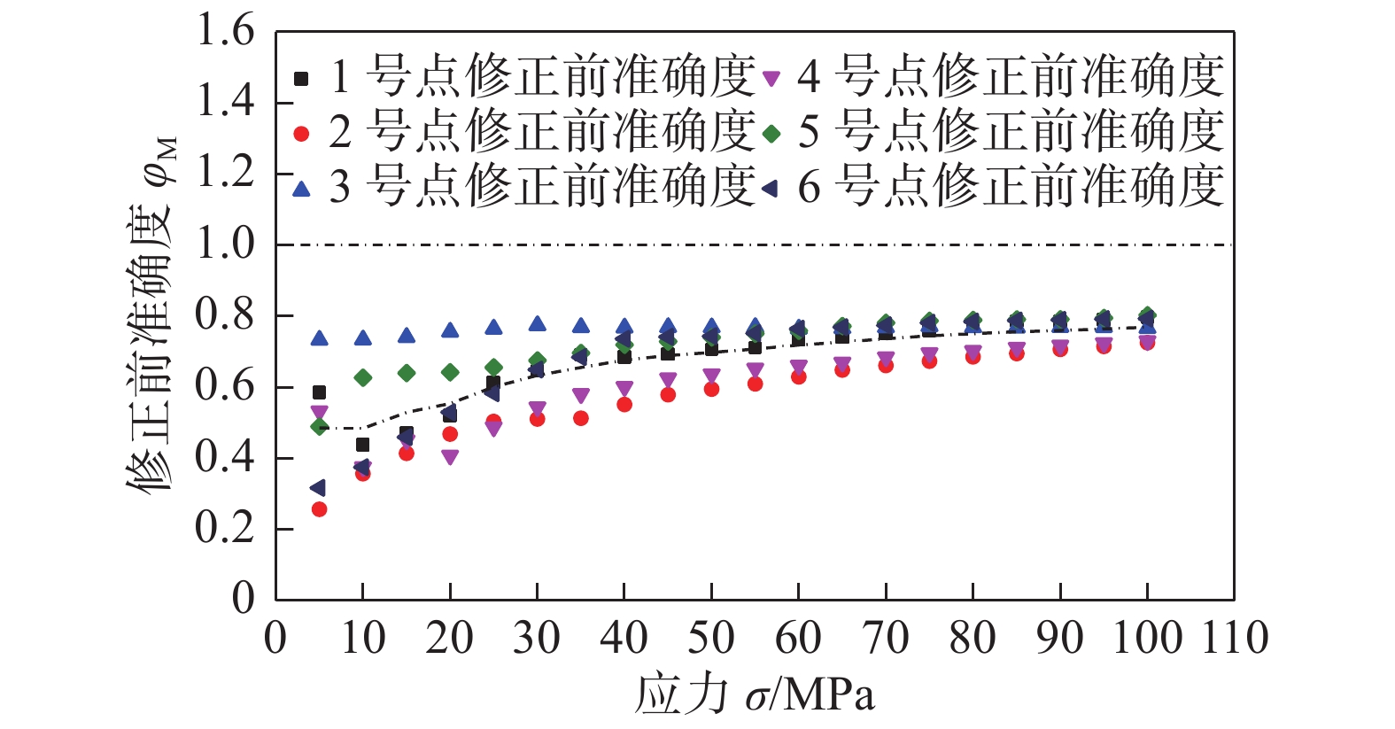
偏差S5 0.59 0.26 0.73 0.53 0.49 0.32 0.49 0.18 0.37 10 0.44 0.36 0.73 0.38 0.63 0.38 0.49 0.16 0.33 15 0.47 0.41 0.74 0.45 0.64 0.46 0.53 0.13 0.25 20 0.52 0.47 0.76 0.41 0.64 0.53 0.56 0.13 0.23 25 0.61 0.50 0.77 0.49 0.66 0.58 0.60 0.10 0.17 30 0.65 0.51 0.77 0.54 0.68 0.65 0.63 0.10 0.16 35 0.69 0.51 0.77 0.58 0.70 0.69 0.66 0.09 0.14 40 0.69 0.55 0.77 0.60 0.72 0.74 0.68 0.08 0.12 45 0.69 0.58 0.77 0.63 0.73 0.74 0.69 0.07 0.10 50 0.71 0.59 0.77 0.64 0.74 0.74 0.70 0.07 0.10 55 0.71 0.61 0.77 0.65 0.75 0.75 0.71 0.06 0.08 60 0.73 0.63 0.77 0.66 0.76 0.77 0.72 0.06 0.08 65 0.74 0.65 0.77 0.67 0.77 0.77 0.73 0.05 0.07 70 0.75 0.66 0.77 0.69 0.78 0.77 0.74 0.05 0.07 75 0.76 0.67 0.77 0.70 0.79 0.78 0.75 0.05 0.07 80 0.78 0.69 0.77 0.70 0.79 0.79 0.75 0.04 0.05 85 0.79 0.70 0.77 0.71 0.79 0.79 0.76 0.04 0.05 90 0.79 0.71 0.77 0.72 0.79 0.79 0.76 0.04 0.05 95 0.79 0.72 0.77 0.72 0.80 0.79 0.77 0.04 0.05 100 0.80 0.73 0.77 0.73 0.80 0.79 0.77 0.03 0.04 注:文中测量值准确度为测量读数除以理论值无量纲化处理后保留百分位结果,下同. 表中φiP(i = 1, 2, 3……)为第i个测试点的准确度. 表 6 试验序号47 ~ 64的测量结果数据
Table 6 Measurement results of experiment No. 47 to 64
压力Fy/N 压应力理论值σy/MPa 1组读数 2组读数 3组读数 4组读数 5组读数 6组读数 −5.4 −0.1 — — — — — — −27 −0.5 — — — — — — −54 −1 −3.649 1 −4.700 9 −4.230 8 −2.784 4 −3.403 9 −3.726 8 表 7 试验序号65 ~ 172的测量结果数据
Table 7 Measurement result of experiment No. 65 to 172
压力Fy/N 压应力理论值σy/MPa σ1MG/MPa σ2MG/MPa σ3MG/MPa σ4MG/MPa σ5MG/MPa σ6MG/MPa −270 −5 −12 −14 −12 −10 −12 −11 −540 −10 −16 −20 −18 −16 −21 −18 −810 −15 −20 −23 −22 −20 −25 −22 −1080 −20 −23 −27 −25 −24 −29 −26 −1350 −25 −28 −31 −29 −28 −33 −30 −1620 −30 −32 −35 −32 −32 −37 −33 −1890 −35 −36 −38 −36 −36 −40 −37 −2160 −40 −41 −43 −40 −41 −44 −42 −2430 −45 −45 −47 −45 −45 −48 −46 −2700 −50 −49 −51 −49 −49 −51 −50 −2970 −55 −53 −55 −54 −54 −55 −54 −3240 −60 −57 −59 −57 −58 −60 −58 −3510 −65 −62 −63 −62 −62 −63 −63 −3780 −70 −66 −67 −65 −66 −67 −66 −4050 −75 −70 −71 −70 −72 −71 −70 −4860 −90 −81 −81 −80 −82 −83 −81 −5670 −105 −92 −93 −92 −96 −95 −94 −6480 −120 −106 −106 −105 −109 −110 −108 注:表中σiMG (i = 1, 2, 3……)为第i组测试点的应力测量值,下标中的G表示组的含义,表8中准确度含义相同. 表 8 试验序号65 ~ 172的测量结果准确度
Table 8 Accuracy of measurement results of experiment No. 65 to 172
内应力理论值s/MPa φ1G φ2G φ3G φ4G φ5G φ6G 准确度平均值φAve 准确度均方差MSE 标准偏差
S−5 2.34 2.78 2.40 1.98 2.32 2.22 2.34 0.26 0.11 −10 1.64 1.99 1.79 1.55 2.13 1.87 1.83 0.22 0.12 −15 1.31 1.56 1.45 1.31 1.68 1.52 1.47 0.15 0.10 −20 1.16 1.35 1.26 1.19 1.44 1.34 1.29 0.11 0.09 −25 1.13 1.23 1.14 1.12 1.33 1.22 1.20 0.08 0.07 −30 1.05 1.16 1.07 1.07 1.22 1.13 1.12 0.07 0.06 −35 1.04 1.10 1.03 1.03 1.15 1.08 1.07 0.05 0.05 −40 1.03 1.07 1.00 1.01 1.09 1.07 1.05 0.04 0.04 −45 1.01 1.04 0.99 1.00 1.06 1.04 1.02 0.03 0.03 −50 0.99 1.02 0.98 0.97 1.02 1.00 1.00 0.02 0.02 −55 0.97 1.00 0.98 0.98 1.01 0.99 0.99 0.01 0.01 −60 0.96 0.98 0.96 0.97 0.99 0.98 0.97 0.01 0.01 −65 0.95 0.98 0.95 0.95 0.97 0.98 0.96 0.01 0.01 −70 0.94 0.96 0.93 0.94 0.95 0.95 0.95 0.01 0.01 −75 0.94 0.95 0.93 0.95 0.95 0.94 0.94 0.01 0.01 −90 0.90 0.90 0.89 0.91 0.92 0.90 0.90 0.01 0.01 −105 0.87 0.89 0.87 0.91 0.91 0.90 0.89 0.02 0.02 −120 0.88 0.88 0.88 0.91 0.92 0.90 0.90 0.02 0.02 表 9 偏心距离与等效直径统计
Table 9 Eccentricity distance and equivalent diameter
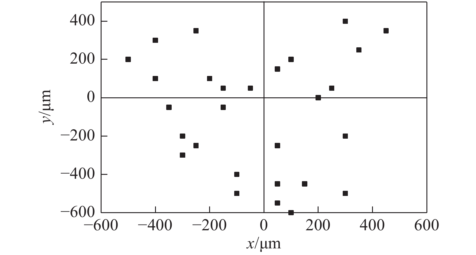
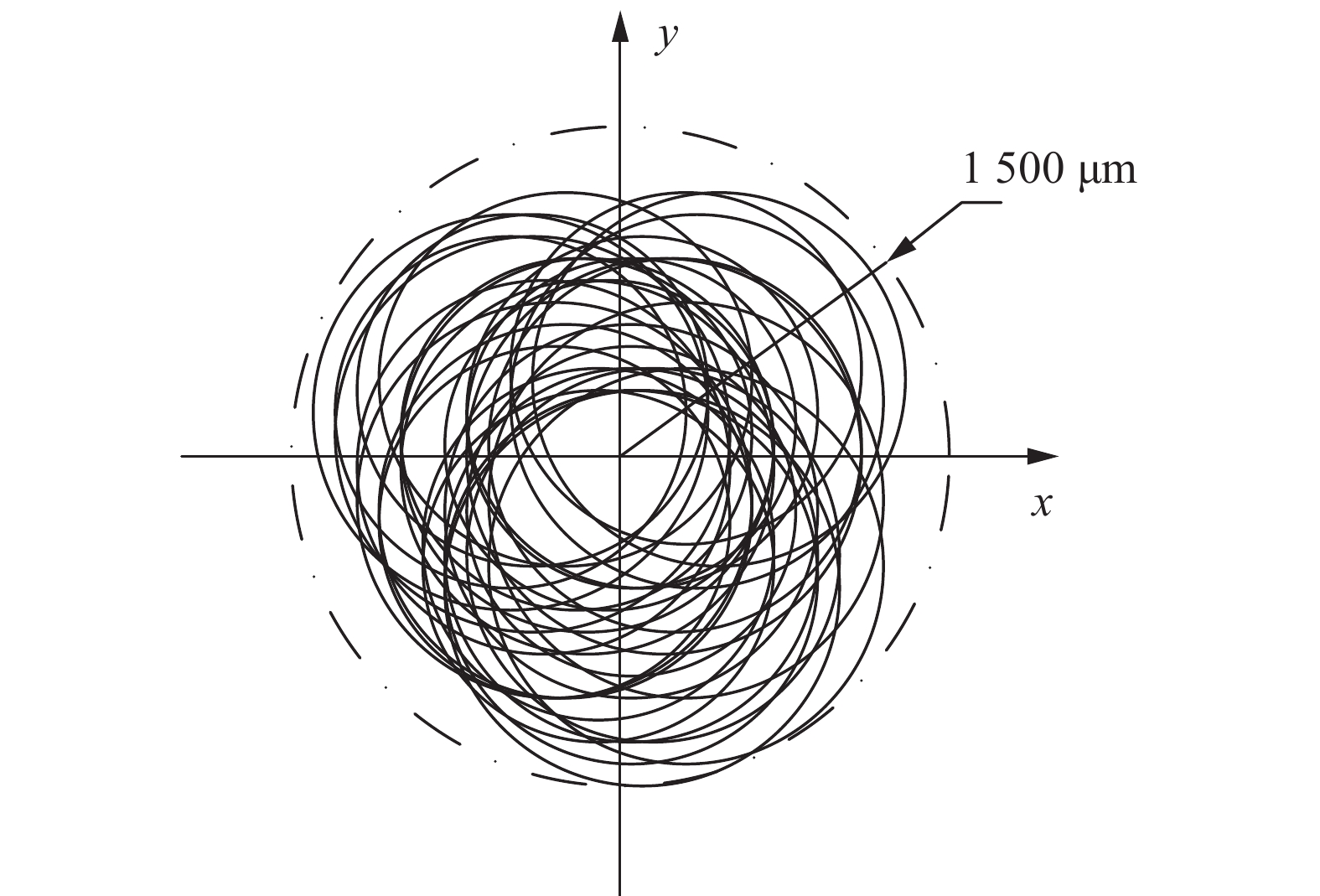
编号 x方向偏离量∆x/μm y方向偏离量∆y/μm 等效直径DE/μm 1 −50 50 1500 2 50 150 1500 3 −100 −500 1600 4 50 −250 1500 5 50 −550 1700 6 −300 −300 1600 7 −400 300 1600 8 250 50 1700 9 −350 −50 1700 10 −500 200 1800 11 −200 100 1600 12 −100 −400 1600 13 50 −250 1700 14 −500 200 1600 15 350 250 1700 16 −250 350 1700 17 300 400 1600 18 450 350 1700 19 −150 −50 1700 20 −150 50 1700 21 −400 100 1800 22 −250 −250 1700 23 100 −600 1800 24 100 200 1600 25 150 −450 1700 26 50 −450 1700 27 300 −500 1800 28 −300 −200 1800 29 200 0 1800 30 300 −200 1800 表 10 辊系参数
Table 10 Roll parameter
轧辊 辊身直径
DRb/mm辊身长度
L/mm辊颈直径
DRn/mm偏心距
e/mm上辊 900 1630 700 220 下辊 500 1630 400 220 表 11 带钢参数
Table 11 Strip parameters
入口厚度H/mm 入口宽度W/mm 前张力Ff/MPa 后张力Fa/MPa 4.5 1200 10 10 -
[1] 米谷茂. 残余应力的产生和对策[M]. 北京: 机械工业出版社, 1983. Shigeru Yonetani. The generation of residual stress and countermeasures [M]. Beijing: China Machine Press, 1983.
[2] 张铁浩, 王洋, 方喜风, 等. 残余应力检测与消除方法的研究现状及发展[J]. 精密成形工程, 2017, 9(5): 122 − 127. doi: 10.3969/j.issn.1674-6457.2017.05.017 Zhang Tiehao, Wang Yang, Fang Xifeng, et al. Research status and development of residual stress detection and elimination methods[J]. Journal of Netshape Forming Engineering, 2017, 9(5): 122 − 127. doi: 10.3969/j.issn.1674-6457.2017.05.017
[3] 王楠, 罗岚, 刘勇, 等. 金属构件残余应力测量技术进展[J]. 仪器仪表学报, 2017, 38(10): 2508 − 2517. doi: 10.3969/j.issn.0254-3087.2017.10.020 Wang Nan, Luo Lan, Liu Yong, et al. Research progress on stress measurement technology for metal components[J]. Chinese Journal of Scientific Instrument, 2017, 38(10): 2508 − 2517. doi: 10.3969/j.issn.0254-3087.2017.10.020
[4] 徐春广, 宋文涛, 潘勤学, 等. 残余应力的超声检测方法[J]. 无损检测, 2014, 36(7): 25 − 31. Xu Chunguang, Song Wentao, Pan Qinxue, et al. Residual stress nondestructive testing method using ultrasonic[J]. Nondestructive Testing, 2014, 36(7): 25 − 31.
[5] 曾杰伟, 张清东, 缪存孝, 等. 透射式磁弹性带钢应力无损检测[J]. 工程科学学报, 2015, 37(S1): 12 − 17. Zeng Jiewei, Zhang Qingdong, Miao Cunxiao, et al. Stress nondestructive testing of strip steel based on transmissive magnetoelastic effect[J]. Chinese Journal of Engineering, 2015, 37(S1): 12 − 17.
[6] 段能全, 任建亮, 庞瑞强, 等. 3003铝合金X射线法表面残余应力的检测[J]. 中国表面工程, 2012, 25(6): 79 − 84. doi: 10.3969/j.issn.1007-9289.2012.06.013 Duan Nengquan, Ren Jianliang, Pang Ruiqiang, et al. Measurement of surface residual stress of 3003 aluminum alloy by X-ray diffraction[J]. China Surface Engineering, 2012, 25(6): 79 − 84. doi: 10.3969/j.issn.1007-9289.2012.06.013
[7] 沈军, 林波, 迟永刚, 等. 残余应力物理法测量技术研究状况[J]. 材料导报, 2012, 26(S1): 120 − 125. Shen Jun, Lin Bo, Chi Yonggang, et al. Research status of residual stress physical method measurement techniques[J]. Materials Review, 2012, 26(S1): 120 − 125.
[8] Mathar J. Determination of inherent stresses by measuring deformations of drilled holes[J].Archiv fur das Esenintittenwesen, 1933,6(7):2−15.
[9] 吕国坤, 陈黎卿, 陈永新, 等. 盲孔法测量残余应力试验中塑性修正的插值方法[J]. 热加工工艺, 2014, 43(9): 185 − 187. Lü Guokun, Chen Liqing, Chen Yongxin, et al. Interpolation method in plastic correction in blind Hole method for residual stress measurement[J]. Hot Working Technology, 2014, 43(9): 185 − 187.
[10] 黄超群, 李桓, 罗传光, 等. 盲孔法与压痕法测量2219铝合金熔焊焊缝残余应力的对比分析[J]. 焊接学报, 2017, 38(7): 54 − 58. doi: 10.12073/j.hjxb.20150710004 Huang Chaoqun, Li Huan, Luo Chuanguang, et al. Comparative study of blind hole method and indentation method in measuring residual stress of 2219 aluminum alloy arc-welded joint[J]. Transactions of the China Welding Institution, 2017, 38(7): 54 − 58. doi: 10.12073/j.hjxb.20150710004
[11] 丁斌彦, 曹新民. 小孔释放法测量焊接残余应力的精度分析[J]. 焊接, 1983(12): 4 − 7. Ding Binyan, Cao Xinmin. Accuracy analysis of measurement of welding residual stress by small hole release method[J]. Welding & Joining, 1983(12): 4 − 7.
[12] 谭明鹤, 王荣辉, 黄永辉. 盲孔法测残余应力中应变释放系数的修正方法[J]. 热加工工艺, 2007, 36(19): 65 − 68. doi: 10.3969/j.issn.1001-3814.2007.19.024 Tan Minghe, Wang Ronghui, Huang Yonghui. Correctional method of strain release coefficients by blind-hole technique to measure residual stress[J]. Hot Working Technology, 2007, 36(19): 65 − 68. doi: 10.3969/j.issn.1001-3814.2007.19.024
[13] 孙渊. 预应力下试验标定的盲孔法测试技术[J]. 上海电机学院学报, 2011, 14(3): 141 − 145. doi: 10.3969/j.issn.2095-0020.2011.03.001 Sun Yuan. Blind hole-driling by calibration experiment under pre-stress[J]. Journal of Shanghai Dianji University, 2011, 14(3): 141 − 145. doi: 10.3969/j.issn.2095-0020.2011.03.001
[14] 李法庭. 盲孔法应变释放系数若干影响因素的敏感性分析研究[J]. 公路交通科技(应用技术版), 2017, 13(8): 207 − 209. Li Fating. Sensitivity analysis of several influencing factors of strain release coefficient of blind hole method[J]. Journal of Guizhou University of Finance and Economics, 2017, 13(8): 207 − 209.
[15] 裴怡, 包亚峰, 唐慕尧, 等. 盲孔法测量精度的研究─—边界及孔间距的影响[J]. 焊接学报, 1994, 15(3): 191 − 196. doi: 10.3321/j.issn:0253-360X.1994.03.002 Pei Yi, Bao Yafeng, Tang Muyao, et al. Study on measurement accuracy of blind hole method--effect of boundary and hole spacing[J]. Transactions of the China Welding Institution, 1994, 15(3): 191 − 196. doi: 10.3321/j.issn:0253-360X.1994.03.002
[16] 游敏, 郑小玲, 王福德, 等. 盲孔法测定焊接残余应力适宜测试时间研究[J]. 武汉水利电力大学(宜昌)学报, 1999(1): 57 − 60. You Min, Zhen Xiaoling, Wang Fude, et al. On suitable testing time of blind hole technique for measuring residual stress[J]. Journal of China Three Gorges University (Natural Sciences), 1999(1): 57 − 60.
[17] 王娜. 中厚板焊接残余应力测试的盲孔法研究[D]. 大连: 大连理工大学, 2007. Wang Na. Research on measuring welding residual stress of plate of moderate thickness using blind-hole method[D]. Da Lian: Dalian University of Technology, 2007.
[18] 郑建毅, 庄明凤, 郑高峰, 等. 用逐层钻孔的小孔法测量非均匀残余应力[J]. 振动. 测试与诊断, 2014, 34(3): 420 − 425. Zhen Jianyi, Zhuang Mingfeng, Zhen Gaofeng, et al. Measurement of non-uniform residual stresses by incremental hole-drilling method[J]. Journal of Vibration, Measurement & Diagnosis, 2014, 34(3): 420 − 425.
[19] 陈岚树, 董军, 彭洋, 等. 用于残余应力现场检测的DIC-盲孔法研究进展[J]. 建筑钢结构进展, 2014, 16(3): 37 − 44. doi: 10.3969/j.issn.1671-9379.2014.03.007 Chen Lanshu, Dong Jun, Peng Yang, et al. An overview on field residual stress detection using DIC-Hole drilling Methodology[J]. Progress in Steel Building Structures, 2014, 16(3): 37 − 44. doi: 10.3969/j.issn.1671-9379.2014.03.007
[20] Brynk T, Romelczyk-Baishya B. Residual stress estimation based on 3D DIC displacement filed measurement around drilled holes[J]. Procedia Structural Integrity, 2018, 13: 1267 − 1272. doi: 10.1016/j.prostr.2018.12.259
[21] 陈玲玲, 杨吟飞, 何宁, 等. 基于电子散斑干涉术的残余应力测量[J]. 传感器与微系统, 2010, 29(1): 108 − 110. doi: 10.3969/j.issn.1000-9787.2010.01.034 Chen Lingling, Yang Yinfei, He Ning, et al. Residual stress measurement based on electronic speckle pattern interferometry[J]. Transducer and Microsystem Technologies, 2010, 29(1): 108 − 110. doi: 10.3969/j.issn.1000-9787.2010.01.034
[22] Pisarev V, Odintsev I, Eleonsky S, et al. Residual stress determination by optical interferometric measurements of hole diameter increments[J]. Optics and Lasers in Engineering, 2018, 110: 437 − 456. doi: 10.1016/j.optlaseng.2018.06.022
[23] Shokrieh M M, Jalili S M, Kamangar M A. An eigen-strain approach on the estimation of non-uniform residual stress distribution using incremental hole-drilling and slitting techniques[J]. International Journal of Mechanical Sciences, 2018, 148: 383 − 392. doi: 10.1016/j.ijmecsci.2018.08.035
[24] 张清东, 陈先霖, 王长松, 等. 冷轧宽带钢横向内应力分布的试测与计算[J]. 北京科技大学学报, 1994(s2): 81 − 85. Zhang Qingdong, Chen Xianlin, Wang Changsong, et al. Measurement and calculation of transversal internal stress distribution in the Off-line cold rolled strip[J]. Journal of University of Science and Technology Beijing, 1994(s2): 81 − 85.
[25] 李博, 张清东, 张晓峰. 带钢平整轧制残余应力场的二维数值模拟[J]. 轧钢, 2014, 31(1): 14 − 18. doi: 10.3969/j.issn.1003-9996.2014.01.004 Li Bo, Zhang Qingdong, Zhang Xiaofeng, et al. Two-dimensional numerical simulation of residual stress of strip in temper rolling process[J]. Steel Rolling, 2014, 31(1): 14 − 18. doi: 10.3969/j.issn.1003-9996.2014.01.004
[26] 翟传明, 邸小坛, 白伟亮, 等. 盲孔法检测既有金属结构应力的研究[J]. 建筑科学, 2011, 27(s1): 116 − 120. Zhai Chuanming, Di Xiaotan, Bai Weiliang, et al. Research on stress inspected by blind hole method in the existing metal structures[J]. Bulding Science, 2011, 27(s1): 116 − 120.


 下载:
下载:


