
Optimization of Mg-Gd-Y-Zr laser welding process parameters and study on high temperature mechanical properties
-
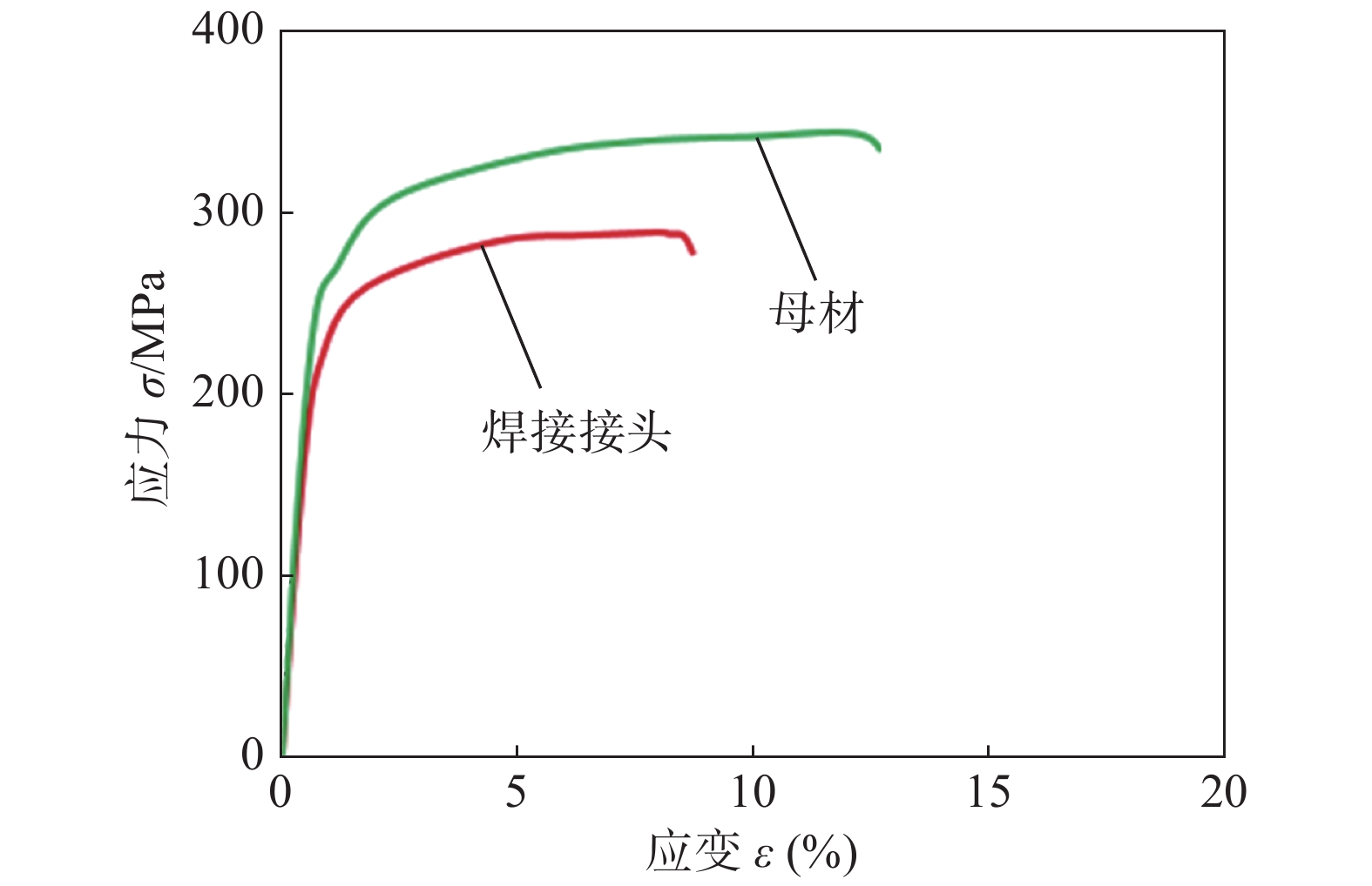
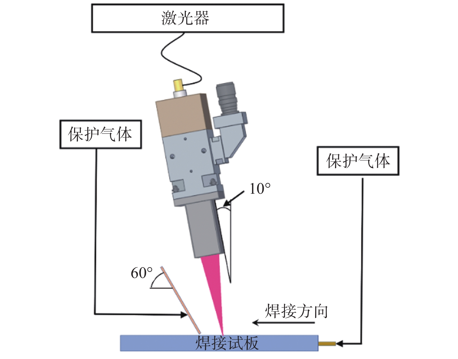
摘要: 利用光纤激光焊对T6态Mg-10Gd-3Y-0.5Zr板材进行焊接. 以高温抗拉强度为评价指标,采用正交试验对工艺参数进行优化,分析了激光功率对接头高温力学性能的影响. 利用SEM,XRD及HRTEM对最优工艺参数下接头焊缝中心组织、热影响区组织、高温拉伸断口进行观察与分析. 结果表明,激光功率对焊接接头高温力学性能影响最显著. 最优工艺参数下焊接接头200 ℃平均高温抗拉强度为292.1 MPa,为母材的84.5%,断后伸长率为8.6%,达母材的71.1%. 激光功率的变化会导致焊缝中心晶粒尺寸、热影响宽度及其晶粒尺寸和相组成发生变化,从而影响接头高温力学性能. 200 ℃下焊接试件与母材断裂模式均为韧性断裂且热影响区为接头薄弱部分.Abstract: The fiber laser welding is used to weld the T6 state Mg-10Gd-3Y-0.5Zr plate. Taking the high temperature tensile strength as the reference index. The process parameters were optimized by orthogonal test, and the influence of laser power on the high temperature mechanical properties of the joint was analyzed. The paper use SEM, XRD and HRTEM to observe and analyze the joint weld center structure, heat affected zone structure and high temperature tensile fracture. The results show that the laser power has the most significant effect on the high temperature mechanical properties of the welded joint. Under the optimal process parameters, the average high-temperature tensile strength of the welded joint is 292.1 MPa at 200 ℃, which is 84.5% of the base material. The elongation is 8.6%, which is up to 71.1% of the base material at 200 ℃. The change of laser power will affect the grain size, heat-affected width and phase composition of the weld, which will affect the high-temperature mechanical properties of the joint. The fracture modes of the welded joint and the base metal are ductile fractures at 200 ℃.The heat-affected zone is the weak part of the joint.
-
0. 序言
焊接结构疲劳评估的主S-N曲线法自提出以来,取得了很好的应用效果,该方法采用与外载荷平衡的结构应力作为参数,解决了焊接结构高周疲劳寿命预测时S-N曲线的选取困难和有限元计算时的网格敏感性问题[1-4]. 2007年针对低周疲劳问题,在ASME BPVC VIII-2标准中给出了伪弹性算法,即将疲劳试验获得的加载—位移曲线外推插值,深入的研究表明该算法是有局限性的,为解决该局限性提出了结构应变法,并推导了弯曲为主和膜应力为主的理想弹塑性材料的结构应变理论解[5]. 产品设计时要求应力低于屈服强度,故而很少存在低周疲劳问题,导致结构应变方法的应用较少[6-9].
2019年,高一迪等人[10]在国内率先在开展了等效结构应变法在低周疲劳范围的适用性研究,结果表明作为结构应力法的延伸,结构应变法可以应用到低周疲劳范围. 近年来,有些铁路货车产品出现了低周疲劳故障问题,线路测试时发现,原来认为弹性状态的构件,在运用过程中确实存在高于屈服的应力响应. 在设计前端,随着轻量化设计要求的提出,一方面结构要减重,另一方面更要充分发挥构件的潜力,所以设计也开始考虑低周疲劳设计[11]. 因此详细梳理结构应变法理论,建立分析流程,开展工程领域的适用性研究是目前亟待开展的研究工作.
鉴于此,在前期成果的基础上,推导理想弹塑性模型下结构应变计算公式,并基于理论算法开展程序的设计和验证. 基于平面应变的有限元模型和结构应变理论解进行理论的适用性分析,提出结构应变法的适用范围,实现低周疲劳的结构应变法在铁路货车上的应用,为该方法在工程领域的推广应用奠定基础.
1. 结构应变法理论
结构应变法的理论假设为:对于完全弹塑性各向同性材料,通过弹性和塑性变形后,假定沿着厚度方向上的变形仍然维持在1个平面上;其次,结构应变法理论是以平面应变状态进行考虑,焊接接头模型如图1所示,采用六面体单元进行网格划分,平板承受拉伸载荷,则焊接接头中部为平面应变状态,两侧为平面应力状态,故可将三维问题简化为平面问题,如按最危险部位考核的话,实际疲劳评估应考虑为平面应变状态.
1.1 结构应变的计算方法
将焊接接头的承载情况分为两种形式:(a)弯曲载荷较大情况,弯曲应力导致板上、下面都发生屈服;(b)膜力载荷较大情况,膜应力导致上表面发生屈服.
1.1.1 上下表面都发生屈服
对于贯穿厚度的1个截面,首先使用弹性状态的结构应力计算的方式,得到膜应力
$ {\sigma _{\text{m}}} $ 和弯曲应力$ {\sigma _{\text{b}}} $ ,两者求和后显然已经超过了屈服强度$ {S_{\text{Y}}} $ ,如图2所示.由于塑性变形原因,弹性轴发生偏移,偏移距离为
$ e $ ,弹性芯变为$ 2c $ ,内、外表面的应变分别为$ {\varepsilon _{\text{0}}} $ 和$ {\varepsilon _{\text{i}}} $ ,内外表面应变对应的结构应力分别为$ {\sigma '_{\text{O}}} $ 和$ {\sigma '_{\text{i}}} $ . 根据弹性状态和塑性状态下的力和弯矩等效,列出$$ \left\{\begin{array}{l}{\displaystyle \sum F=0,\begin{array}{cc}& {\sigma }_{\text{m}}t={S}_{\text{Y}}\left(\dfrac{t}{2}-(c-e)\right)-{S}_{\text{Y}}\left(\dfrac{t}{2}-(c + e)\right)\end{array}}\\ {\displaystyle \sum {M}_{\text{O}}=0,\begin{array}{cc}& \dfrac{{t}^{2}{\sigma }_{\text{b}}}{6}={S}_{\text{Y}}\left(\dfrac{t}{2}-(c-e)\right)\times \dfrac{1}{2}\left(\dfrac{t}{2} + (c-e)\right) + \dfrac{(2c{)}^{2}{S}_{\text{Y}}}{6} + {S}_{\text{Y}}\left(\dfrac{t}{2}-(c + e)\right)\times \dfrac{1}{2}\left(\dfrac{t}{2} + (c + e)\right)\end{array}}\end{array}\right. $$ (1) 式中:
$ {\sigma _{\text{m}}} $ 和$ {\sigma _{\text{b}}} $ 为弹性状态下计算的膜应力和弯曲应力;$ {S_{\text{Y}}} $ 为材料的屈服强度;$ P $ 为拉伸载荷,$ M $ 为弯曲载荷;$ t $ 为板厚;$ e $ 为弹性轴偏离中性层的距离;$ c $ 为发生塑性变形后的中性层与塑性区距离;$ {\varepsilon _{\text{i}}} $ 和$ {\varepsilon _{\text{0}}} $ 为内、外表面的应变;$ {\sigma '_{\text{O}}} $ 和$ {\sigma '_{\text{i}}} $ 为产生内、外表面$ {\varepsilon _{\text{i}}} $ 和$ {\varepsilon _{\text{0}}} $ 时的弹性结构应力.求解后可获得式(2)中的弹性轴偏移距离和弹性芯$$ \left\{ \begin{gathered} e = \dfrac{{{\sigma _{\text{m}}}t}}{{2{S_{\rm{Y}}}}} \\ 2c = t\sqrt {3\left[ {1 - {{\left( {\dfrac{{{\sigma _{\text{m}}}}}{{{S_{\text{Y}}}}}} \right)}^2} - \dfrac{2}{3}\dfrac{{{\sigma _{\text{b}}}}}{{{S_{\text{Y}}}}}} \right]} \\ \end{gathered} \right. $$ (2) 上述计算适用于线性硬化材料或幂硬化材料,弹性芯参数
$ 2c $ 是产生塑性变形后留下的弹性芯大小,中性轴移轴参数$ e $ 是产生塑性变形以后中性轴的偏移量. 在弹性芯参数$ 2c $ 和中性轴移轴公式$ e $ 的计算公式中包含的到$ {\sigma _{\text{m}}} $ 和$ {\sigma _{\text{b}}} $ ,两者需要通过数值分析计算得到.假设弹性核的存在占主导地位,根据材料力学的几何关系,弯曲变形的曲率为$$ \dfrac{1}{R} = \dfrac{M}{{ZI}} = \dfrac{{\dfrac{1}{2}{S_{\text{Y}}} \times c \times \dfrac{2}{3}c \times 2}}{{Z \times \dfrac{{{{(2c)}^3}}}{{12}}}} = \dfrac{{\dfrac{2}{3}{c^2}{S_{\text{Y}}}}}{{\dfrac{2}{3}Z{c^3}}} = \dfrac{{{S_{\text{Y}}}}}{{Zc}} $$ (3) 式中:
$ R $ 为弯曲的曲率半径;$ Z $ 为弹性模量;$ I $ 为惯性矩.发生塑性变性后,中性轴偏移后曲率半径也跟着变化,如图3所示.
根据图3中的变形关系,可以计算出最外层的应变
$ {\varepsilon _{\text{0}}} $ 和最内层的应变$ {\varepsilon _{\text{i}}} $ ,即$$ \begin{gathered} \dfrac{R}{{R + e + \dfrac{t}{2}}} = \dfrac{1}{{1 + 1 \times {\varepsilon _{\text{o}}}}} \Rightarrow {\varepsilon _{\text{o}}} = \dfrac{1}{R}\left(e + \dfrac{t}{2}\right) \\ \dfrac{{\dfrac{t}{2} - e}}{R} = \dfrac{{1 - (1 + {\varepsilon _{\text{i}}})}}{1} \Rightarrow {\varepsilon _{\text{i}}} = \dfrac{1}{R}\left(e - \dfrac{t}{2}\right) \\ \end{gathered} $$ (4) 再根据最外层应变和最内层应变计算膜应变和弯曲应变,即
$$ \begin{gathered} {\varepsilon _{\text{m}}} = \dfrac{{{\varepsilon _{\text{o}}} + {\varepsilon _{\text{i}}}}}{2} = \dfrac{e}{R} \\ {\varepsilon _{\text{b}}} = \dfrac{{{\varepsilon _{\text{o}}} - {\varepsilon _{\text{i}}}}}{2} = \dfrac{t}{{2R}} \\ \end{gathered} $$ (5) 式中:
$ {\varepsilon _{\text{m}}} $ 为膜应变;$ {\varepsilon _{\text{b}}} $ 为弯曲应变.获得膜应变
$ {\varepsilon _{\text{m}}} $ 和弯曲应变$ {\varepsilon _{\text{b}}} $ 后,将两者求和获得结构应变$ {\varepsilon _{\text{s}}} $ ,同等效结构应力计算方法一样,在循环载荷作用下,等效结构应变的参数为$$ \Delta {E_{\text{S}}} = \dfrac{{\Delta {\varepsilon _{\text{S}}}}}{{{t^{\tfrac{{2 - m}}{{2m}}}}I{{(r)}^{\tfrac{1}{m}}}}} $$ (6) 式中:
$ \Delta {E_{\text{s}}} $ 等效结构应变的变化范围;$ \Delta {\varepsilon _{\text{s}}} $ 为结构应变的变化范围;$ m $ 为应力强度因子的幂指数,取值为3.6;$ r $ 为弯曲应变$ {\varepsilon _{\text{b}}} $ 与结构应变$ {\varepsilon _{\text{s}}} $ 的比值;$ I(r)^{\tfrac{1}{n}} $ 为载荷比$ r $ 的无量纲函数[3].等效结构应变计算后,结合主
$ E - N $ 曲线,如表1所示,进行寿命$ N $ 计算,即表 1 主E-N曲线Table 1. Main E-N curve统计依据 试验常数 $ C $ 试验常数 $ h $ 中值 0.10868 0.3195 $ + 2\sigma $ 0.13025 ${{ - } }2\sigma$ 0.06313 $ + 3\sigma $ 0.15610 ${{ - } }3\sigma$ 0.05268 $$ \Delta {E_{\text{S}}} = C \times {N^{ - h}} $$ (7) 式中:
$ C $ 和$ h $ 为试验常数;$ N $ 为寿命.1.1.2 上表面发生屈服
当膜应力较大时,弯曲应力和膜应力只能使板的一侧发生屈服. 对于贯穿厚度的一个截面,使用弹性计算的方式,将得到
$ {\sigma _{\text{m}}} $ 和$ {\sigma _{\text{b}}} $ ,两者求和后只有外表面超过了屈服强度$ {S_{\text{Y}}} $ ,如图4所示.![]() 图 4 上表面发生屈服示意图Figure 4. Schematic diagram of yield on the upper surface relation of deformation
图 4 上表面发生屈服示意图Figure 4. Schematic diagram of yield on the upper surface relation of deformation根据弹性状态和塑性状态下的力和弯矩等效,得出
$$ \left\{\begin{array}{l}{\displaystyle \sum F=0,\begin{array}{cc}& {\sigma }_{\text{m}}t={S}_{\text{Y}}\left(\dfrac{t}{2}-(c-e)\right)\end{array}}\\ {\displaystyle \sum {M}_{\text{O}}=0,\begin{array}{cc}& \dfrac{{t}^{2}{\sigma }_{\text{b}}}{6}={S}_{\text{Y}}\left(\dfrac{t}{2}-(c-e)\right)\times \dfrac{1}{2}\left(\dfrac{t}{2} + (c\text{ + }e)\right) + \dfrac{(2c{)}^{2}{S}_{\text{Y}}}{6}\end{array}}\end{array}\right. $$ (8) 经计算后,获得中性轴和弹性核,即
$$ \begin{split} & e = \dfrac{1}{8}\dfrac{{{S_{\text{Y}}}t{{\left( { - 3{\sigma _{\text{m}}} - {\sigma _{\text{b}}} + 3{S_{\text{Y}}}} \right)}^2}}}{{{{\left( { - {\sigma _{\text{m}}} + {S_{\text{Y}}}} \right)}^3}}} - \dfrac{1}{2}\dfrac{{\left( { - 2{\sigma _{\text{m}}} - {\sigma _{\text{b}}} + 2{S_{\text{Y}}}} \right)t}}{{ - {\sigma _{\text{m}}} + {S_{\text{Y}}}}} \\& c = \dfrac{t}{2}\left( {\dfrac{{ - 3{\sigma _{\text{m}}} - {\sigma _{\text{b}}} + 3{S_{\text{Y}}}}}{{ - {\sigma _{\text{m}}} + {S_{\text{Y}}}}}} \right) \end{split} $$ (9) 根据材料力学的几何关系,弯曲变形的曲率为
$$ \dfrac{1}{R} = \dfrac{{8{{({S_{\text{Y}}} - {\sigma _{\text{m}}})}^3}}}{{tE{{(3{S_{\text{Y}}} - 3{\sigma _{\text{m}}} - {\sigma _{\text{b}}})}^2}}} $$ (10) 根据曲率公式,计算外表面和内表面的应变为
$$ \begin{gathered} {\varepsilon _{\text{o}}} = \dfrac{{{S_{\text{Y}}}}}{E} + \dfrac{{(t - c)}}{R} \\ {\varepsilon _{\text{i}}} = \dfrac{{{S_{\text{Y}}}}}{E} - \dfrac{c}{R} \\ \end{gathered} $$ (11) 膜应变和弯曲应变、等效结构应变计算公式与式(5)、式(6)一致,寿命计算如式(7)所示. 用有效的屈服应力
$ {S'_{\text{Y}}} $ 替换上述公式中材料的屈服强度$ {S_{\text{Y}}} $ 为$$ {S'_{\text{Y}}} = \dfrac{{{S_{\text{Y}}}}}{{\sqrt {1 - \nu + {\nu ^2}} }} $$ (12) 式中:
$ \nu $ 为泊松比.式(12)将上述公式扩展到平面应变问题. 如果使用冯米塞斯准则,可用下式的
$ E' $ 替换$ E $ .$$ E' = \dfrac{E}{{1 - {\nu ^2}}} $$ (13) 1.1.3 结构应变法的计算实施流程
在弯曲为主的加载式(1)中,将弯矩等效整理后为
$$ {\sigma _{\text{b}}} = \dfrac{{6{S_{\text{Y}}}}}{{{t^2}}}\left[\dfrac{{{t^2}}}{4} - \dfrac{{{c^2}}}{3} - \dfrac{{\sigma _{\text{m}}^2{t^2}}}{{4S_{\text{Y}}^2}}\right]\left( {0 \leqslant c \leqslant \dfrac{t}{2} - e} \right) $$ (14) 如图2所示,当
$ c = 0 $ 时,整个截面均达到塑性,求解式(14),得$$ {\sigma _{{\text{bmax}}}} = \dfrac{{6{S_{\text{Y}}}}}{{{t^2}}}\left[\dfrac{{{t^2}}}{4} - \dfrac{{\sigma _{\text{m}}^2{t^2}}}{{4S_{\text{Y}}^2}}\right] = \dfrac{3}{2}{S_{\text{Y}}}\left[ {1 - \dfrac{{\sigma _{\text{m}}^2}}{{S_{\text{Y}}^2}}} \right] $$ (15) 如图4所示,当
$ c = 0.5t - e $ 时,仅截面一侧发生塑性变形,求解式(14),得$$ \begin{split} {\sigma _{{\text{bmin}}}}& = \dfrac{{6{S_{\text{Y}}}}}{{{t^2}}}\left[\dfrac{{{t^2}}}{4} - \dfrac{1}{3}{\left(\dfrac{t}{2} - e\right)^2} - \dfrac{{\sigma _{\text{m}}^2{t^2}}}{{4S_{\text{Y}}^2}}\right]\\& = {S_{\text{Y}}}\left[ {1 + \dfrac{{\sigma _{\text{m}}^{}}}{{S_{\text{Y}}^{}}} - \dfrac{{2\sigma _{\text{m}}^{\text{2}}}}{{S_{\text{Y}}^2}}} \right] \end{split}$$ (16) 根据以上计算结果,以弹性计算获得结构应力
$ {\sigma _{\text{s}}} = {\sigma _{\text{m}}} + {\sigma _{\text{b}}} $ 后,整个截面存在以上几种状态:(1)当$ {\sigma _{\text{s}}} \leqslant {S_{\text{Y}}} $ 时,截面没有发生屈服;(2)当$ {\sigma _{\text{b}}} \leqslant {\sigma _{{\text{bmin}}}} $ ,且$ {\sigma _{\text{s}}}> {S_{\text{Y}}} $ 时,外表面都发生屈服;(3)当$ {\sigma _{{\text{bmin}}}} \leqslant {\sigma _{\text{b}}} \leqslant {\sigma _{{\text{bmax}}}} $ ,且$ {\sigma _{\text{s}}} > {S_{\text{Y}}} $ 时,内、外表面都发生屈服;(4)当$ {\sigma _{\text{b}}} > > {\sigma _{{\text{bmax}}}} $ 时,截面发生塑性失效. 基于上述原理程序流程如图5所示.![]() 图 5 焊接结构高、低周疲劳实施流程Figure 5. Calculation process of high and low cycle fatigue of welded structures
图 5 焊接结构高、低周疲劳实施流程Figure 5. Calculation process of high and low cycle fatigue of welded structures2. 试验验证及分析
2.1 试验验证
以Q450NQR1材料的搭接接头试样为研究对象,焊接接头尺寸示意图如图6所示,为保证试验的准确性,使用能够实现塑性应变测量的测试胶水进行应变片粘贴.应变片布置如图7所示,在距离焊趾C截面2 mm、17 mm的B截面、A截面位置的上下表面布置应变片.
![]() 图 6 焊接接头宽板试样示意图(mm)Figure 6. Schematic diagram of wide plate specimen of welded joint
图 6 焊接接头宽板试样示意图(mm)Figure 6. Schematic diagram of wide plate specimen of welded joint值得注意的是由于搭接接头产生了附加弯矩,搭接接头长度为300 mm,两端夹具的夹持长度分别为80 mm,在仿真模型上一定要考虑夹持长度. 另外,由于板的宽度和应变片尺寸限制,导致布置的测点并不在1条直线上,但由于是小试样,不会产生较大影响. 弹性加载下的应变测试结果如表2所示,由于构件焊接过程中存在焊接变形,首次加载后,构件会发生1次变形调整,卸载后再重新加载,测试结果稳定,如图8所示.根据表2中的应变测试结果,采用结构应力的方法进行应力集中系数计算. 第1次拉伸时,试验存在变形微校正,选择拉伸第2次的数据计算应力集中系数为
表 2 弹性加载下的应变测试Table 2. strain test under elastic loading载荷类型 加载次数n/次 载荷值P/kN 实测应变 ε(10−6) 1号 2号 3号 4号 5号 6号 拉伸 1 25 714 251 1342 −14 1593 45 2 25 771 198 802 112 814 122 3 25 771 197 785 115 811 123 压缩 1 10 330 −61 −320 −37 −336 −35 2 25 −859 −140 −818 −86 −852 −87 3 25 −803 −163 −790 −100 −820 −107 ![]() 图 8 焊接接头应变片布置及应变测试Figure 8. Strain gauge arrangement and strain testing of welded joints
图 8 焊接接头应变片布置及应变测试Figure 8. Strain gauge arrangement and strain testing of welded joints$$ \left\{\begin{gathered} {S_1} = 158.8\;\;{\text{MPa}},\begin{array}{*{20}{c}} {}&{{S_2} = 40.8\;\;{\text{MPa}}} \end{array} \\ {S_3} = 165.2\;\;{\text{MPa}},\begin{array}{*{20}{c}} {}&{{S_4} = 23.0\;\;{\text{MPa}}} \end{array} \\ \end{gathered}\right. $$ (17) $$ \left\{\begin{gathered} \sigma _{\text{b}}^{\text{B}} = \dfrac{1}{2}({S_1} - {S_2}) = 59.0\;\;{\text{MPa}} \\ \sigma _{\text{m}}^{\text{B}} = \dfrac{1}{2}({S_1} + {S_2}) = 99.8\;\;{\text{MPa}} \\ \sigma _{\text{b}}^{\text{A}} = \dfrac{1}{2}({S_3} - {S_4}) = 71.1\;\;{\text{MPa}} \\ \end{gathered}\right. $$ (18) $$\begin{split} \sigma _{\text{s}}^{\text{C}}& = \sigma _{\text{m}}^{\text{C}} + \sigma _{\text{b}}^{\text{C}} = \sigma _{\text{m}}^{\text{A}} + \sigma _{\text{b}}^{\text{A}} + \dfrac{{17}}{{15}}(\sigma _{\text{b}}^{\text{B}} - \sigma _{\text{b}}^{\text{A}})\\& { = {S_1}} + \dfrac{{17}}{{15}}(\sigma _{\text{b}}^{\text{B}} - \sigma _{\text{b}}^{\text{A}}) \\ &{ = 158.8 + } \dfrac{{17}}{{15}}(71.1 - 59.0)\\&{ = 172.54\;\;{\text{MPa}}} \end{split} $$ (19) 通过
$ \sigma _{\text{s}}^{\text{C}} $ 和名义应力比值(25 kN下的名义应力为100 MPa)计算出结构应力集中系数为1.73. 通过试验机采用正弦曲线将试样加载到95 kN载荷(名义应力为380 MPa),实测的应变数据如图9所示.按实测的应力集中系数1.73,380 MPa载荷下弯矩引起的最大应力为273.6 MPa. 根据上表面屈服的结构应变的式(8) ~ 式(11)可得:上表面焊趾的微应变为2910,焊趾下表面为460. 膜应变和弯曲应变分别为1685和1225. 弹性模量E为206000,
$ m $ 为3.6,板厚$ t $ 为5 mm. 则弯曲比$ r $ ,载荷控制下$I{(r)^{\tfrac{1}{m}}} $ 和等效结构应变$ \Delta {E_{\text{s}}} $ 分别为$$ r = \dfrac{{{\varepsilon _{\text{b}}}}}{{{\varepsilon _{\text{s}}}}} = \dfrac{{1\;225}}{{2\;910}} = 0.420\;9 $$ (20) $$ I{(r)^{\tfrac{1}{m}}} = \dfrac{{1.23 - 0.364r - 0.17{r^2}}}{{1.007 - 0.306r - 0.178{r^2}}} = 1.236\;2 $$ (21) $$ \Delta {E_s} = \dfrac{{\Delta {\varepsilon _s}}}{{{t^{\tfrac{{2 - m}}{{2m}}}}I{{(r)}^{\tfrac{1}{m}}}}} = \dfrac{{2\;910}}{{0.699\;3 \times 1.236\;2}} = 3\;366 $$ (22) 根据式(7)计算了该试样在不同统计值下的寿命,并与疲劳试验结果进行了对比,结果如表3所示. 可见,中值下的低周疲劳寿命计算结果与试验值吻合.
表 3 寿命计算Table 3. Life calculation寿命计算值(次) 寿命试验值
(次)中值 ( + 2σ) (−2σ) ( + 3σ) (−3σ) 34780 149984 8065 646779 1870 24201 2.2 适用性分析
建立的平面应变有限元模型如图10所示,模型一端施加对称约束,另一端施加膜应力和弯曲应力载荷,在靠近对称约束位置,建立路径,路径的起点和终点如图10所示.
理论算法和平面应变的有限元模型对比如图11所示. 固定端的膜应力载荷
$ {\sigma _{\text{m}}} $ 取为250 MPa,300 MPa,350 MPa和380 MPa,通过改变端部弯曲应力载荷,计算不同弯曲应力载荷下平面应变模型和结构应变理论解对比如图11(a) ~ 图11(d)所示.![]() 图 11 理论算法和平面应变的有限元模型对比Figure 11. Comparison between theoretical algorithm and plane strain finite element model. (a) the membrane stress is 250 MPa; (b) the membrane stress is 300 MPa; (c) the membrane stress is 350 MPa; (d) the membrane stress is 380 MPa; (e) the bending stress is 250 MPa; (f) the bending stress is 325 MPa
图 11 理论算法和平面应变的有限元模型对比Figure 11. Comparison between theoretical algorithm and plane strain finite element model. (a) the membrane stress is 250 MPa; (b) the membrane stress is 300 MPa; (c) the membrane stress is 350 MPa; (d) the membrane stress is 380 MPa; (e) the bending stress is 250 MPa; (f) the bending stress is 325 MPa固定端的弯曲应力载荷
$ {\sigma _b} $ 取250 MPa、325 MPa,通过改变端部膜应力载荷,计算不同膜应力载荷. 平面应变模型和结构应变理论解对比如图11(e)、图11(f)所示.计算结果表明:当材料的屈服为550 MPa,当弯曲载荷与膜应力载荷合载荷为700 MPa时,平面应变模型和结构应变理论解结果完全一致,高于700 MPa后,随着载荷的增加,误差也随着增加.3. 应用实例
以货车车体为研究对象,采用板壳单元建模,单元长度为30 mm,将车体考虑为柔性体,采用固定交界面法完成柔性体计算 [12-13]. 为了能够施加与实际状态更为吻合的载荷,以试验台模型作为车体仿真的边界条件[14]. 货车虚拟试验模型如图12所示.在虚拟试验台的车钩加载端,施加制动等效压缩载荷,载荷达到峰值后的车体的最大主应力云图如图13所示,主应力最大的位置集中在车体底盘,在车钩和两侧过度位置主应力集中较为严重.一般来讲,主应力与结构正应力往往有正相关的关系,因此我们根据车体最大主应力云图对关心焊缝进行筛选. 提取了如图13所示的A1和B1位置的正应力,发现A1位置明显超过Q450NQR1钢的屈服极限,B1位置与屈服极限接近,如图14所示.通过计算的节点力先计算结构应力,再根据2.1节中的计算流程计算出结构应变,对比了结构应力法和结构应变的损伤对比结果,如图15所示.
![]() 图 13 变形及最大主应力云图Figure 13. Cloud map of deformation and maximum principal stress. (a) first side of car body; (b) second side of car body
图 13 变形及最大主应力云图Figure 13. Cloud map of deformation and maximum principal stress. (a) first side of car body; (b) second side of car body![]() 图 15 基于结构应力和结构应变所得损伤对比Figure 15. Comparison of damage based on structural stress and structural strain. (a) The position of A1; (b) The position of B1
图 15 基于结构应力和结构应变所得损伤对比Figure 15. Comparison of damage based on structural stress and structural strain. (a) The position of A1; (b) The position of B1A1位置 ~ A4位置由于结构正应力超出材料比例极限较多,因此塑性变形比较明显,这导致了基于结构应变计算的车体疲劳损伤超过基于结构应力计算的车体疲劳损伤,以A1位置为例,基于结构应变计算的车体疲劳损伤比基于结构应力计算的车体疲劳损伤高2倍.而在车钩附近的B1位置 ~ B4位置,由于结构正应力超出材料屈服强度不多,因此基于结构应变计算得到疲劳损伤仅仅略大于基于结构应力计算得到的疲劳损伤.虽然近几年针对低周疲劳问题,针对更为精确的材料应力应变性能曲线,提出了更为准确的计算方法,但由于理想弹塑性材料不需要材料的力学性能曲线,所以开展的结构应变法在工程具有很大的应用价值.
4. 结论
(1)为了解决铁路货车的低周疲劳评估问题,详细梳理低周疲劳的结构应变法理论,完成了程序设计和方法的适用性验证.
(2)平面应变有限元模型和结构应变法理论解的对比结果表明,基于理想弹性性模型的结构应变方法及程序计算的Q450NQR1材料,当结构应力高出屈服强度150 MPa以内时,平面应变模型和结构应变理论解结果完全一致,超过该范围后,随着载荷的增加,误差也增加.
(3)低周疲劳的结构应变法现阶段能够满足铁路货车的设计需求,研究为该方法的工程推广应用提供了良好的技术支撑.
-
![]()
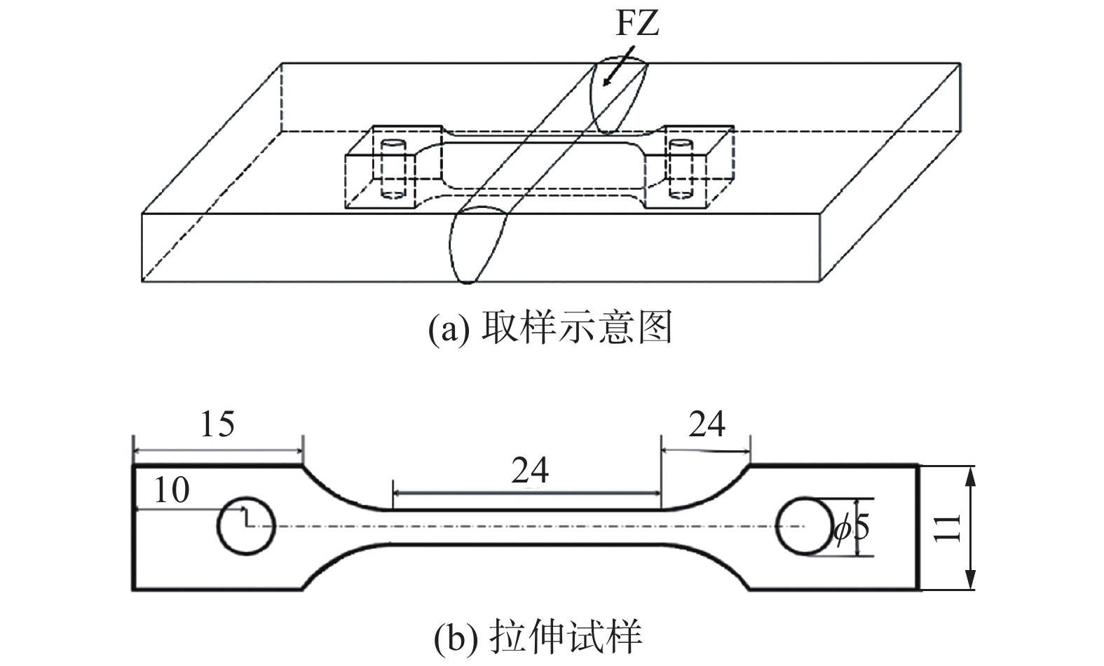
图 2 镁合金焊接接头高温拉伸试样(mm)
Figure 2. High-temperature tensile specimen of welded joint. (a) sampling diagram;(b) tensile specimen
![]()
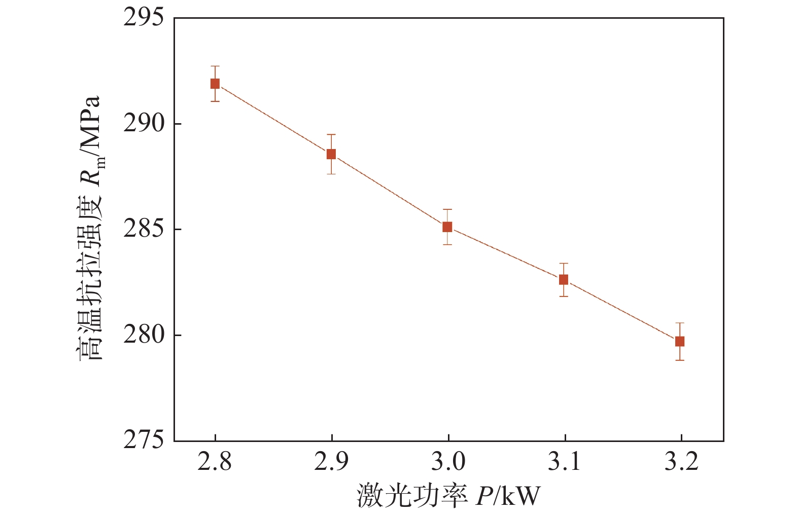
图 3 不同激光功率下焊接接头的高温力学性能
Figure 3. High temperature mechanical properties of welded joints at different laser powers
![]()
图 4 不同激光功率下焊缝中心组织SEM像
Figure 4. SEM images of weld microstructure under different laser powers. (a) 2.8 kW; (b) 3.0 kW; (c) 3.2 kW
![]()
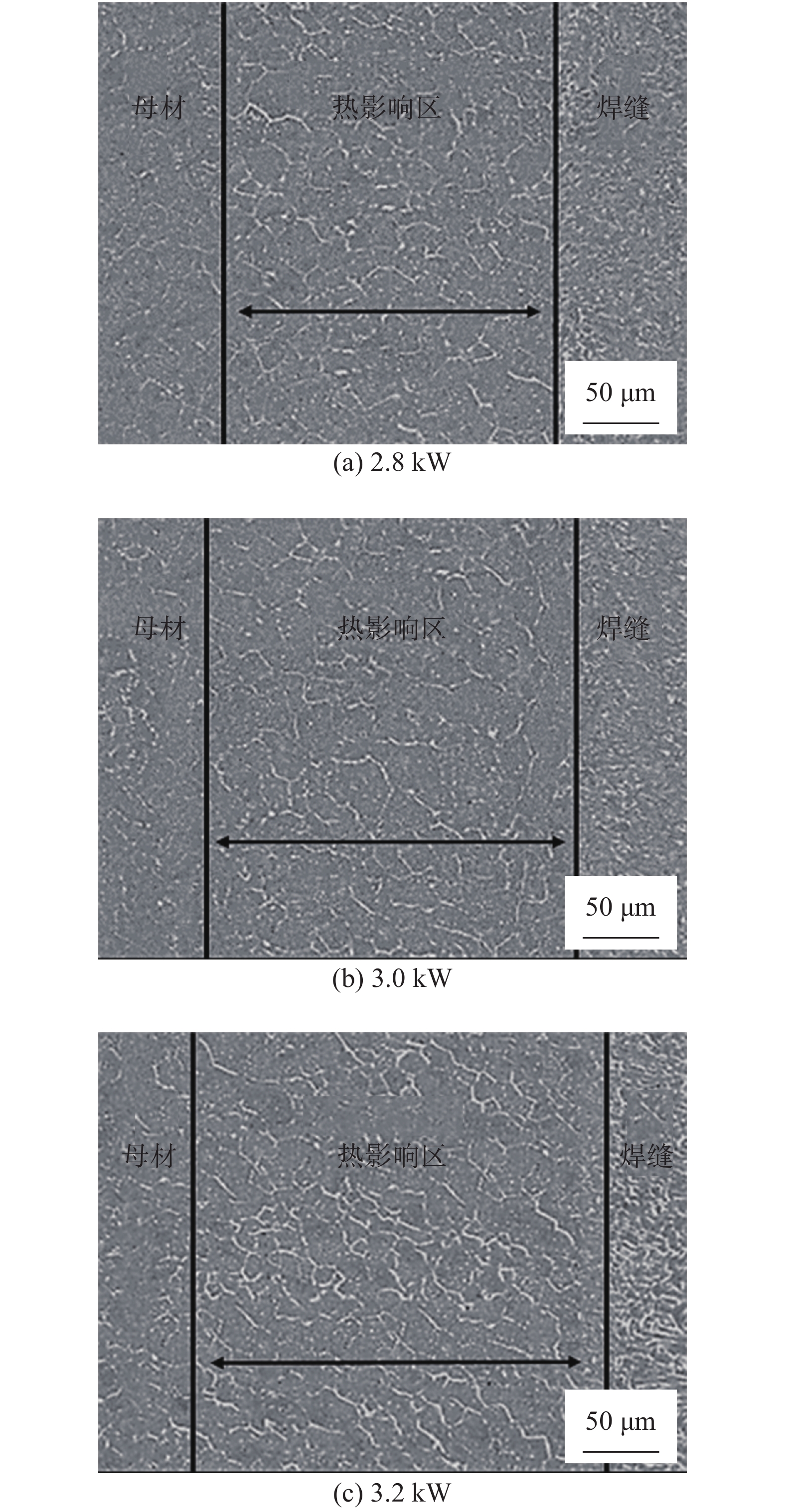
图 5 不同激光功率下热影响区的SEM像
Figure 5. SEM image of heat affected zone under different laser power. (a) 2.8 kW; (b) 3.0 kW; (c) 3.2 kW
![]()
图 6 Gd和Y在母材中的面扫描结果
Figure 6. Gd and Y distribution of base metal by area scanning. (a) base metal; (b) Gd element; (c) Y element
![]()
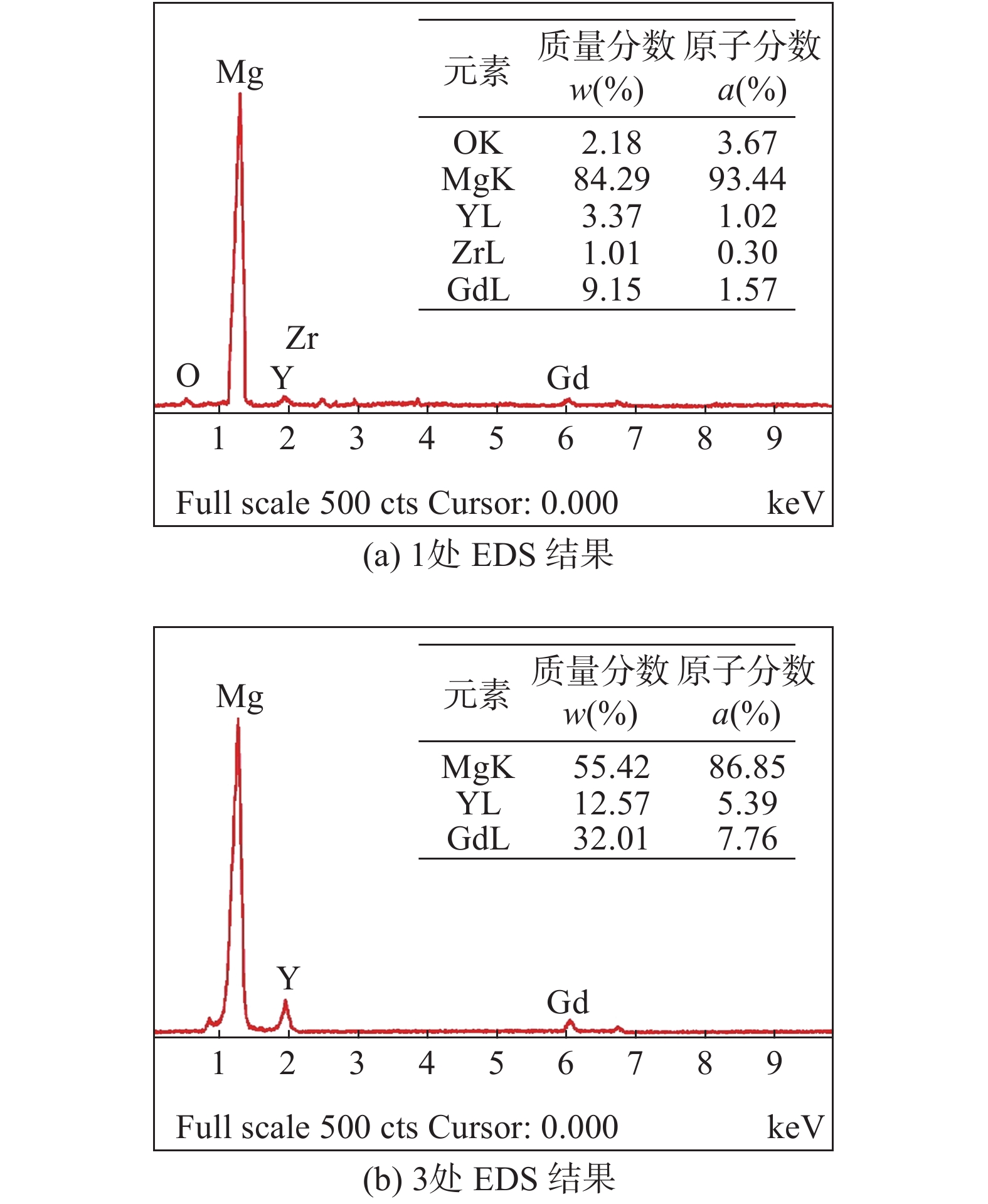
图 7 Gd和Y在焊缝中的面扫描结果
Figure 7. Gd and Y distribution of welded joint by area scanning. (a) weld center; (b) Gd element; (c) Y element
![]()
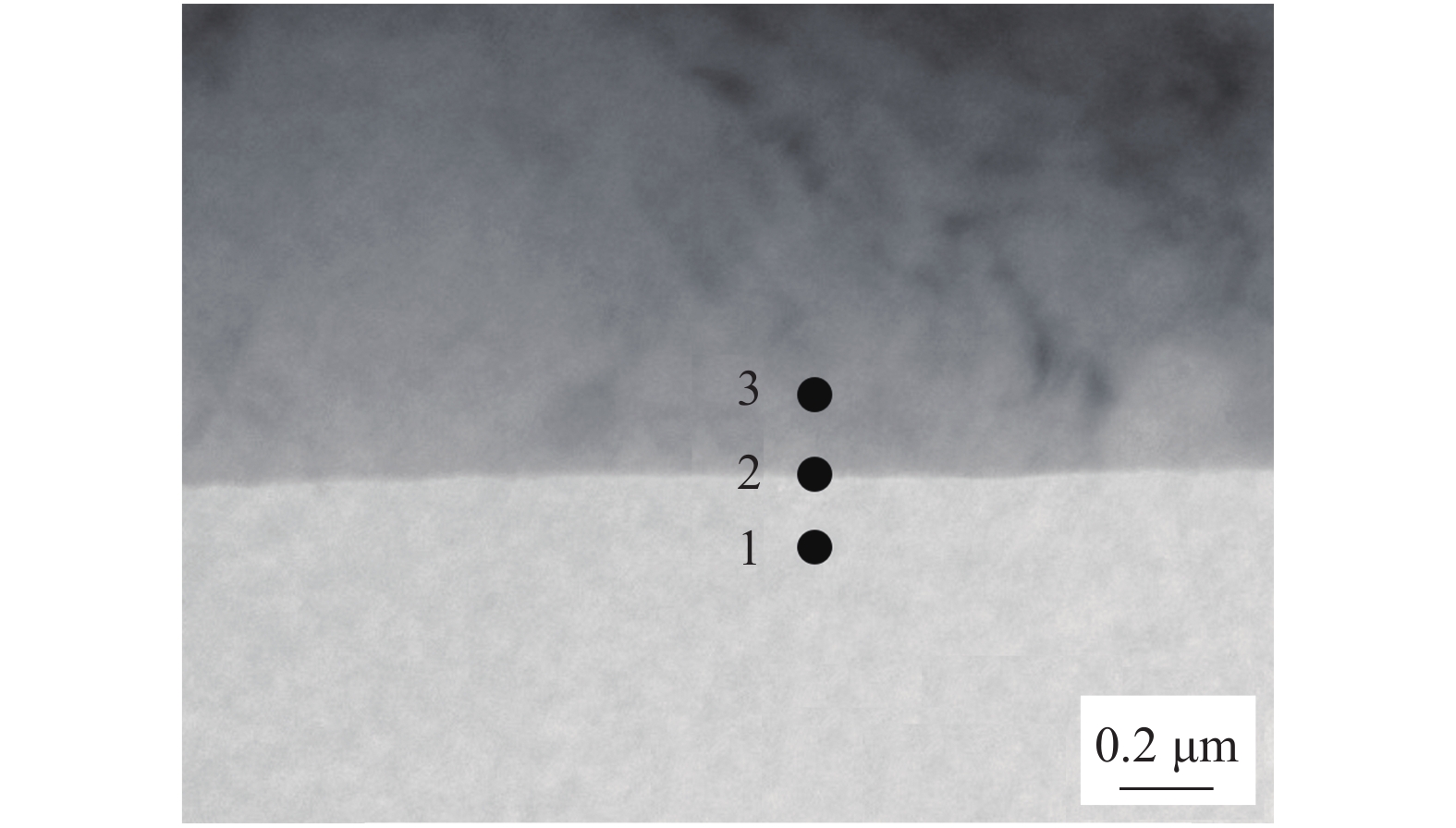
图 8 基体相与析出相及其界面处的TEM像
Figure 8. Transmission electron micrographs of the interface between the reticular precipitated phase and the matrix
![]()
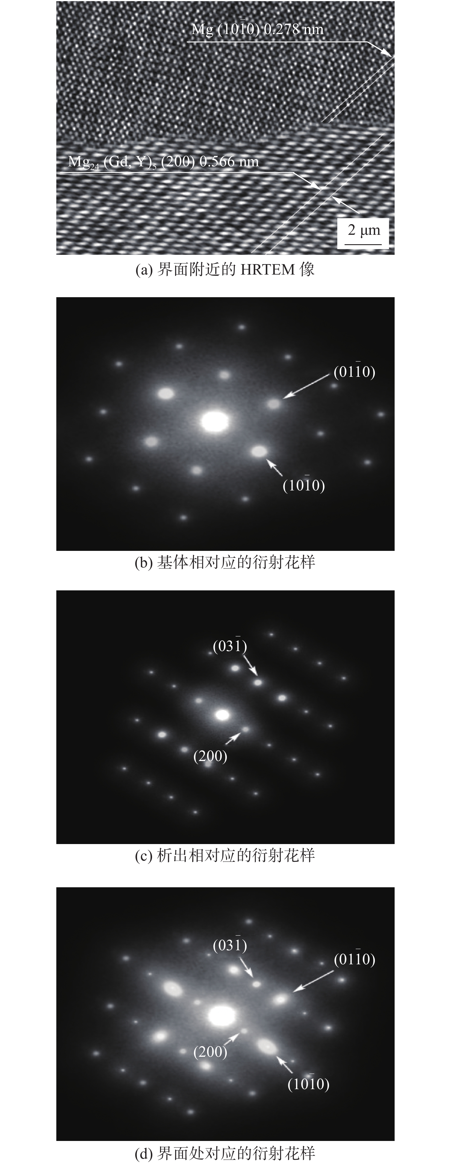
图 10 界面处的HRTEM像及SAED衍射花样
Figure 10. HRTEM images of interface between α-Mg matrix and Mg24(Gd, Y)5 precipitated phase and SAED patterns. (a) HRTEM image near the interface; (b) diffraction pattern corresponding to the substrate; (c) precipitate the corresponding diffraction pattern; (d) the corresponding diffraction pattern at the interface
![]()
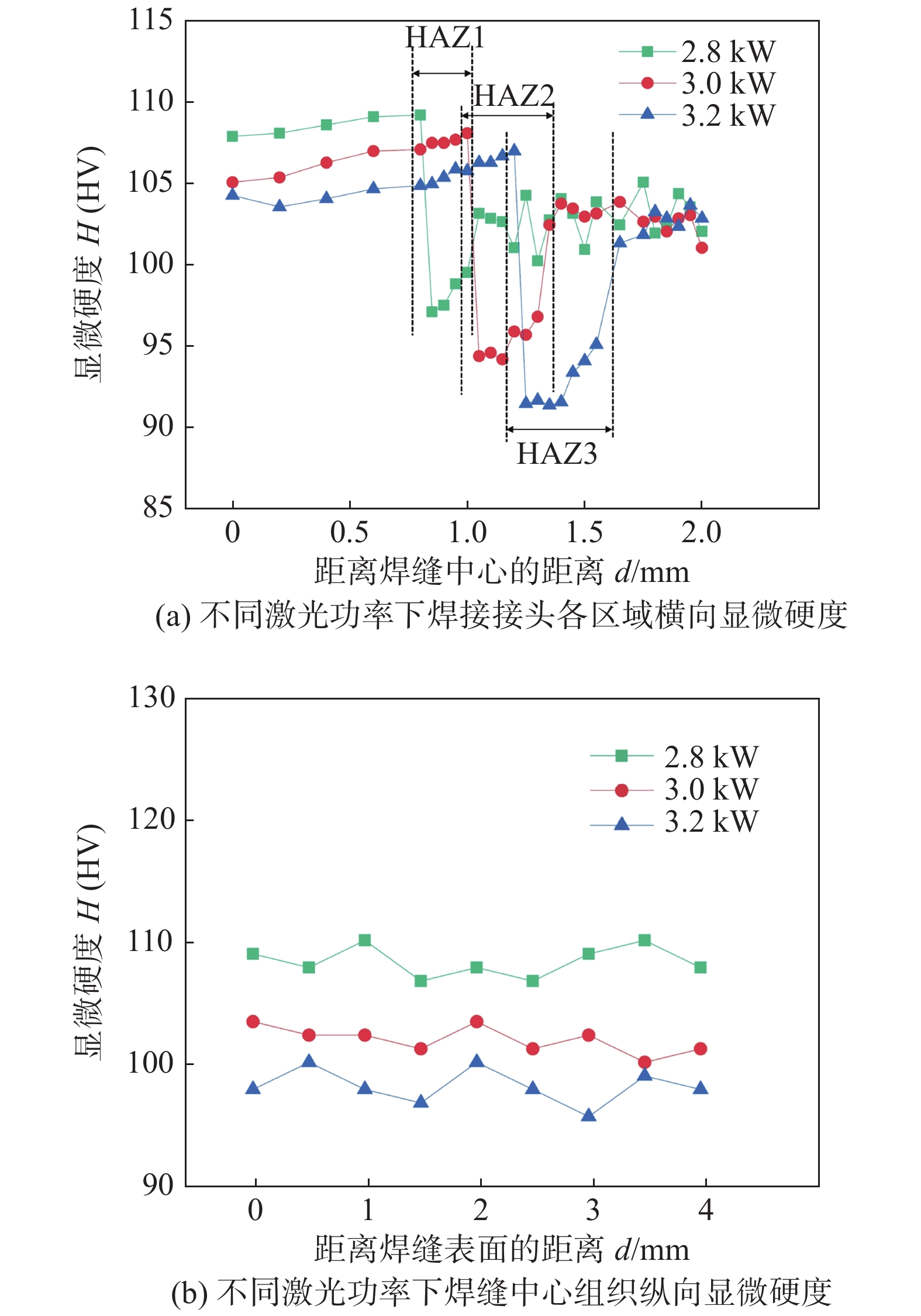
图 11 不同激光功率下焊接接头的显微硬度
Figure 11. Microhardness of welded joints under different laser powers. (a) distribution of micro-hardness across the weld joints; (b) distribution of micro-hardness of the joints in depth direction
![]()
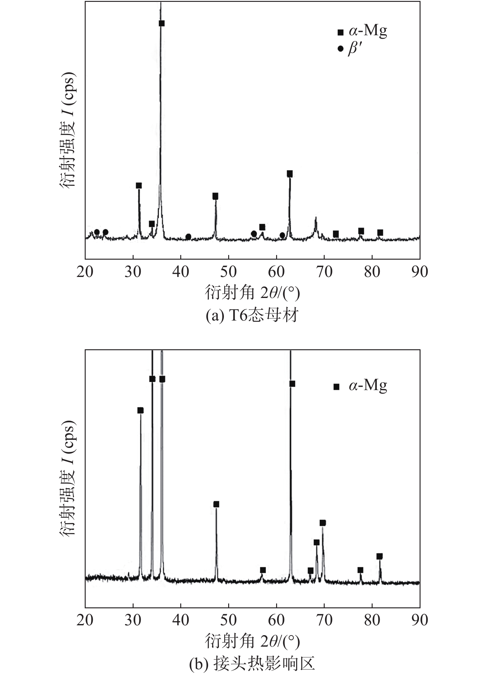
图 12 T6态母材及接头热影响区XRD衍射图谱
Figure 12. XRD diffraction pattern of T6-base metal and heat affected zone. (a) T6-base metal; (b) heat affected zone
![]()
图 13 母材与焊件200 ℃高温拉伸应力-应变曲线
Figure 13. Tensile stress-strain curve of base metal and weldment at 200 ℃
![]()
图 14 母材与焊接接头高温拉伸断口SEM像
Figure 14. SEM images of matrix and joint fracture surface. (a) base metal; (b) weld joint
表 2 工艺参数因素水平
Table 2 Factor levels of welding parameters
水平 激光功率(A)
P/kW焊接速度(B)
v/(m·min−1)离焦量(C)
f/mm1 3 2.4 −2 2 3.3 3 0 3 3.6 3.6 2  下载: 导出CSV
表 3 正交试验方案
Table 3 Orthogonal experiment scheme
序号 A B C 误差 试验方案 1 1 1 1 1 A1B1C1 2 1 2 2 2 A1B2C2 3 1 3 3 3 A1B3C3 4 2 1 2 3 A2B1C3 5 2 2 3 1 A2B2C1 6 2 3 1 2 A2B3C2 7 3 1 3 2 A3B1C2 8 3 2 1 3 A3B2C3 9 3 3 2 1 A3B3C1
下载: 导出CSV
表 4 正交试验结果
Table 4 Orthogonal experimental results
序号 激光功率(A) P/kW 焊接速度 (B) v/(m·min−1) 离焦量 (C) f/mm 误差 高温抗拉强度Rm/MPa 1 3 2.4 −2 1 256 2 3 3 0 2 278 3 3 3.6 2 3 269 4 3.3 2.4 0 3 253 5 3.3 3 2 1 262 6 3.3 3.6 −2 2 260 7 3.6 2.4 2 2 237 8 3.6 3 −2 3 242 9 3.6 3.6 0 1 259
下载: 导出CSV
表 5 极差分析表
Table 5 Range analysis table
极差 激光功率(A)
P/kW焊接速度(B)
v/(m·min−1)离焦量(C)
f/mm误差 K1j 803 746 758 777 K2j 755 782 790 775 K3j 738 788 768 762 Rj 65 42 32 15
下载: 导出CSV
表 6 方差分析表
Table 6 Variance analysis table
误差来源 偏差平方和 SA 自由度 df F值 显著水平 α 显著性 因素 A 708.67 2 22.15 0.05 高 因素 B 344.00 2 10.52 0.25 中 因素 C 178.67 2 5.46 0.25 低 误差 32.67 2 − − 总和 1 264.01 8 − −
下载: 导出CSV
表 7 焊接接头与母材高温拉伸试验结果
Table 7 High-temperature tensile test results of welded joints and base metals
位置 温度
T/℃高温抗拉强度
Rm/MPa断后伸长率
A(%)母材 200 345.6 12.3 焊接接头 200 292.1 8.6
下载: 导出CSV
-
[1] Zeng Z R, Stanford N, Davies C H J, et al. Magnesium extrusion alloys: a review of developments and prospects[J]. International Material Reviews, 2019, 64(1): 27 − 62. doi: 10.1080/09506608.2017.1421439
[2] Li W X, Wang L Y, Zhou B J, et al. Grain-scale deformation in a Mg-0.8wt% Y alloy using crystal plasticity finite element method[J]. Journal of Material Science & Technology, 2019, 35(10): 2200 − 2206.
[3] 张东阳, 王林生, 郭斗斗. 稀土镁合金性能研究及应用[J]. 材料导报, 2015, 11(29): 514 − 516. Zhang Dongyang, Wang Linsheng, Guo Doudou. Research and application of rare earth magnesium alloy[J]. Material Reports, 2015, 11(29): 514 − 516.
[4] 丁文江, 吴玉娟, 彭立明, 等. 高性能镁合金研究及应用的新进展[J]. 中国材料进展, 2010, 29(8): 37 − 45. Ding Wenjiang, Wu Yujuan, Peng Liming, et al. Research and application development of advanced magnesium alloys[J]. Material China, 2010, 29(8): 37 − 45.
[5] 鲁志龙, 张大童, 张文, 等. 不同冷却介质下多道次搅拌摩擦加工对AZ91镁合金组织和性能影响[J]. 航空材料学报, 2016, 36(36): 1: 33 − 38. Lu Zhiloong, Zhang Datong, Zhang Wen, et al. Microstructure and properties of AZ91 magnesium alloy prepared by multi-pass friction stir processing[J]. Journal of Aeronautical Material, 2016, 36(36): 1: 33 − 38.
[6] Yang Z, Li J P, Zhang Z X, et al. Review on research and development of magnesium alloys[J]. Acta Metallurgica Sinica (English Letter), 2008, 21(5): 313 − 328. doi: 10.1016/S1006-7191(08)60054-X
[7] 唐昌平, 左国良, 李志云, 等. Mg-Gd系合金的合金化研究进展[J]. 材料导报, 2018, 32(11): 3760 − 3767. Tang Changping, Zuo Guoliang, Li Zhiyun, et al. An overview on alloying research of Mg-Gd alloys[J]. Material Reports, 2018, 32(11): 3760 − 3767.
[8] Lei Z L, Bi J, Li P, et al. Melt flow and grain refining in ultrasonic vibration assisted laser welding process of AZ31B magnesium[J]. Optics and Laser Technology, 2018, 108(9): 409 − 417.
[9] 檀财旺, 李俐群, 陈彦宾, 等. AZ31B镁合金的光纤激光与CO2激光焊接特性[J]. 中国激光, 2011, 38(6): 166 − 172. Tan Caiwang, Li Liqun, Chen Yanbin, et al. Characteristics of fiber laser and CO2 laser welding AZ31B magnesium alloys[J]. Chinese Journal of Lasers, 2011, 38(6): 166 − 172.
[10] 唐舵, 王春明, 田曼, 等. SUS301L-HT不锈钢激光焊接与MIG焊接对比试验研究[J]. 中国激光, 2015, 42(7): 98 − 105. Tang Duo, Wang Chunming, Tian Man, et al. Contrasting study on quality of SUS301L-HT jointsin fiber laser welding and MIG welding[J]. Chinese Journal of Lasers, 2015, 42(7): 98 − 105.
[11] 徐良, 雷振, 杨海锋, 等. 激光—电弧复合焊接头根部特性分析[J]. 焊接学报, 2019, 40(3): 76 − 79. Xu Liang, Lei Zhen, Yang Haifeng, et al. Study on the root characteristics of laser arc hybrid welding joint[J]. Transactions of the China Welding Institution, 2019, 40(3): 76 − 79.
[12] 许飞, 陈俐, 芦伟, 等. 热输入对6A02铝合金光纤激光焊缝成形的影响[J]. 焊接学报, 2017, 38(8): 119 − 123. Xu Fei, Chen Li, Lu Wei, et al. Effect of heat input on weld appearance for fiber laser welding 6A02 aluminum alloy[J]. Transactions of The China Welding Institution, 2017, 38(8): 119 − 123.
[13] Hao K D, Wang H Z, Gao M, et al. Laser welding of AZ31B magnesium alloy with beam oscillation[J]. Journal of Material Research and Technology, 2019, 8(3): 3044 − 3053. doi: 10.1016/j.jmrt.2019.04.024
[14] Dai J, Huang J, Li Z G, et al. Effects of heat input on microstructure and mechanical properties of laser-welded Mg-rare earth alloy[J]. Journal of Materials Engineering and Performance, 2013, 22(1): 64 − 70. doi: 10.1007/s11665-012-0173-8
[15] Yan K, Su J S, Zhao Y. Microstructure and mechanical properties of the laser-welded Mg-3Nd-0.4Zr (NZ30K) magnesium alloy[J]. Optics and Laser Technology, 2017, 93(8): 109 − 117.
[16] Li T T, Song G, Zhang Z D, et al. Mechanical properties and microstructures of laser-TIG welded ME21 rare earth Mg alloy[J]. Materials, 2019, 12(13): 2188 − 2201. doi: 10.3390/ma12132188
[17] 齐欣. Mg-Gd-Y-Zr镁合金的轧制及焊接工艺研究[D]. 长沙: 湖南大学, 2013. Qi Xin. Study of rolling and welding process on Mg-Gd-Y-Zr magnesium alloy[D]. Changsha: Hunan University, 2013.
[18] Wang L Y, Huang J, Li Z G, et al. Microstructure and strengthening mechanism of fiber laser-welded high-strength Mg-Gd-Y-Zr alloy[J]. Journal of Materials Engineering and Performance, 2016, 25(10): 4506 − 4513. doi: 10.1007/s11665-016-2260-8
[19] Wang L Y, Huang J, Dong J, et al. High temperature tensile properties of laser-welded high-strength Mg-Gd-Y-Zr alloy in as-welded and heat-treated conditions[J]. Weld World, 2017, 61(2): 299 − 306. doi: 10.1007/s40194-016-0404-y
[20] 房元斌, 蹤雪梅, 张华清, 等. 基于正交试验的T形接头焊接工艺优化[J]. 焊接学报, 2017, 38(8): 45 − 49. Fang Yuanbin, Zong Xuemei, Zhang Huaqing, et al. Optimization on welding procedure of T-joint based on orthogonal test[J]. Transactions of the China Welding Institution, 2017, 38(8): 45 − 49.
[21] 陶博浩, 李红, 宋永伦, 等. 电阻点焊冷轧DP600双相钢焊接接头性能的正交试验分析[J]. 焊接学报, 2013, 34(6): 81 − 84. Tao Bojie, Li Hong, Song Yonglun, et al. Analysis of orthogonal test of properties of dual-phase DP600 steel resistance spot welded joint[J]. Transactions of the China Welding Institution, 2013, 34(6): 81 − 84.
[22] 牛济泰. 材料和热加工领域的物理模拟技术[M]. 北京: 国防工业出版社, 1999. Niu Jitai. Physical simulation in materials and hot-working[M]. Beijing: National Defense Industry Press, 1999.
[23] Yang Z, Li J P, Guo Y C, et al. Precipitation process and effect on mechanical properties of Mg–9Gd–3Y–0.6Zn–0.5Zr alloy[J]. Materials Science and Engineering A, 2007, 454(4): 274 − 280.
[24] Zhang X M, Ning Z Z, Li L, et al. Microstructures and mechanical properties of EW93 magnesium alloy with rolled-T5 temper[J]. Journal of Central South University(Science and Technology), 2011, 42(12): 3663 − 3667.
[25] 何上明. Mg-Gd-Y-Zr(-Ca)合金的微观组织演变、性能和断裂行为研究[D]. 上海: 上海交通大学, 2007. He Shangming. Study on the microstructural evolution, properties and fracture behavior of Mg-Gd-Y-Zr(Ca) alloys[D]. Shanghai: Shang Hai Jiao Tong University, 2007.
-
期刊类型引用(2)
1. 李传胜,王雷,郭糠,杨祥帆,于文晶,王利忠,王洪宝,张怀强,张英波. Mo对钛合金激光焊接接头组织性能影响研究. 电焊机. 2025(01): 73-79 .  百度学术
百度学术
2. 李海英,熊淑秋. 船用耐蚀材料激光焊接技术分析. 舰船科学技术. 2024(21): 67-70 . 百度学术
其他类型引用(0)


计量
- 文章访问数: 385
- HTML全文浏览量: 54
- PDF下载量: 20
- 被引次数: 2
