Numerical simulation of double-sided explosive welding of stainless steel/ordinary carbon steel
-
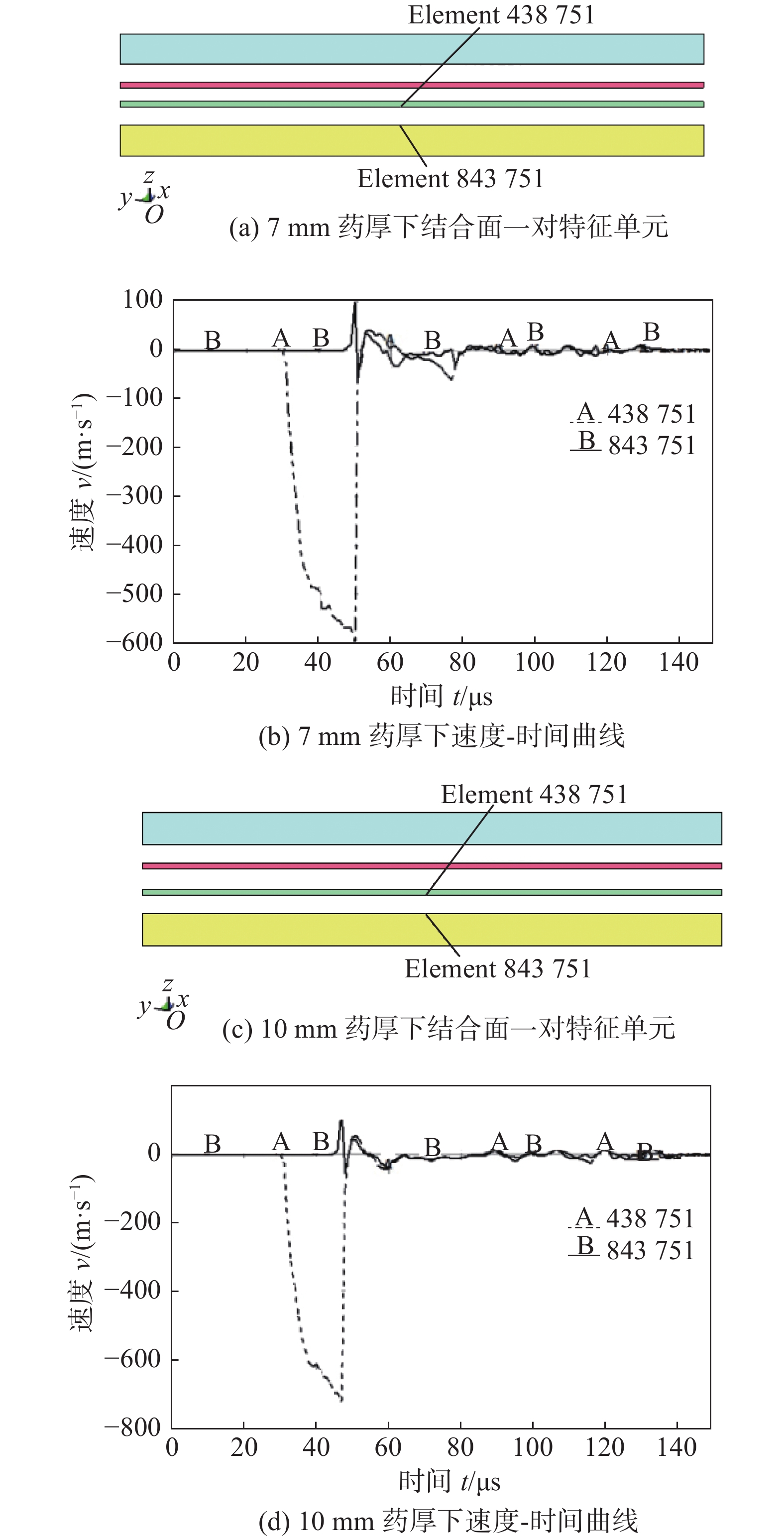
摘要: 为了提高能量的利用率,使用双面爆炸焊接装置可以一次性得到两块复合板. 借助LS-DYNA软件与光滑粒子流体动力学,采用SPH-FEM耦合算法,选取厚度为3 mm的304不锈钢、16 mm的Q235钢和乳化炸药,对不锈钢/普碳钢的双面爆炸焊接试验做了三维数值模拟,计算并建立了爆炸焊接窗口. 对模拟过程中的复板竖向位移、碰撞压力和碰撞速度进行了分析,并将模拟得到的结果与试验结果进行了比较. 模拟结果表明,7 mm药厚下复合质量较好,而10 mm药厚下可能会由于碰撞能量过大导致焊接失效,模拟与试验结果一致性较好. 引入了Gurney公式对试验结果进行预测,计算结果显示:Gurney公式的预测结果与试验结果吻合较好,表明了SPH-FEM耦合算法与Gurney公式用于不锈钢/普碳钢双面爆炸焊接的有效性.Abstract: In order to improve the utilization rate of energy, two composite plates can be obtained at one time by using a double-sided explosive welding device. With the help of LS-DYNA software and smoothed particle hydrodynamics, SPH-FEM coupling algorithm was adopted. Three-dimensional numerical simulations were made for the double-sided explosive welding experiment of stainless steel/ordinary carbon steel by selecting 304 stainless steel with the thickness of 3 mm, Q235 steel with 16 mm and emulsion explosives. The explosive welding window was calculated and established. The vertical displacement, collision pressure and collision velocity were analyzed, and the simulation results were consisted with the experimental results. The simulation results show that the composite quality is better under the thickness of 7 mm, while the welding failure may be caused by the excessive collision energy under the thickness of 10 mm. The simulation results were in accordance with the experimental results. The Gurney formula was introduced to predict the experimental results. The calculation results show that the prediction results of the Gurney formula are in good agreement with the experimental results, indicating that the SPH-FEM coupling algorithm and Gurney formula are effective for double-sided explosive welding of stainless steel/ordinary carbon steel.
-
Keywords:
- double-sided explosive welding /
- 304 steel /
- Q235 steel /
- numerical simulation
-
0. 序言
在重大装备制造中,多层多道焊(MLMPW)技术一直是重点和难点[1].MLMPW一般需要进行离线规划[1-3],但是在焊接过程中不可避免的产生偏差,如机器人姿态、焊丝偏差造成的焊道填充不均匀,以及一些常见的焊接缺陷[4-5](未熔合,未熔透,夹渣,气孔等)形成的瓶颈难题严重影响焊接质量,因此需要在焊接过程中进行实时调整.在一般情况下,实时调整的依据是通过熔深对焊缝成形进行控制,然而,从视觉传感器中能直接获取的只有正面熔池的特征几何信息,只能从正面熔池信息预测熔深.中厚板对接中的MLMPW熔池两边侧壁因为受到坡口以及已焊焊道的约束,熔池的特征信息将会有较大差异[6],不同类型的熔池对应不同的熔深进而对应不同类型的成形,从而可以对焊接过程进行较为精确的动态控制.文中主要的研究内容是通过基于视觉注意(SENet[7])模型的VGGNet[8]架构对多层多道焊接熔池进行精确分类.
1. 数据收集
1.1 试验系统和试验参数设置
文中涉及的多层多道MAG焊熔池图像数据是通过视觉传感系统采集的,如图1所示.试验系统包括Fanuc M-10iA型机器人(包括控制器和示教器),工控机,Xiris XVC-1000型高动态范围(HDR)相机(图2),Fronius TPS 400i焊接电源和保护气(80%氩气和20%二氧化碳)组成.试验母材为厚度30mm坡口为30°的Q235普通碳钢,使用直径为1.2mm的焊丝完成多层多道对接填充试验.
如图3所示,遵循先两边后中间的MLMPW顺序,通过试验探索出焊接顺序和对应的焊接参数.MLMPW的焊接方式和工艺参数如表1所示.
表 1 MLMPW参数Table 1. MLMPW parameters焊接类型 焊接速度v/(mm·min−1) 打底焊电流I1/ A 填充焊电流 I2/(A) 焊枪倾斜角θ/ (°) 气流量 q/(L·min−1) 母材尺寸L × W × H/ mm CMT 240 170 ~ 185 210 ~ 280 −15 ~ 15 20 400 × 150 × 30 1.2 试验系统和试验参数设置
如图4所示,机器人MLMPW理论模型分为三种:三角形成形、梯形成形和平行四边形成形.焊道1为三角形成形只对应于打底焊,焊道2,4,7,11,16为梯形成形,焊道3,5,6,8,9,10,12,13,14,15为平行四边形成形.细分的情况为打底焊为类型 1(T1);类型2(T2,焊道2),类型3(T3,焊道4),类型4(T4,焊道7,11,16)为梯形成形中两侧为坡口、一侧为焊道一侧为坡口和两侧为焊道的情况;类型5(T5,焊道3,5,6,8,9)、类型6(T6,焊道10,14,15)和类型7(T7,焊道12,13)为平行四边型中一侧为坡口、一侧为已经填充焊道和盖面焊的情况.
1.3 数据集增广
MLMPW熔池公开的数据集极少,为了能训练熔池分类模型,必须自建数据集.为了应对自建数据集规模较小的问题,必须丰富数据集的多样性和数量,进而对其进行数据增广,包括旋转、翻转、随机平移和缩放的组合操作.如图5所示,随机选取第四层第三道(第七道)对应的熔池作为样例,对数据增广进行展示.
![]() 图 5 熔池数据增广. 第1幅为原图,第2-6幅为翻转和顺时针旋转三次90°的图像,第7-9幅图像为随机旋转、缩放和平移组合的图像.Figure 5. Melt pool data augmentation. The first image is the original image, the second to sixth images are flipped and rotated three times 90° clockwise, and the seventh to ninth images are images with random rotation, scaling, and translation.
图 5 熔池数据增广. 第1幅为原图,第2-6幅为翻转和顺时针旋转三次90°的图像,第7-9幅图像为随机旋转、缩放和平移组合的图像.Figure 5. Melt pool data augmentation. The first image is the original image, the second to sixth images are flipped and rotated three times 90° clockwise, and the seventh to ninth images are images with random rotation, scaling, and translation.2. 模型与算法
本研究使用基于视觉注意深度学习模型对多层多道熔池进行分类.根据焊接不同的层道特性分为七种熔池模型[6].如图6所示的研究框架,通过MLMPW试验获得熔池图像并进行标记;对数据集进行增广并设定训练集和测试集.为了提高训练效率和精度,分类模型加载预训练权值到分类网络中.试验涉及四个分类模型:(1)从零开始训练VGG16网络(M1),(2)训练Pre-trained VGG16网络(M2),(3)从零开始训练SENet-VGG16网络(M3),(4)训练Pre-trained SENet-VGG16网络(M4).
2.1 VGGNet
如图7所示,VGG16是由一系列连续的3*3卷积层、2*2的池化层、三个完全连接层(FC)和Softmax输出层组成.
2.2 SENet
如图8所示,作为通道注意力机制代表的是squeeze-and-excitation network (SENet)[7],基本原理包括“挤压”(squeeze)和“激励”(excitation)两个操作,分别对特征图进行全局信息的嵌入和自适应重标定,设定不同的通道权值表达视觉注意力影响力.
2.3 迁移学习
为了应对自建数据集中数据相对较少的问题,必须引入迁移学习到MLMPW熔池分类网络中.训练数据集规模较小会引起网络欠拟合,并且从零开始训练网络时间过长,这些因素会引起网络鲁棒性较差.引入预训练模型权值到熔池分类网络中可以应对这些潜在不利因素,提升网络分类性能.
3. 结果和讨论
学习算法中的超参数的合理设定是分类网络准确与否的关键因素.如表2所示,根据试验经验设置超参数.经过训练,M1、M2、M3和M4的分类准确率为93.41%、97.73%、96.78%和98.39%,所设计的分类网络达到最优分割性能.
表 2 超参数设置Table 2. hyperparameter configuration优化算法 Momentum 学习率 损失函数 最大epochs ε Batch size SGD 0.9 0.001 cross entropy 50(eps) 8(幅图) 熔池分类网络的综合评价标准为精确率(Pr)、召回率(Re)、F1分数(F1).可表示为
$$ Pr = \frac{{{{TP}}}}{{{{TP}} + {{FP}}}} $$ (1) $$ {Re} = \frac{{{{TP}}}}{{{{TP}} + {{FN}}}} $$ (2) $$ F 1 = \frac{2 { Pr } \times { Re }}{ { Pr } + { Re }} $$ (3) 式(1) ~ 式(3)中的物理量如表3所示. TP表示预测值为1,实际值也为1;FP表示预测值为0,实际值为1;FN表示预测值为0,实际值为0;TN表示预测值为1,实际值为0.
表 3 混淆矩阵Table 3. Confusion MatrixConfusion matrix Actual value Predicted
valueTP FP FN TN 学习曲线可以可视化分类器的学习性能.网络的训练集和测试集评估模型的准确率和损失的曲线如图9所示,从Loss曲线的波动性情况来分析,所有模型的训练曲线未有波动的情况,这说明训练过程没有陷入局部极小值的情况.引入预训练权值模型的初始精度较高,高于0.85,同时初始的Loss值较低,低于0.4.
如图10所示,为进一步研究分类性能,引入混淆矩阵可视化分类性能.可以看出,多层多道熔池分类整体准确率最高的是M4,达到最高的98.39%,验证了引入SENet可提高整体分类准确率.
综合性能指标如表4所示,可以更全面的判断分类器的性能. 可以看出,除了M1之外,其他模型的精确率都在96%以上.在整体分类精度上,M4是优于其他三个模型的,特别是Type3,M4比M2高1.03%,提升较大;然而,在除了Type3和Type6外的其他类别分类性能出现了小幅度的局部退化,分类性能需再平衡优化.
表 4 熔池分类评价值(%)Table 4. Molten pool classification evaluation value模型 Type1 Type2 Type3 Type4 Type5 Type6 Type7 Pt_se_vgg16 Pr 100.00 98.69 97.58 97.02 98.14 97.07 96.46 Re 99.78 99.04 98.54 96.51 97.19 95.76 98.54 F1 99.89 98.87 98.05 96.76 97.66 96.41 97.49 se_vgg16 Pr 99.87 97.88 98.44 96.31 97.94 95.01 96.65 Re 99.74 98.54 97.35 95.92 96.31 96.19 98.12 F1 99.81 98.21 97.90 96.12 97.12 95.60 97.38 Pt_vgg16 Pr 99.96 97.86 97.90 96.93 97.97 96.53 97.29 Re 99.96 99.04 97.51 96.66 97.46 95.85 98.18 F1 99.96 98.45 97.70 96.80 97.71 96.19 97.73 vgg16 Pr 99.87 95.23 95.18 90.87 93.92 91.90 91.00 Re 99.57 97.09 93.56 91.66 93.84 87.15 94.89 F1 99.72 96.15 94.36 91.26 93.88 89.46 92.90 在所有模型中,多层多道焊Type1为打底焊,达到了近似于1的分类精度,这是因为打底焊熔池与其他层道的熔池特征差距较大。其中Type6的分类精度最低,原因是同属于平行四边形成形对应的熔池,有其相似性,区别在于Type6的熔池前端更加平滑。此时如果有弧光遮挡熔池的前端,将加剧分类的误判。验证了引入 SENet 可提高整体分类准确率.
4. 结论
(1) 为了控制MLMPW质量,开发了熔池可视化监测系统.
(2) 通过试验比较,带有视觉注意力机制的VGG16网络,训练过程通过加载预训练权值获得了整体最优的分类性能.
(3) 精确的对熔池进行分类可以避免在MLMPW过程中出现难以修复的焊道填充缺陷.
-
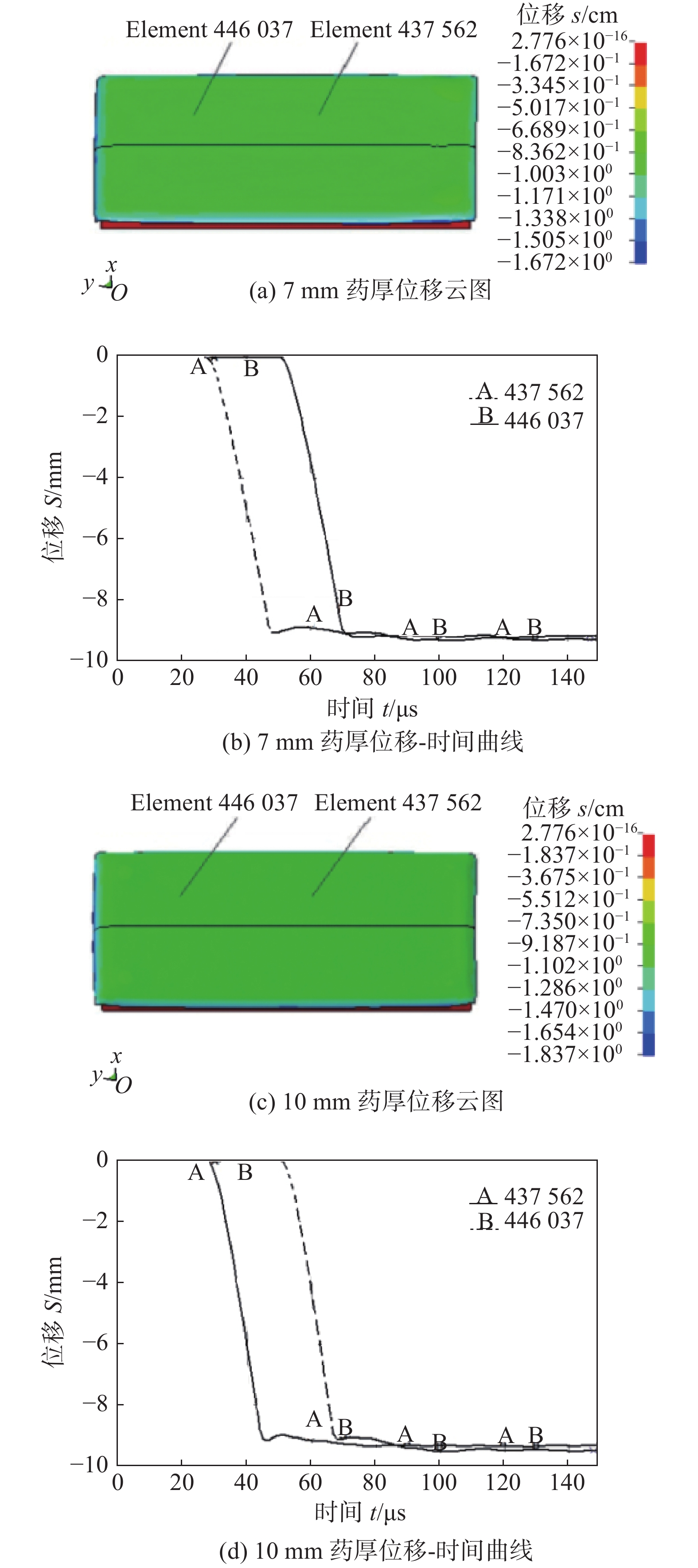
图 3 不同药厚下的竖向位移云图和位移-时间曲线
Figure 3. Vertical displacement cloud diagram and displacement-time curve under different charge thickness. (a) cloud diagram of 7 mm charge thickness; (b) displacement-time curve of 7 mm charge thickness; (c) cloud diagram of 10 mm charge thickness; (d) displacement-time curve of 10 mm charge thickness
表 1 乳化炸药的JWL状态参数
Table 1 JWL state parameters of emulsion explosive
AJWL/GPa BJWL/GPa R1 R2 ω E0/(kJ·cm−3) 326.42 5.808 9 5.80 1.56 0.57 3.323 表 2 304不锈钢和Q235钢的Johnson-Cook模型参数
Table 2 Johnson-Cook model parameters of 304 steel and Q235 steel
参数 ρ/(g·cm−3) G/GPa A B n C m Tm/K Tr/K 304不锈钢 7.9 24 0.700 1.30 0.75 0.021 0.90 1 710 294 Q235钢 7.8 77 0.792 0.51 0.26 0.014 1.03 1 809 294 表 3 304不锈钢和Q235钢的Gruneisen方程参数
Table 3 Gruneisen equation parameters of 304 steel and Q235 steel
材料 c S1 $ \gamma $ A 304不锈钢 0.458 0 1.49 1.93 0.50 Q235钢 0.456 9 1.49 2.17 0.46 表 4 304不锈钢/Q235钢材料主要性能参数
Table 4 Main performance parameters of 304 steel/Q235 steel
材料 密度ρ/(g·cm−3) 比热容Cp/(J·kg−1·K−1) 热扩散率α/(m2·s−1) 体积声速C0/(m·s−1) 厚度h/m 304不锈钢 7.9 502 3.95×10⁻⁶ 5790 0.003 Q235钢 7.8 481 2.21×10⁻⁵ 5200 0.016 表 5 7 mm药厚碰撞速度的模拟与理论计算
Table 5 Comparison of collision velocity between theoretical calculation and numerical simulation with explosive thickness of 7 mm
质量比 计算结果vcal/(m·s−1) 模拟结果vsim/(m·s−1) 误差比较(%) 0.37 787 595 32.3 表 6 10 mm药厚碰撞速度的模拟与理论计算
Table 6 Comparison of collision velocity between theoretical calculation and numerical simulation with explosive thickness of 10 mm
质量比 计算结果vcal/(m·s−1) 模拟结果vsim/(m·s−1) 误差比较(%) 0.49 898 723 24.2 -
[1] Carl L R. Brass welds, made by detonation impulse[J]. Metal Progress, 1944, 46(1): 102 − 103.
[2] 缪广红, 马宏昊, 沈兆武, 等. 不锈钢-普碳钢的双面爆炸复合[J]. 爆炸与冲击, 2015, 35(4): 536 − 540. doi: 10.11883/1001-1455(2015)04-0536-05 Miao Guanghong, Ma Honghao, Shen Zhaowu, et al. Double sided explosive cladding of stainless steel and ordinary carbon steel[J]. Explosion and Shock Waves, 2015, 35(4): 536 − 540. doi: 10.11883/1001-1455(2015)04-0536-05
[3] 缪广红, 马宏昊, 沈兆武, 等. 蜂窝结构炸药及其应用[J]. 含能材料, 2014, 22(5): 693 − 697. Miao Guanghong, Ma Honghao, Shen Zhaowu, et al. Explosives with structure of honeycomb and its application[J]. Chinese Journal of Energetic Materials, 2014, 22(5): 693 − 697.
[4] 史长根, 汪育, 徐宏. 双立爆炸焊接及防护装置数值模拟和试验[J]. 焊接学报, 2012, 33(3): 109 − 112. Shi Changgen, Wang Yu, Xu Hong. Numerical simulation and test of double vertical explosion welding and protective devices[J]. Transactions of the China Welding Institution, 2012, 33(3): 109 − 112.
[5] 史长根, 杨旋, 侯鸿宝, 等. 爆炸焊接两板间距上限法则分析与试验[J]. 焊接学报, 2018, 39(1): 1 − 4. doi: 10.12073/j.hjxb.2018390001 Shi Changgen, Yang Xuan, Hou Hongbao, et al. Analysis and experiment of the upper limit rule of the distance between two plates in explosive welding[J]. Transactions of the China Welding Institution, 2018, 39(1): 1 − 4. doi: 10.12073/j.hjxb.2018390001
[6] Shi Changgen, Sun Zerui, Fang Zhongxing, et al. Design and test of a protective structure for the double vertical explosive welding of large titanium/steel plate[J]. China Welding, 2019, 28(3): 7 − 14.
[7] Zhang Tingting, Wang Wenxian, Zhang Wei, et al. Interfacial microstructure evolution and deformation mechanism in an explosively welded Al/Mg alloy plate[J]. Journal of Materials Science, 2019, 54(12): 9155 − 9167.
[8] Feng Jianrui, Dai Kaida, Zhou Qiang, et al. Formation of bonding interface in explosive welding-a molecular dynamics approach[J]. Journal of Physics, 2019, 31(41): 415403.
[9] Bataev I A, Tanaka S, Zhou Q, et al. Towards better understanding of explosive welding by combination of numerical simulation and experimental study[J]. Materials & Design, 2019, 169: 107649.
[10] 章冠人, 陈大年. 凝聚炸药起爆动力学[M]. 北京: 国防工业出版社, 1991. Zhang Guanren, Chen Danian. Detonation dynamics of condensed explosives[M]. Beijing: National Defence Industry Press, 1991.
[11] 肖定军, 郭学彬, 蒲传金. 单孔护壁爆破数值模拟[J]. 化工矿物与加工, 2008(7): 22 − 24. doi: 10.3969/j.issn.1008-7524.2008.07.007 Xiao Dingjun, Guo Xuebin, Pu Chuanjin. Numerical simulation of single hole wall protection blasting[J]. Chemical Minerals and Processing, 2008(7): 22 − 24. doi: 10.3969/j.issn.1008-7524.2008.07.007
[12] 李裕春, 时党勇, 赵远. ANSYS11.0/LS-DYNA基础理论与工程实践[M]. 北京: 中国水利水电出版社, 2008. Li Yuchun, Shi Dangyong, Zhao Yuan. ANSYS11.0/LS-DYNA basic theory and engineering practice[M]. Beijing: China WaterPower Press, 2008.
[13] Liu G R, Liu M B. 光滑粒子流体动力学-一种无网格粒子法[M]. 韩旭译. 长沙: 湖南大学出版社, 2005. Liu G R, Liu M B. Smoothed particle hydrodynamics-a meshfree particle method[M]. Trans.Han Xu. Changsha: Hunan University Press,2005.
[14] 程国强, 李守新. 金属材料在高应变率下的热粘塑性本构模型[J]. 弹道学报, 2004, 11(6): 18 − 22. Cheng Guoqiang, Li Shouxin. Thermal viscoplastic constitutive model of metallic materials at high strain rate[J]. Journal of Ballistics, 2004, 11(6): 18 − 22.
[15] 郑远谋. 爆炸焊接和爆炸复合材料[M]. 北京: 国防工业出版社, 2017. Zheng Yuanmou. Explosive welding and explosive composite material[M]. Beijing: National Defence Industry Press,2017.
[16] 李晓杰. 双金属爆炸焊接上限[J]. 爆炸与冲击, 1991, 4(2): 134 − 138. Li Xiaojie. The upper limit of bimetal explosive welding parameters[J]. Explosion and Shock Waves, 1991, 4(2): 134 − 138.
[17] 缪广红, 李亮, 江向阳, 等. 双面爆炸焊接的数值模拟[J]. 高压物理学报, 2018, 32(4): 1 − 8. Miao Guanghong, Li Liang, Jiang Xiangyang, et al. Numerical simulation of double sided explosive welding[J]. Chinese Journal of High Pressure Physics, 2018, 32(4): 1 − 8.
[18] Saravanan S, Raghukandan K, Hokamoto K. Improved microstructure and mechanical properties of dissimilar explosive cladding by means of interlayer technique[J]. Archives of Civil and Mechanical Engineering, 2016, 16(4): 563 − 568. doi: 10.1016/j.acme.2016.03.009
[19] Nassiri A, Kinsey B. Numerical studies on high-velocity impact welding: smoothed particle hydrodynamics (SPH) and arbitrary Lagrangian-Eulerian(ALE)[J]. Journal of Manufacturing Processes, 2016(24): 376 − 381.
[20] Sui G F, Li J S. Sun F, et al 3D finite element simulation of explosive welding of three-layer plates[J]. Science China, 2011, 54(5): 890 − 896.
[21] Li Yan, Liu Cuirong, Yu Haibo, et al. Numerical simulation of Ti/Al bimetal composite fabricated by explosive welding[J]. Metals, 2017, 7(10): 407.
[22] Findik F. Recent developments in explosive welding[J]. Materials & Design, 2011, 32(3): 1081 − 1093.
[23] Mousavi A, AL-Hassani S T S. Numerical and experimental studies of the mechanism of the wavy interface formations in explosive/impact welding[J]. Journal of the Mechanics and Physics of Solids, 2005, 53(11): 2501 − 2528.
[24] 缪广红, 李亮, 江向阳, 等. 爆炸复合界面波形变化的数值模拟研究[J]. 煤矿爆破, 2017(3): 1 − 4. doi: 10.3969/j.issn.1674-3970.2017.03.001 Miao Guanghong, Li Liang, Jiang Xiangyang, et al. Numerical simulation study on waveform change of explosive composite interface[J]. Coal Mine Blasting, 2017(3): 1 − 4. doi: 10.3969/j.issn.1674-3970.2017.03.001
[25] 王耀华. 金属板材爆炸焊接研究与实践[M]. 北京: 国防工业出版社, 2007. Wang Yaohua. Research and practice of explosive welding of metal plates[M]. Beijing: National Defence Industry Press,2007.


 下载:
下载:


