
Microstructure and microhardness analysis of laser welded dissimilar steel
-
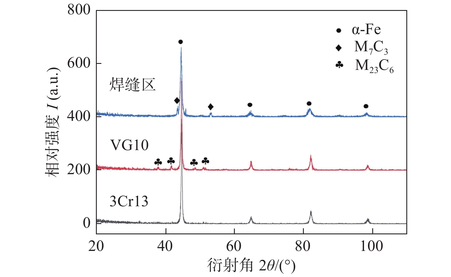
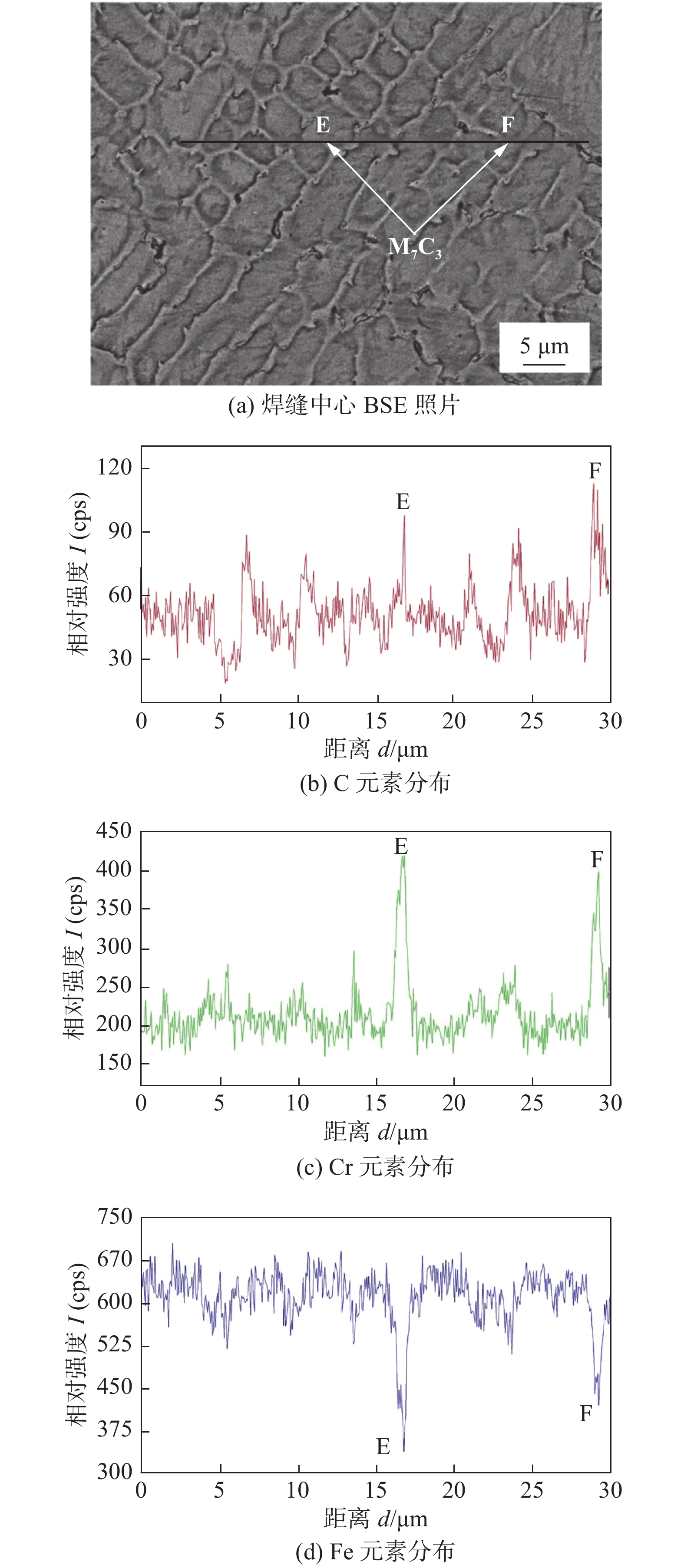
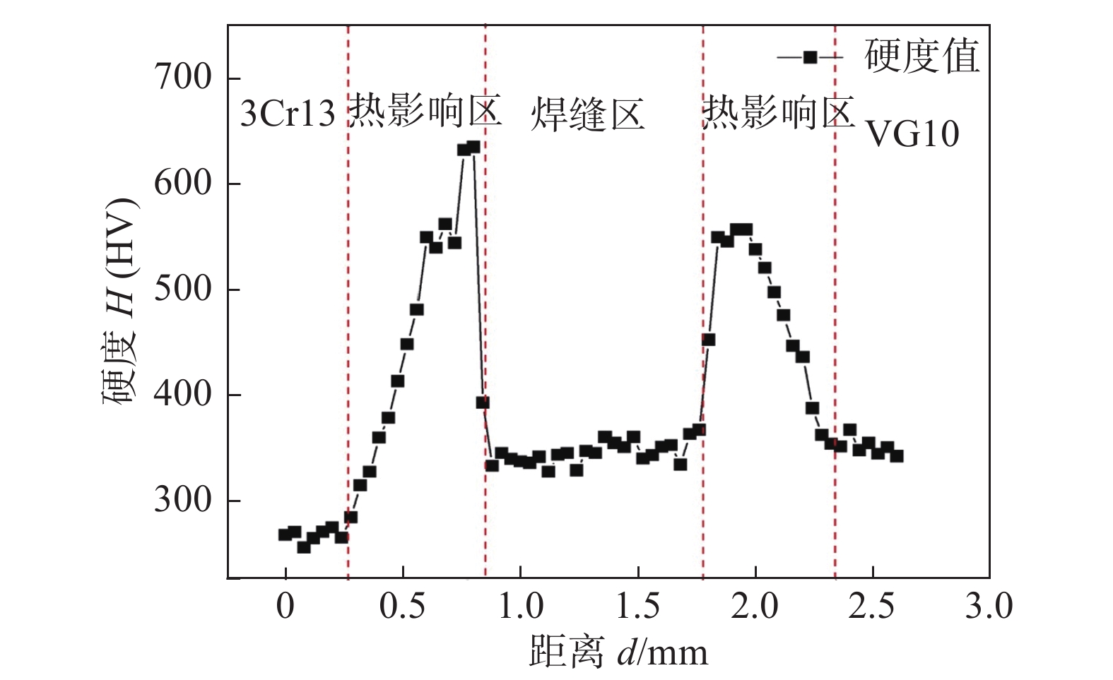
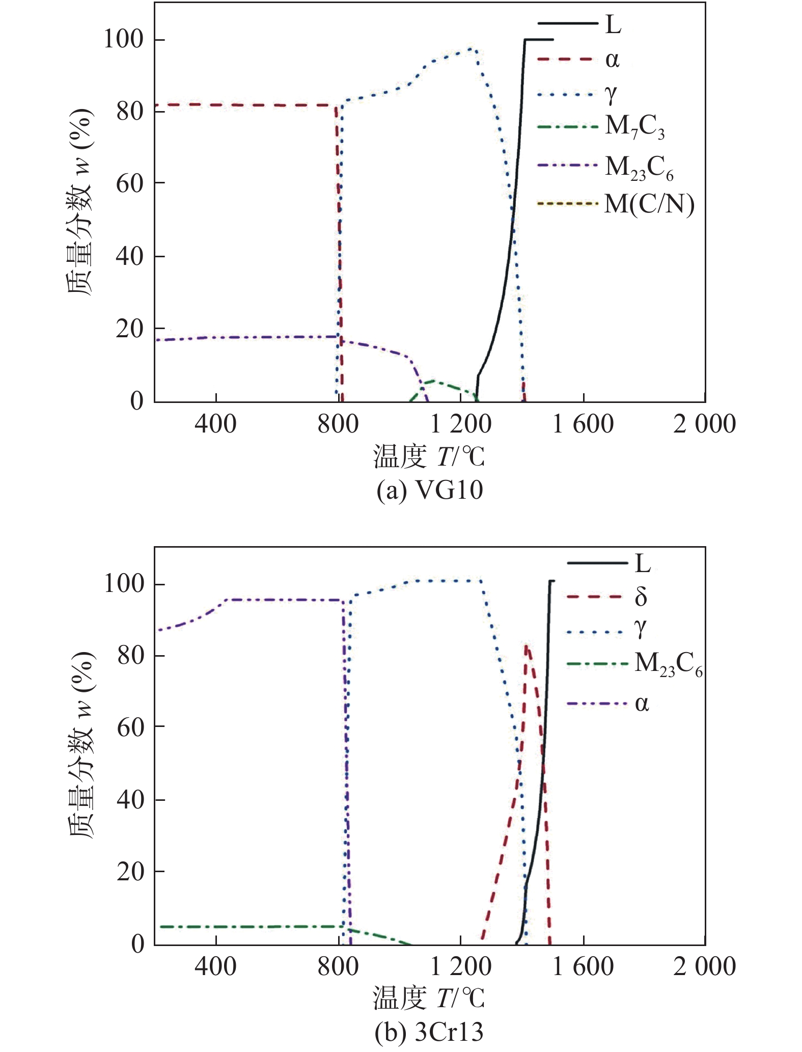
摘要: 采用激光摆动焊接方法焊接异种钢,利用JMATPro软件计算了母材3Cr13,VG10的平衡相图,通过XRD,SEM,EPMA等技术分别对焊缝、熔合区、热影响区的相组成和显微组织进行了分析,测定了焊接接头的显微硬度分布. 试验结果表明,焊缝主要为α相和碳化物M7C3;从熔合线到焊缝中心,组织由平面晶逐渐变为胞状晶、胞状树枝晶、树枝状晶、柱状晶、等轴晶. 焊缝组织存在显微偏析,其中C,Cr元素在晶界富集,Fe元素在晶内富集,同时在晶界处有条棒状的M7C3析出. 熔合线附近的母材处有C迁移现象,其中3Cr13侧母材处有类针状马氏体组织产生,VG10侧熔合区存在非对流混合区,在该位置有块状、岛状组织嵌入母材,且在该组织上有片层状的碳化物生成. 熔合线两侧的母材硬度值最大,焊缝区硬度变化较小,热影响区硬度随着远离焊缝中心距离的增加而逐渐减少.Abstract: After welding dissimilar steel by laser swing welding, the equilibrium phase diagrams of base 3Cr13 and VG10 were calculated by JMATPro software, and the phase composition and microstructure of weld, fusion zone and heat affected zone were analyzed by XRD, SEM, EPMA and other techniques. in addition, the microhardness distribution of welded joints was determined. The results show that the weld is mainly composed of phases and carbides M7C3, and from the fusion line to the weld center, the structure changes from plane crystal to cellular crystal, cellular dendrite, columnar crystal, dendritic crystal and equiaxed crystal. The microstructure of the weld exists micro-segregation, in which C and Cr elements are enriched at the grain boundary, Fe elements are enriched within the grains, and bar-like M7C3 precipitates at the grain boundaries. There is a C migration phenomenon at the base material of the fusion line near. Among them, acicular martensitic structure is generated on the 3Cr13 side, and the unmixed zone exists in the fusion zone on the VG10 side. At this position, the massive, island tissue is embedded in the base Material, and there are lamellar carbides on the structure. The hardness of the base metal on both sides of the fusion line is the largest, and the hardness of the weld zone changes little. The hardness of the heat affected zone decreases with the increase of the distance away from the weld center.
-
Keywords:
- laser welding /
- dissimilar steel /
- microstructure /
- microhardness
-
0. 序言
阳极键合技术以其键合温度低、键合时间短、工艺简单以及硅-玻璃良好键合等特性[1],广泛应用于MEMS器件的气密性封装、垂直互联以及单片集成等方面[2-5].
MEMS器件设计及加工过程中,硅-玻璃的阳极键合技术是体硅工艺中的一项关键技术[6]. 在利用阳极键合制作MEMS器件时常用到两种加工方法:第一种方法中,首先进行体硅工艺,通过反应离子深刻蚀技术制作可动的硅结构,制作玻璃基底,最后通过阳极键合实现二者的结合[6-7]. 第二种方法中,通过硅-玻璃阳极键合,经减薄后结构释放或者采用湿法腐蚀技术进行结构释放[8-12]. 若可动硅结构刚度较小,在第一种方法中容易产生静电黏附,导致器件失效;第二种方法虽然可以通过制作凸块来避免静电黏附,但是制作工艺比较复杂,且键合后再刻蚀会增加玻璃粗糙度,影响光学检测. 同时阳极键合的质量直接决定了MEMS器件的可靠性,键合强度太小,在加工、受到外界冲击时硅-玻璃可能开裂,从而导致器件失效.
文中针对以上问题,采用铬作为选择性阳极键合吸合阻挡层,进行光栅陀螺的制作[2,13],并且进行了键合强度的测试. 首先对陀螺结构与硅吸合进行理论分析,随后进行陀螺硅结构制作,在玻璃基底中采用铝/铬复合金属膜作为光栅层,最后进行键合. 通过键合界面和抗剪强度分析验证在几微米间隙下选择性阳极键合避免静电吸合,键合强度良好.
1. 理论分析
1.1 阳极键合
阳极键合概念最早由Wallis和Pomerantz提出[14],之后在微电子、微机械和光电子等诸多领域应用,该技术现已成为支撑微机电系统的关键技术之一[15]. 当硅-玻璃键合时,硅片放在加热台上加热(其温度低于玻璃的软化点)并接阳极,玻璃接阴极,在阴极阳极之间电场的作用下,Pyrex玻璃的钠离子漂移到负电极,当温度升高到键合温度后在硅-玻璃界面会形成一层空间电荷区也称耗尽层,与此同时在硅片表面上生成镜像电荷,如图1所示. 在正负电荷相互作用下,硅-玻璃界面形成强大的静电吸合力,使得硅片和玻璃紧密接触产生微小形变,在加热加压条件下界面发生阳极氧化反应,生成牢固的化学键O-Si-O[16].
1.2 静电吸合
在阳极键合过程中硅-玻璃之间施加的电压在200~1000 V之间,静电力若大于硅可动结构的机械回复力,则可动结构与玻璃发生吸合,这种现象称为静电吸合. 这里光栅陀螺采用的是离面检测方式,可动结构在离面方向刚度较小,可动结构与玻璃基底间隙只有几微米,这容易在键合时发生硅-玻璃静电吸合,导致器件失效,如图2所示.
![]() 图 2 光栅陀螺不同情况下键合示意图Figure 2. Bonding diagram of grating gyro under different conditions. (a) schematic diagram of ideal bonding; (b) schematic diagram of bonding failure
图 2 光栅陀螺不同情况下键合示意图Figure 2. Bonding diagram of grating gyro under different conditions. (a) schematic diagram of ideal bonding; (b) schematic diagram of bonding failure图3所示,在键合电压作用下,光栅陀螺离面可动结构受到的静电力与其机械回复力大小相等,方向相反.
$${{K}}x{\rm{ = }}\frac{{\varepsilon {\varepsilon _{\rm{0}}}{L_1}{W_1}{U_0}^2}}{{2{{(D - x)}^2}}}$$ (1) 式中:x为可动结构在键合电压作用下的位移;ε为相对介电常数;ε0为真空介电常数;L1为可动结构与玻璃重叠的长度;W1为可动结构与玻璃重叠的宽度;U0为键合电压;D为可动结构与玻璃的初始间隙;K为等效弹性系数.
根据材料力学相关知识,矩形横截面的单端固定梁等效弹性系数为
$${{K = }}\frac{{E{T^3}{W_{\rm{2}}}}}{{{L_{\rm{2}}}^3}}$$ (2) 式中:E为单晶硅弹性模量;T为梁的厚度;W2为梁的宽度;L2为梁的长度.根据静电吸合相关知识,在键合时要避免静电吸合,可动结构的位移x必须小于D/3,因此由式(1)和式(2)可得最大电压为
$${U_0} \leqslant \sqrt {\frac{{{\rm{8}}E{T^3}W_{\rm{2}}^{}{D^3}}}{{27{L_2}^3\varepsilon {\varepsilon _{\rm{0}}}{L_1}{W_1}}}{\rm{ }}}$$ (3) 表1是陀螺梁参数,将现陀螺结构和材料参数带入公式(3)可以得吸合电压约为50 V,这远小于阳极键合电压,即使采用最小的键合电压仍会发生吸合,因此有必要采取措施. 从公式(3)中还可得到可动结构与玻璃的初始间隙D与避免吸合的最大键合电压的关系,建立D与U0的关系如图4所示.
表 1 光栅陀螺结构参数(μm)Table 1. Structure parameters of grating-based gyroscopeT L1 L2 W1 W2 D 80 2 200 2 014 2 200 70 5 ![]() 图 4 吸合电压与间隙关系示意图Figure 4. Schematic of the relationship between pull-in voltage and gap
图 4 吸合电压与间隙关系示意图Figure 4. Schematic of the relationship between pull-in voltage and gap从图4中可以看出随着D的增大,键合电压U0也在增大,D在12 μm之内键合电压U0数值仍远小于阳极键合最小电压,继续增加D可以达到阳极键合电压范围,但D的增加意味着加工硅片方形腔深度的增加. 硅片表面存在较深的腔体会导致匀胶的不均匀,进而会降低光刻质量,使得结构线宽增加[17]. 采用喷胶[18]方法可以使光刻胶均匀,但其致密性不好,在刻蚀机中光刻胶在高温下容易产生气泡,导致刻蚀图形的失真. 所以方形腔不易刻蚀太深,而浅腔容易在键合过程发生吸合,因此考虑到工艺可实施性也有必要采取措施,在保证键合质量下避免在键合中发生吸合现象.
2. 试验与测试
2.1 光栅陀螺工艺设计及加工
光栅陀螺中硅上反射镜与光栅的平行度要求严格,而阳极键合在高的键合电场下可以很好解决这个问题并且键合温度低,结构的残余应力较小.
设计深硅刻蚀与Si-Glass键合技术的工艺流程如图5所示. 硅结构采用400 μm双抛P型硅片,刻蚀面晶相 < 100 >,表面粗糙度约为10 nm;为了保证键合均匀、键合质量良好,基底采用与双抛硅片膨胀系数接近的500 μm厚的BF33玻璃.
![]() 图 5 工艺流程示意图Figure 5. Schematic of processing. (a) sputtering Al/Cr; (b) dry etching of Al/Cr to form grating; (c) DRIE etching cavity and electrode groove; (d) SiO2 was deposited by PECVD and Al was deposited by magnetron sputtering; (e) etching Al electrode; (f) removal of SiO2; (g) DRIE etching beam; (h) DRIE etching back structure; (i) silicon-glass anodic bonding
图 5 工艺流程示意图Figure 5. Schematic of processing. (a) sputtering Al/Cr; (b) dry etching of Al/Cr to form grating; (c) DRIE etching cavity and electrode groove; (d) SiO2 was deposited by PECVD and Al was deposited by magnetron sputtering; (e) etching Al electrode; (f) removal of SiO2; (g) DRIE etching beam; (h) DRIE etching back structure; (i) silicon-glass anodic bonding玻璃工艺制作:通过磁控溅射在玻璃层上沉积采用两种类型光栅层,① Al/Cr光栅层,铬作为键合阻挡层,② Al光栅层(图5a);图形化后采用剥离制成光栅(图5b).
陀螺结构制作:采用感应耦合等离子体(ICP)以6.5 μm/min的蚀刻速率在Si的正面刻蚀一个5 μm深的方形腔体,在腔体内用于陀螺结构制作. 通过感应耦合等离子体(ICP)以同样的蚀刻速率在Si的方形腔外刻蚀0.7 μm深的电极槽(图5c);采用离子体增强化学气相沉积(PECVD)在400 μm厚的Si晶片刻蚀面上沉积SiO2钝化层,通过磁控溅射在SiO2层上沉积Al电极层(图5d);图形化后采用干法刻蚀制成(图5c);为了与玻璃键合,采用湿法腐蚀手段去除金属电极区域以外的钝化层,露出Si表面(图5f). 在5 μm深的方形腔体内采用RIE去除陀螺结构上的SiO2钝化层. 在陀螺结构深硅刻蚀中,额外增加了O2的通入,生成的侧壁阻挡层更加稳定,减少对结构侧壁刻蚀,以3 μm/min的蚀刻速率刻蚀陀螺正面结构,刻蚀深度为80 μm (图5g),刻蚀局部SEM图(图6a),并对梁结构进行测量(图6b),设计值为30 μm,测量值为29.63 μm,光刻版本身有0.2 μm的误差,余下的0.17 μm是由光刻和刻蚀导致的误差. 最后以6.5 μm/min的蚀刻速率进行陀螺结构的背部释放,刻蚀深度为315 μm (图5h).
![]() 图 6 刻蚀结构SEM示意图Figure 6. SEM Schematic of etched structure. (a) schematic diagram of etched local SEM; (b) SEM schematic diagram of beam width
图 6 刻蚀结构SEM示意图Figure 6. SEM Schematic of etched structure. (a) schematic diagram of etched local SEM; (b) SEM schematic diagram of beam width阳极键合:阳极键合一般是在200 ~ 500 ℃,对硅-玻璃施加200 ~ 1000 V电压完成键合. 硅的热膨胀系数随着温度升高而升高,玻璃热膨胀系数基本不会随着温度而变化,键合温度太高硅-玻璃会产生热失配应力,损坏键合晶圆[17]. 在相同键合电压下,温度升高,键合强度增加,在相同键合温度时,增加电压,晶圆结合率也会增加[19],良好的键合质量一般需要在300 ~ 500 ℃才能获得[17]. 综上考虑文中用MA6晶圆对准机将Si-Glass对准后在晶圆键合机中温度为330 ℃,直流电压1000 V条件下进行阳极键合(图5i).
2.2 测试与分析
图7为键合SEM示意图. 键合完成的器件经过划片处理、界面切割后截面未发现吸合现象(图7a),这是由于铬作为阻挡层,玻璃中的氧离子向硅移动时,与铬反应生成的氧化铬为导体[13],氧离子向硅迁移时会从导体中得到电子生成氧气,硅-玻璃之间静电场消失,阻止氧离子向硅中移动,因而无法生成化学键O-Si-O. 若只有铝材料,在键合时,玻璃中的氧离子与铝反应生成铝的氧化物,此时氧离子仍向硅迁移,硅-玻璃之间静电场仍然存在,因而生成化学键O-Si-O,导致吸合现象,器件失效(图7b).
![]() 图 7 有Cr与无Cr情况下键合SEM示意图Figure 7. SEM schematic of bonding. (a) with cr; (b) without Cr
图 7 有Cr与无Cr情况下键合SEM示意图Figure 7. SEM schematic of bonding. (a) with cr; (b) without Cr对键合的表征有以下两个方面(图8):首先通过SEM成像方法进行测试[20]. 键合界面(图8a),通过SEM可以明显看到键合界面没有缺陷,且中间过渡层,宽度约为1 μm,过渡层是硅-玻璃键合的直接原因. 其次采用破坏性试验对键合芯片进行抗剪强度试验. 抗剪强度测试采用Dage4000推拉机进行,此设备由驱动部分、控制系统部分和测量部分、显示部分组成. 将键合样品固定到夹具之间,以推断传感器硅-玻璃得到的最大剪切力进行键合强度表征[1].
![]() 图 8 硅-玻璃键合示意图Figure 8. Schematic of silicon-glass bonding. (a) SEM schematic diagram of silicen-glass bonding interface; (b) schematic diagram of wafer bonding
图 8 硅-玻璃键合示意图Figure 8. Schematic of silicon-glass bonding. (a) SEM schematic diagram of silicen-glass bonding interface; (b) schematic diagram of wafer bonding将晶圆切成样品(图8b)进行测试(图9),器件破坏载荷示意图如图9a所示. 选取的5个器件抗剪强度范围为31~36 MPa (图9b),平均抗剪强度为33.94 MPa,键合质量良好.
![]() 图 9 抗剪强度测试示意图Figure 9. Schematic of shear strength test. (a) schematic diagram of shear test; (b) schematic diagram of shear strength test for five
图 9 抗剪强度测试示意图Figure 9. Schematic of shear strength test. (a) schematic diagram of shear test; (b) schematic diagram of shear strength test for five3. 结 论
(1)推导了长方形梁结构与玻璃静电吸合电压公式并加以计算,从理论上得出吸合电压值远小于键合电压,因此有必要采取措施防止吸合,并建立可动结构与玻璃的初始间隙D与吸合电压U0的关系模型,D在12 μm之内未能达到键合电压条件,而增大D不利于工艺的可实施性,进而也说明了采取措施的必要性.
(2)对Al/Cr,Al光栅玻璃基底进行键合试验,通过界面分析发现,铬阻挡层的存在使得键合成功实现且避免吸合,Al光栅玻璃基底发生吸合.
(3)通过键合强度测试得出光栅陀螺平均抗剪强度33.94 MPa,键合质量良好.
-
![]()
图 1 母材平衡相与温度的关系
Figure 1. Relationship between precipitated phase and temperature of base metal. (a) VG10; (b) 3Cr13
![]()
图 3 焊缝组织形态
Figure 3. Microstructure of the weld. (a) VG10 side; (b) center of weld middle; (c) center of weld top; (d) center of weld bottom; (e) 3Cr13 side
![]()
图 4 焊缝中心组织EDS试验结果
Figure 4. EDS test results of weld center structure. (a) BSE photo of weld center; (b) C element distribution; (c) Cr element distribution; (d) Fe element distribution
![]()
图 5 焊缝两侧熔合区及热影响区
Figure 5. Fusion zone and heat affected zone on both sides of the weld. (a) microstructure of 3Cr13 side; (b) tissue enlarged view of 3Cr13 side; (c) microstructure of VG10 side; (d) tissue enlarged view of VG10 side; (e) carbide morphology at VG10 side
![]()
图 6 焊接接头元素分布
Figure 6. Element distribution of welded joints. (a) photo of weld center; (b) C distribution; (c) Cr distribution; (d) Fe distribution
![]()
图 7 焊接接头显微硬度与位置关系曲线
Figure 7. Relationship between microhardness and position of welded joint
表 1 3Cr13的化学成分(质量分数,%)
Table 1 Chemical composition of 3Cr13
C Si Mn Cr Ni S P Fe 0.29 0.37 0.37 13.8 0.12 0.01 0.02 余量  下载: 导出CSV
表 2 VG10的化学成分(质量分数,%)
Table 2 Chemical composition of VG10
C Si Co Mo Mn V Cr Ni S P Fe 0.98 0.41 1.1 0.98 0.41 0.28 14.92 0.32 < 0.01 0.02 余量
下载: 导出CSV
表 3 激光焊接工艺参数
Table 3 Parameters of laser welding
激光功率P/W 焊接速度v/(mm·s−1) 离焦量△f/mm 保护气流量Q/(L·min−1) 摆动频率f/Hz 摆动幅度A/mm 3 750 43 + 2 20 200 0.3
下载: 导出CSV
-
[1] Mittal R, Sidhu B S. Microstructures and mechanical properties of dissimilar T91/347H steel weldments[J]. Journal of Materials Processing Technology, 2015, 220: 76 − 86. doi: 10.1016/j.jmatprotec.2015.01.008
[2] 王瑞, 石玗, 李广, 等. 镍对铜/不锈钢GTAW接头导电性及腐蚀性能的影响[J]. 焊接学报, 2019, 40(12): 53 − 58. Wang Rui, Shi Yu, Li Guang, et al. Effect of nickel on conductivity and corrosion of copper/stainless steel GTAW joints[J]. Transactions of the China Welding Institution, 2019, 40(12): 53 − 58.
[3] Liu Liming, Zhou Yanbin. Mechanism analysis of free formation of backing weld by the pulsed MAG-TIG double arc tandem welding[J]. China Welding, 2019, 28(4): 8 − 15.
[4] Liu G L, Yang S W, Han W T, et al. Microstructural evolution of dissimilar welded joints between reduced-activation ferritic-martensitic steel and 316L stainless steel during the post weld heat treatment[J]. Materials Science and Engineering: A, 2018, 722: 182 − 196. doi: 10.1016/j.msea.2018.03.035
[5] 刘桐, 杨立军, 邱文聪, 等. 304不锈钢激光深熔焊元素蒸发及焊缝合金含量变化[J]. 焊接学报, 2018, 39(2): 8 − 12. Liu Tong, Yang Lijun, Qiu Wencong, et al. Vaporization and composition change of 304 stainless steel during keyhole mode laser welding[J]. Transactions of the China Welding Institution, 2018, 39(2): 8 − 12.
[6] 母晓红, 牛旭, 惠文. 激光焊的原理及其应用研究[J]. 科技创新导报, 2009(8): 5 − 6. doi: 10.3969/j.issn.1674-098X.2009.08.004 Mu Xiaohong, Niu Xu, Hui Wen. Principle and application of laser welding[J]. Science and Technology Innovation Herald, 2009(8): 5 − 6. doi: 10.3969/j.issn.1674-098X.2009.08.004
[7] He Yannan, Song Qiang, Sun Kang, et al. Microstructure and properties of in-situ chromium carbide composite coating by laser cladding[J]. China Welding, 2018, 27(4): 10 − 17.
[8] 宗攀, 张覃轶, 孙伟, 等. 热处理工艺对大马士革VG10钢组织和性能的影响[J]. 金属热处理, 2018(11): 117 − 122. Zong Pan, Zhang Qinyi, Sun Wei, et al. Effect of heat treatment process on microstructure and mechanical properties of Damascus VG10 steel[J]. Heat treatment of metals, 2018(11): 117 − 122.
[9] 尹燕, 栗子林, 许广伟, 等. 3Cr13厨刀碟片激光同轴送粉熔覆层的显微硬度与组织[J]. 焊接学报, 2016, 37(10): 86 − 87. Yin Yan, Li Zilin, Xu Guangwei, et al. Microhardness and microstructure of laser cladding layer on 3Cr13 kitchen knife by disc laser coaxial powder[J]. Transactions of the China Welding Institution, 2016, 37(10): 86 − 87.
[10] 徐仰涛, 沙岐振. 基于JMatPro软件对不同B含量下Co-8.8Al-9.8W合金析出相的热力学模拟计算[J]. 稀有金属材料与工程, 2016, 45(9): 2332 − 2336. Xu Yangtao, Sha Qizhen. Thermodynamic simulation calculation of Co-8.8A1-9.8W alloy with different B contents based on JMatPro software[J]. Rare Metal Materials and Engineering, 2016, 45(9): 2332 − 2336.
[11] 王鲁, 杨钢, 刘正东, 等. 基于Thermo-Calc和JMatPro模拟计算的新型镍基合金设计[J]. 材料热处理学报, 2017, 38(4): 193 − 199. Wang Lu, Yang Gang, Liu Zhengdong, et al. Design of a new Ni-base alloy based on simulated calculation on Thermo-Calc & JMatPro[J]. Transaction of Materials and Heat Treatment, 2017, 38(4): 193 − 199.
[12] 黄继华. 焊接冶金原理[M]. 北京: 机械工业出版社, 2015. Huang Jihua. Principle of welding metalluryy[M]. Beijing: China Machine Press, 2015.
[13] 魏翔云, 张玉生. 碳含量对Fe-30Ni-20Cr-6Mo铸造合金元素偏析和耐蚀性的影响[J]. 腐蚀科学与防护技术, 1996(3): 210 − 213. Wei Xiangyun, Zhang Yusheng. Effect of carbon content on element segregation and corrosion-resistance of cast alloy fe-30Ni-20Cr-6Mo[J]. Corrosion Science and Protection Technology, 1996(3): 210 − 213.
[14] 潘春旭. 异种钢及异种金属焊接显微结构特征及其转变机理[M]. 北京: 人民交通出版社, 2000. Pan Chunxu. Microstructure characteristics and transformation mechonism of dissimilar sreels and metals[M]. Beijing: China Communications Press, 2000.
[15] Wieczerzak K, Bala P, Stepien M, et al. Formation of eutectic carbides in Fe-Cr-Mo-C alloy during non-equilibrium crystallization[J]. Materials & Design, 2016, 94(3): 61 − 68.
[16] Chang C M, Lin C M, Hsieh C C, et al. Effect of carbon content on microstructural characteristics of the hypereutectic Fe-Cr-C claddings[J]. Materials Chemistry and Physics, 2009, 117(1): 257 − 261. doi: 10.1016/j.matchemphys.2009.05.052
-
期刊类型引用(0)
其他类型引用(4)


计量
- 文章访问数: 468
- HTML全文浏览量: 59
- PDF下载量: 48
- 被引次数: 4
