
Influence of process parameters on microstructure and mechanical properties in high power ultrasonic welding of Cu/Al
-
摘要: 尽管大功率超声波焊接可以更好的焊接较高的导电、导热性的材料,但是对焊接机理的认识还很少. 为了深入明晰焊接过程以及得到高质量的Cu/Al焊接接头,研究了不同夹紧力、焊接时间、焊接振幅以及焊头形状对Cu/Al大功率超声波焊接的界面温度、中间相生长和接头力学性能的影响. 结果表明,随着夹紧力的增大,界面中间相厚度先增大后减小. 随着焊接振幅的下降,界面温度的降幅增大且中间相厚度呈现近似线性下降. 最优的焊头齿数为9个,焊头齿数的增多和减少均会导致界面温度降低和焊接裂纹产生. 为获得较高的Cu/Al大功率超声波焊接质量,焊接振幅应设置为最高. 对焊接接头的拉伸断口进行扫描电镜测试表明,Cu/Al超声波焊接接头的断裂模式是韧性-脆性复合断裂. 研究结果为优化超声波焊接工艺参数提供了指导.Abstract: Although high power ultrasonic spot welding(USW) can obtain better welding quality about highly conductive materials, the welding mechanism is still unclear. To improve the understanding of the USW process and to enhance the weld strength in similar Cu/Al welding, the effect of clampling force, welding time, vibration amplitude and profile of the sonotrode tips on the temperature rise, intermetallic compound (IMC) growth of welding interface and mechanical properties of joint during Cu/Al high power ultrasonic welding process are investigared. Increasing of clampling force, the thickness of the IMC first increases and then decreases. The interface temperature decreases and the thickness of the IMC decreases linearly with vibration amplitude. The optimal number of welding head teeth is 9. Increasing and decreasing the number of sonotrode teeth will lead to lower interface temperature and formation of welding cracks. In order to obtain high welding quality of Cu/Al joint, the vibration amplitude sholud be set to its maximum. Scanning electron microscopy (SEM) test is performed on the fracture of the Cu/Al joint and shows that the fracture of Cu/Al ultrasonic welded joint is ductile-brittle hybrid mode. The research results provide guidance for optimizing the ultrasonic welding parameters.
-
Keywords:
- ultrasonic welding /
- dissimilar metals /
- intermetallic compound /
- mechanical property
-
0. 序言
随着电子元器件封装密度的增加,陶瓷球栅阵列(CBGA)和陶瓷柱栅阵列(CCGA)因其高密度的面排布引脚形式,在航空航天等高可靠性领域产品中得到了广泛应用[1-2]. CBGA和CCGA封装器件分别通过陶瓷管壳上的焊球和焊柱实现与PCB基板的组装互连,由于氧化铝陶瓷管壳(热膨胀系数为6.5 × 10⁻⁶/℃)和PCB基板(热膨胀系数为18 × 10−6 ~ 21 × 10−6/℃)的热膨胀系数差了近3倍,这种差异会在温度变化过程中产生剪切应变而导致裂纹萌生,进而引发焊点失效,因此温度循环成为了封装器件可靠性评估的关键手段. CCGA封装是在CBGA封装的基础上,用柱栅阵列代替了球栅阵列,增加互连引脚的距离,大大缓解了热膨胀系数不匹配带来的焊点失效问题,提高了焊点的可靠性,成为大尺寸产品封装的更优选择[3-5].
在温度循环过程中,焊点的界面显微组织会发生变化,包括金属间化合物(IMC)的成分及厚度等[6-8],界面的显微组织会影响焊点的可靠性,焊点的抗剪强度是反映其可靠性最直观的方式,因此分析温度循环过程中焊点的显微组织与抗剪强度的演变关系对揭示CCGA封装焊点的失效机理及建立可靠性评估依据具有重要的参考价值.
文中以CCGA484封装器件为研究对象,分析温度循环过程中焊点的界面显微组织演变与抗剪强度的对应关系,研究温度循环过程中焊点的失效机理,为CCGA封装的发展及应用提供理论指导.
1. 试验方法
1.1 原材料及试验样品制备
试验中选用高温共烧氧化铝陶瓷外壳,型号为CLGA484,镀层为Ni/Au,焊盘直径为ϕ0.8 mm ± 0.05 mm,焊盘间距为1.27 mm,板级封装用PCB板上的焊盘直径为ϕ0.8 mm ± 0.05 mm,焊柱采用ϕ0.51 mm × 2.21 mm的Pb90Sn10普通高铅焊柱,植柱和组装到PCB板上采用的锡膏均采用Sn63Pb37.
试验样品制备过程为:丝网印刷锡膏→植柱→真空回流焊接→清洗→PCB板喷印锡膏→CCGA器件与PCB焊盘喷印锡膏光学对位→真空回流焊接,完成板级封装后的试验样品如图1所示,将组装到PCB板的试样与未组装的CCGA器件同时进行温度循环试验,前者用于观察不同温度循环次数下焊柱的外观形貌,后者用于焊点的金相分析和剪切力测试.
1.2 温度循环条件
对CCGA484试验样品进行温度循环试验,试验条件按照美军标MIL-STD-883. 温度循环曲线如图2所示,温度范围为−65 ~ 150 ℃,循环周期为50 min,高低温保温时间均为15 min,升降温速率相同,试验过程中,每隔100次温度循环取出进行形貌观察、剪切力测试和金相分析,共进行500次温度循环.
1.3 抗剪强度测试
选用抗剪强度作为CCGA焊点的可靠性评估依据,试验设备采用专门的微焊点强度测试仪(DAGE4800),剪切速度均为0.4 mm/s,由于CCGA484器件的焊柱间距较小,试验过程中需要铲去周围的焊柱,保证剪切工具在行进时不会接触其它材料.
2. 试验结果与分析
2.1 焊柱宏观形貌演变分析
由于陶瓷管壳和PCB板的热膨胀系数差别较大,这种热失配会在温度变化过程中产生剪切应变,宏观表现为焊柱发生塑性变形.
温度循环过程中焊柱形貌如图3所示. 从图中可以看出,温度循环次数达到400次时,焊柱在反复热冲击作用下开始发生明显的塑性变形,且表面变得更加粗糙,焊点位置伴随有轻微的颈缩现象,500次后焊柱的扭曲程度进一步加剧,但肉眼还未观察到焊点开裂现象.
![]() 图 3 不同温度循环次数下CCGA封装器件的宏观形貌Figure 3. Evolution of solder column morphology at different thermal cycling times. (a) 100 times; (b) 300 times; (c) 400 times; (d) 500 times
图 3 不同温度循环次数下CCGA封装器件的宏观形貌Figure 3. Evolution of solder column morphology at different thermal cycling times. (a) 100 times; (b) 300 times; (c) 400 times; (d) 500 times由于焊柱在长时间的高温、恒压力作用下,即使应力小于屈服强度也会慢慢发生蠕变变形[9]. 在温度循环的升温及高温保温阶段,陶瓷的热膨胀系数大于PCB基板,焊柱发生倾斜,在温度循环的降温及低温保温阶段,焊柱恢复至初始状态后向相反方向偏移,在反复的升温降温过程中,焊柱蠕变变形逐渐累积,达到宏观可见的扭曲状态,而焊点钎料的强度要略大于焊柱,因此在焊点处会有颈缩现象产生.
2.2 焊点显微组织分析
在焊点形成过程中,钎料与焊盘金属在短时间的高温作用下扩散生成硬脆的IMC层,实现焊柱与基板之间的电气和机械连接,但是在长时间的温度循环过程中,扩散作用导致IMC层厚度逐渐增加,其成分也会发生相应的变化,由于IMC的热膨胀系数与钎料相差较大,因此过厚的IMC会对焊点的可靠性产生不利的影响.
不同温度循环次数下的CCGA焊点界面显微组织如图4所示,在温度循环前,高铅焊柱与Ni焊盘界面观察不到明显的IMC层,因为Ni相对稳定,其界面反应层与铜相比是相当薄的,所以观察不到,随着循环次数增加,界面出现不同颜色对比度的中间层,且厚度逐渐增加,根据Ni-Sn二元相图可知,Sn-Pb钎料与Ni焊盘扩散反应生成的界面IMC从Ni侧依次包括Ni3Sn,Ni3Sn2和Ni3Sn4,具体的化合物成分取决于Sn与Ni的相对浓度.
![]() 图 4 CCGA封装器件焊点显微组织Figure 4. Microstructure of CCGA solder joints at different thermal cycling times. (a) original; (b) 100 times; (c) 200 times; (d) 300 times
图 4 CCGA封装器件焊点显微组织Figure 4. Microstructure of CCGA solder joints at different thermal cycling times. (a) original; (b) 100 times; (c) 200 times; (d) 300 times采用EDS分析界面IMC成分,不同温度循环次数下测试IMC成分的位置如图5 ~ 图7所示,对应不同位置的成分如表1所示. 从图中可以看出,100次温度循环时,界面点1主要为偏析的富锡相,点2处Ni与Sn的原子比接近3∶4,结合Ni-Sn二元相图可知,应为Ni3Sn4化合物,与已有的研究一致[8];在200次温度循环后,界面点1处仍为Ni3Sn4相,靠近Ni焊盘侧的点2处Ni与Sn的原子比接近3∶2,推测为Ni3Sn2相;500次温度循环后,在Ni与Ni3Sn2相之间的点2处,Ni与Sn的原子比接近3∶1,应为Ni3Sn相,因此推测随着温度循环次数增加,从焊柱到Ni焊盘之间依次生成的IMC为富锡相→Ni3Sn4→Ni3Sn2→Ni3Sn. 分析IMC形成过程,认为在温度循环前,富锡相与Ni通过元素相互扩散,反应生成极少量Ni3Sn4化合物层,Ni3Sn4化合物层的生成阻挡了Sn与Ni的扩散反应,Ni与Ni3Sn4化合物层中微量的Sn继续发生扩散反应,生成Ni含量更高的Ni3Sn2化合物相,之后,Ni3Sn2化合物层进一步阻挡Ni3Sn4化合物层中Sn与Ni的扩散反应,生成Ni含量更高的Ni3Sn化合物相. 统计不同温度循环次数下界面IMC厚度,如图8所示,两者基本呈指数为1/2的幂函数增长关系,符合扩散控制机制.
![]() 图 5 温度循环100次焊点界面IMC成分Figure 5. IMC component of CCGA solder joints at thermal cycling of 100 times
图 5 温度循环100次焊点界面IMC成分Figure 5. IMC component of CCGA solder joints at thermal cycling of 100 times![]() 图 7 温度循环500次焊点界面IMC成分Figure 7. IMC component of CCGA solder joints at thermal cycling of 500 times
图 7 温度循环500次焊点界面IMC成分Figure 7. IMC component of CCGA solder joints at thermal cycling of 500 times![]() 图 6 温度循环200次焊点界面IMC成分Figure 6. IMC component of CCGA solder joints at thermal cycling of 200 times
图 6 温度循环200次焊点界面IMC成分Figure 6. IMC component of CCGA solder joints at thermal cycling of 200 times界面IMC层存在离子键或共价键,所以往往具有硬脆特性,与基板和焊柱的线膨胀系数差别较大,随着温度循环次数增加,硬脆的IMC层厚度会逐渐增加,因此焊点界面处会产生较大的应力集中,在反复热应力作用下会萌生不同方向的细微裂纹,如图7所示,推测随着温度循环次数继续增加,应力集中导致微裂纹沿着剪切应变方向逐渐扩展,直到覆盖整个焊点,导致基板与焊柱之间发生断裂失效.
表 1 不同温度循环次数下焊点界面的成分分析Table 1. Component of CCGA solder joints at different thermal cycling times循环次数 界面点 质量分数w(%) 原子分数a(%) Pb Sn Ni Pb Sn Ni 100 点1 13.43 76.39 10.18 7.35 72.99 19.66 点2 4.97 69.37 25.66 2.3 55.9 41.8 200 点1 9 64.83 26.17 4.2 52.75 43.05 点2 4.91 51.99 43.1 1.93 35.63 62.44 500 点1 8.77 45.44 45.79 3.51 31.77 64.72 点2 8.24 28.16 63.6 2.92 17.44 79.64 ![]() 图 8 温度循环次数与界面IMC厚度的关系Figure 8. Variations of IMC thickness of CCGA solder joint with different thermal cycling times
图 8 温度循环次数与界面IMC厚度的关系Figure 8. Variations of IMC thickness of CCGA solder joint with different thermal cycling times2.3 抗剪强度测试结果与分析
焊点的力学性能是评估其可靠性的最直观方法之一,采用DAGE4800微焊点强度测试仪测试不同循环次数下焊点的抗剪强度,如图9所示. 随着温度循环次数的增加,CCGA封装焊点的抗剪强度呈现下降趋势,到500次温度循环结束,抗剪强度相对下降了15.6%,且下降的速率逐渐增大. 结合上文界面显微组织分析可知,长时间高温会促进界面元素相互扩散,依次生成Ni3Sn4,Ni3Sn2和Ni3Sn多种IMC化合物层,且IMC层厚度逐渐增加,这些化合物与Sn,Pb的晶格常数和晶格结构存在较大差异,具有较高的熔点,呈现硬脆特性,因此在反复塑性变形过程中会产生应力集中,容易萌生裂纹而导致焊点失效,所以焊点的力学性能随着IMC厚度增加而逐渐下降,与已有的研究结果一致[10]. 对抗剪强度Rτ与温度循环次数n之间的关系做曲线拟合,得到下式,即
![]() 图 9 不同循环次数下焊点剪切力变化Figure 9. Variations of shear strength of CCGA solder joints with different thermal cycling times
图 9 不同循环次数下焊点剪切力变化Figure 9. Variations of shear strength of CCGA solder joints with different thermal cycling times$${R_\tau } = 682.25 - 0.06\;n - 2.77 \times {10^{ - 4}}{n^2}$$ (1) 根据技术指标要求,焊柱的最小剪切力为5.6 N,由式(1)推算可得,当温度循环次数大于550次时,焊点的抗剪强度将不满足要求.
3. 结论
(1) 温度循环超过400次时,CCGA器件焊柱开始发生明显的塑性变形.
(2) CCGA封装器件的焊点随着温度循环次数增加,从Ni焊盘侧依次生成的IMC层成分为Ni3Sn→Ni3Sn2→Ni3Sn4,且IMC层厚度逐渐增加.
(3) CCGA封装器件焊点的抗剪强度随着温度循环次数增加呈下降趋势,且下降的速率逐渐增大,到500次温度循环结束,抗剪强度相对下降了15.6%,这是由于硬脆的IMC层厚度增加,在变形过程中导致应力集中而引发焊点失效.
-
![]()
图 2 不同齿间距下的焊头形状和主要尺寸(mm)
Figure 2. Profile and dominant dimensions of the sonotrode tips with different tooth intervals. (a) 0.8 mm; (b) 0.9 mm; (c) 1.0 mm
![]()
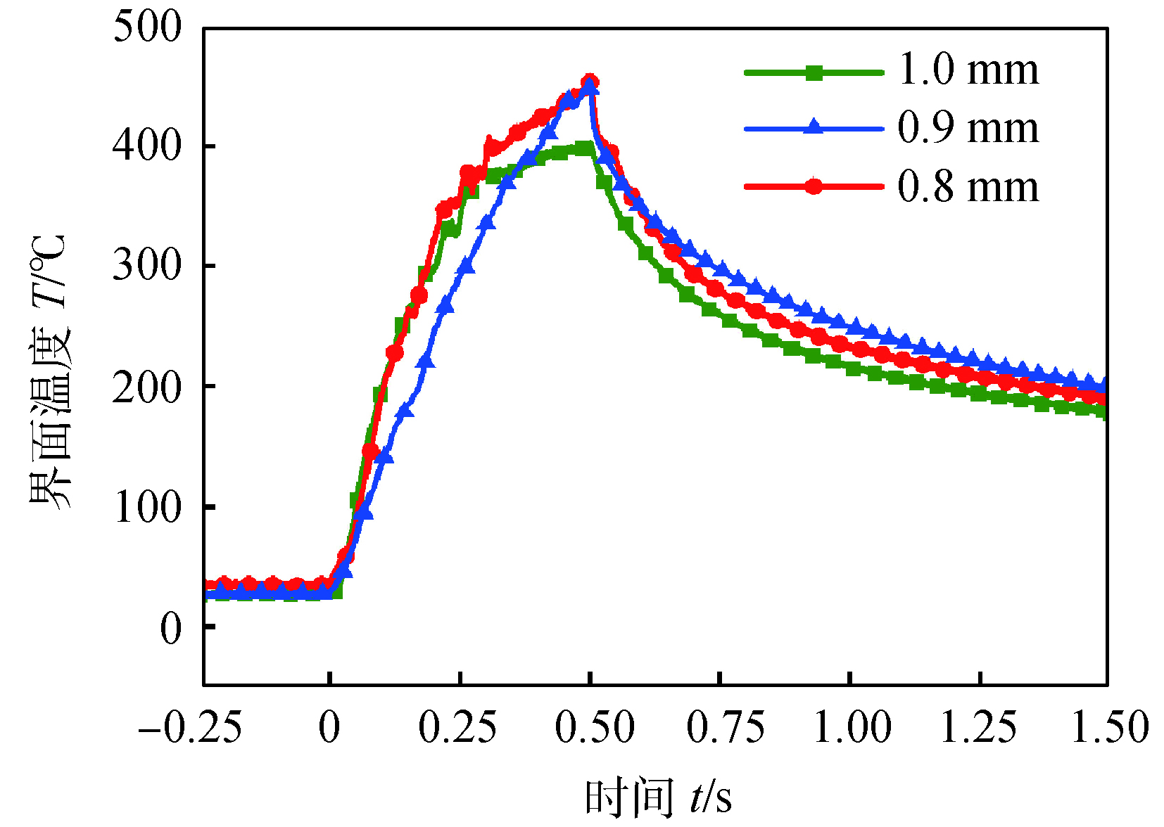
图 3 不同夹紧力下界面温度测量结果
Figure 3. Interface temperature results under different clampling force
![]()
图 4 不同焊接振幅下界面温度测量结果
Figure 4. Interface temperature results under different vibration amplitude
![]()
图 5 不同焊接时间下界面中间相形貌
Figure 5. Morphology of IMC at different welding time. (a) 0.2 s; (b) 0.3 s; (c) 0.4 s; (d) 0.5 s
![]()
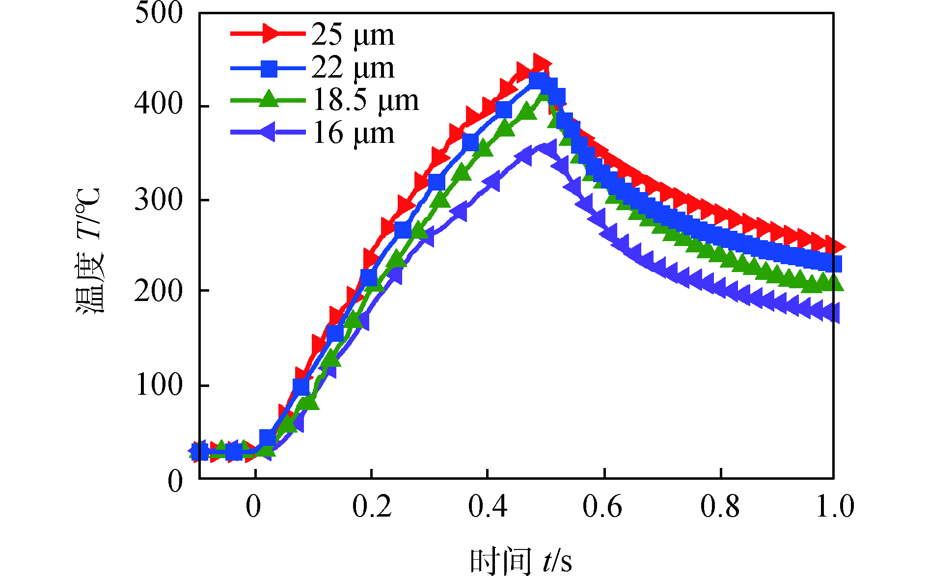
图 7 不同焊接振幅下Cu/Al中间相形貌
Figure 7. Morphology of Cu/Al interphase under different vibration amplitude. (a) 25 μm; (b) 22 μm; (c) 18.5 μm; (d) 16 μm
![]()
图 9 不同焊头齿间距下界面温度
Figure 9. Interface temperature under different sonotrode tooth intervals
![]()
图 10 不同焊头齿间距下的焊接横截面形貌
Figure 10. Profile of weld cross-section at different sonotrode tooth intervals. (a) 0.8 mm; (b) 1.0 mm
![]()
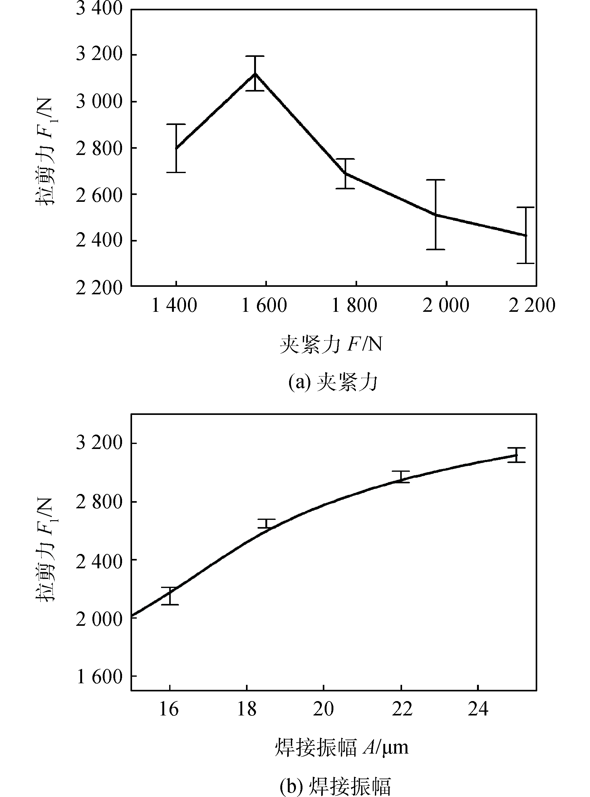
图 11 接头拉剪力随焊接压力和焊接振幅的变化
Figure 11. Lap-shear force under different clamplingpressures and vibration amplitudes. (a) clampling pressures; (b) vibration amplitudes
-
[1] Bakavos D, Prangnell P B. Mechanisms of joint and microstructure formation in high power ultrasonic spot welding 6111 aluminium automotive sheet[J]. Materials Science and Engineering A, 2010, 527(23): 6320 − 6334. doi: 10.1016/j.msea.2010.06.038
[2] Zhang Changqing, Lü Guangming, Jin Xin, et al. Study of joining mechanism of ABS polymer and steel/aluminum by resistance spot welding[J]. China Welding, 2018, 27(2): 57 − 61.
[3] Li Huan, Cao Biao, Liu Jian, et al. Modeling of high-power ultrasonic welding of Cu/Al joint[J]. The International Journal of Advanced Manufacturing Technology, 2018, 97(1−4): 833 − 844. doi: 10.1007/s00170-018-2002-1
[4] Ni Z L, Yang J J, Gao Z T, et al. Joint formation in ultrasonic spot welding of aluminum to copper and the effect of particle interlayer[J]. Journal of Manufacturing Processes, 2020, 50(2): 57 − 67.
[5] Zhang Z, Wang K, Li J, et al. Investigation of interfacial layer for ultrasonic spot welded aluminum to copper joints[J]. Scientific Reports, 2017, 7(1): 12505. doi: 10.1038/s41598-017-12164-2
[6] Wang G Q, Zhao Y H, Zhang L N, et al. A new weld repair technique for friction stir welded aluminium structure: inertia friction pull plug welding[J]. China Welding, 2017, 26(4): 56 − 64.
[7] Shakil M, Tariq N H, Ahmad M, et al. Effect of ultrasonic welding parameters on microstructure and mechanical properties of dissimilar joints[J]. Materials & Design, 2014, 55(3): 263 − 273.
[8] Nong L, Shao C, Kim T H, et al. Improving process robustness in ultrasonic metal welding of lithium-ion batteries[J]. Journal of Manufacturing Systems, 2018, 48(7): 45 − 54.
[9] 李东, 赵杨洋, 张延松. 焊接能量对铝/铜超声波焊接接头显微组织的影响[J]. 焊接学报, 2014, 35(2): 47 − 50. Li Dong, Zhao Yangyang, Zhang Yansong. Effect of welding energy on microstructures of the Al/Cu joints obtained by ultrasonic welding[J]. Transactions of the China Welding Institution, 2014, 35(2): 47 − 50.
[10] 解龑, 冯梦楠, 罗震. 齿形对超声波焊接泡沫镍薄板与实体铝薄板的影响[J]. 焊接学报, 2018, 39(12): 5 − 8. doi: 10.12073/j.hjxb.2018390288 Xie Yan, Feng Mengnan, Luo Zhen. Effect of teeth shape on ultrasonic spot welding joints of nickel foam sheet and aluminum solid sheet[J]. Transactions of the China Welding Institution, 2018, 39(12): 5 − 8. doi: 10.12073/j.hjxb.2018390288
[11] Feng M N, Xie Y, Zhao C F, et al. Microstructure and mechanical performance of ultrasonic spot welded open-cell Cu foam/Al joint[J]. Journal of Manufacturing Processes, 2018, 33(6): 86 − 95.
[12] Li Huan, Cao Biao, Yang Jingwei, et al. Modeling of resistance heat assisted ultrasonic welding of Cu-Al joint[J]. Journal of Materials Processing Technology, 2018, 256(6): 121 − 130.
[13] Satpathy M P, Sahoo S K. Mechanical performance and metallurgical characterization of ultrasonically welded dissimilar joints[J]. Journal of Manufacturing Processes, 2017, 25(1): 443 − 451.
[14] Bergmann J P, Regensburg A, Schürer R, et al. Effect of the interface characteristics on the joint properties and diffusion mechanisms during ultrasonic metal welding of Al/Cu[J]. Welding in the World, 2017, 61(3): 499 − 506. doi: 10.1007/s40194-017-0449-6
[15] Satpathy M P, Mohapatra K D, Sahoo S K. Ultrasonic spot welding of Al-Cu dissimilar metals: a study on parametric influence and thermo-mechanical simulation[J]. International Journal of Modelling and Simulation, 2018, 38(2): 83 − 95. doi: 10.1080/02286203.2017.1395198
[16] Yang J, Cao B, Lu Q. The effect of welding energy on the microstructural and mechanical properties of ultrasonic-welded copper joints[J]. Materials, 2017, 10(2): 1 − 13.
-
期刊类型引用(10)
1. 陈澄,尹红波,王成,倪大海,谢璐,曾超林. 钼铜载体与铝合金外壳的无压纳米银胶低温烧结强度. 半导体技术. 2025(01): 95-100 .  百度学术
百度学术
2. 黄玺,张亮,王曦,陈晨,卢晓. 电子封装用纳米级无铅钎料的研究进展. 材料导报. 2024(23): 136-148 . 百度学术
3. 黄天,甘贵生,刘聪,马鹏,江兆琪,许乾柱,陈仕琦,程大勇,吴懿平. 电子封装低温互连技术研究进展. 中国有色金属学报. 2023(04): 1144-1178 . 百度学术
4. 官紫妍,吴丰顺,周龙早,李可为,丁立国,李学敏. 功率模块纳米银烧结技术研究进展. 电子工艺技术. 2023(04): 1-6 . 百度学术
5. 傅必成,方毅,张乐,李道会,齐放,宋利军,祝温泊. Fluxless bonding with silver nanowires aerogel in die-attached interconnection. China Welding. 2023(02): 32-41 . 百度学术
6. 杜伟,强军锋,余竹焕,高炜,阎亚雯,王晓慧,刘旭亮. 电子封装用纳米复合焊膏的研究进展. 材料导报. 2023(19): 162-172 . 百度学术
7. 龙旭,种凯楠,苏昱太. 烧结银细观孔隙结构对宏观力学性能的影响. 焊接学报. 2023(12): 15-20+27+137-138 . 本站查看
8. 齐苗苗,贺晓斌,刘双宝,杨婉春,祝温泊. Ag-Cu固溶体颗粒制备及低温烧结互连接头性能. 焊接学报. 2022(07): 97-101+119 . 本站查看
9. 杨婉春,胡少伟,祝温泊,李明雨. 低温烧结纳米银膏研究进展. 焊接学报. 2022(11): 137-146+169-170 . 本站查看
10. 王刘珏,瞿昀昊,吉勇. 颗粒形貌对银焊膏无压烧结行为的影响. 材料导报. 2022(S2): 347-351 . 百度学术
其他类型引用(10)

 下载:
下载:


计量
- 文章访问数: 644
- HTML全文浏览量: 53
- PDF下载量: 80
- 被引次数: 20
