
Welding deviation measurement method based on welding torch contour feature extraction
-
摘要: 在熔化极气体保护焊(gas metal welding, GMAW)焊接过程中,由于弧光干扰严重,视觉系统难以同时准确提取焊缝和焊丝尖端,从而影响焊缝跟踪的精度.针对这个问题,提出一种定位焊枪中心来替代定位焊丝尖端的焊接偏差测定方法,并对该方法进行了可行性论证.首先,在增强熔池图像中的焊缝、焊枪边缘轮廓信息后,设置矩形窗获得边缘采样点.然后,使用聚类算法筛选出正确的边缘采样点,根据采样点利用最小二乘法拟合出焊缝直线和焊枪椭圆方程.最后,计算当前图像焊枪中心与焊缝直线的距离,与基准图像中的对应距离进行比较,测定出焊枪位置偏差量和焊枪摆幅偏差量.实际验证结果表明,焊枪中心与焊丝尖端的替代误差在0.2 mm以内,满足跟踪精度要求,具有较强的工程实际意义.Abstract: In the welding process of gas metal welding (GMAW), due to the serious arc interference, it is difficult for the vision system to accurately extract the weld and the wire tip at the same time, thus affecting the accuracy of the weld tracking. An approach was proposed to locate the welding torch center instead of the welding wire tip. The feasibility of the method was demonstrated. First, after enhancing the weld seam and weld gun edge contour information in the molten pool image, a rectangular window was set to obtain the edge sampling point. Then, the clustering algorithm was used to screen out the correct edge sampling points. The weld line and the ellipse equation of the torch were fitted by the least squares method according to the sampling points. Moreover, the distance between the center of the current image welding torch and the straight line of the weld was calculated. Compared with the corresponding distance in the reference image, the amount of deviation of the welding torch position and the deviation of the welding gun swing were detected. The actual verification results show that the replacement error between the center of the welding torch and the tip of the welding wire is within 0.2 mm, which meets the requirements of tracking accuracy and has strong engineering practical significance.
-
0. 序言
近年来,随着机器人和机器视觉技术的进步,智能化焊接得到了快速的发展与广泛应用.在石油化工现场施工中,管道自动焊接一直是研究的热点.管道自动焊接的核心问题在于如何实现管道焊缝的精准跟踪引导,进而实时控制爬行焊接机器人的焊枪运行轨迹,以满足焊接质量的要求.
早期研究焊缝跟踪的方法主要基于探针接触式传感、电磁传感、超声波传感、电弧传感和红外传感等[1-3]. 近年来由于视觉传感具有应用范围广、无接触、跟踪精度高等优势,焊缝视觉跟踪已成为智能化焊接行业研究的热点.焊缝视觉跟踪技术一般可分为主动视觉传感和被动视觉传感两大类[4].主动视觉传感主要采用相机结合光源或相机结合结构光的方法[5-6],该方法采用超前监测的方式,即视觉监测位置与焊接位置存在着一定的前视距离.超前监测的优势在于采集焊缝的图像能够有效的避免焊接过程中电弧光和焊渣飞溅的干扰,焊缝图像的质量得到明显提高,缺点是无法实时观测到熔池形貌变化和焊丝的位置,且给焊缝视觉跟踪系统引入了超前误差,导致焊缝视觉跟踪精度不够理想.被动视觉传感是利用焊接过程中熔池的高亮状态或是对电弧光的反射来获得焊缝图像[7-8],该方法具有实时监测熔池和观测焊丝位置的优势,并且不存在超前监测误差,但焊接过程中电弧光和焊渣飞溅非常强烈,以至于被动视觉传感方式获取的图像受干扰严重,准确定位焊丝尖端位置困难.
实时焊缝跟踪技术的关键点在于能够同时获取焊缝和焊丝尖端的位置信息,根据焊缝和焊丝尖端的相对位置即可测定出偏差量.普通CCD摄像机抗弧光能力较弱,无法同时获取两者的清晰图像,而专业焊接摄像机价格昂贵,导致自动焊接设备成本增加,不利于自动焊接设备的推广应用.经研究分析大量的由普通CCD摄像机采集的熔池图像后发现,焊缝特征明显的同时焊枪轮廓也较为清晰,且焊丝的位置和运动轨迹与焊枪具有一致性,因此,提出了一种定位焊枪中心来替代定位焊丝尖端的焊接偏差测定方法,并对该方法做了大量的试验进行可行性分析.该方法的实现有利于实时快速测定焊接偏差量,降低设备成本,对实现智能化焊接具有实际意义.
1. 焊接偏差测定系统
1.1 试验系统与运行机制
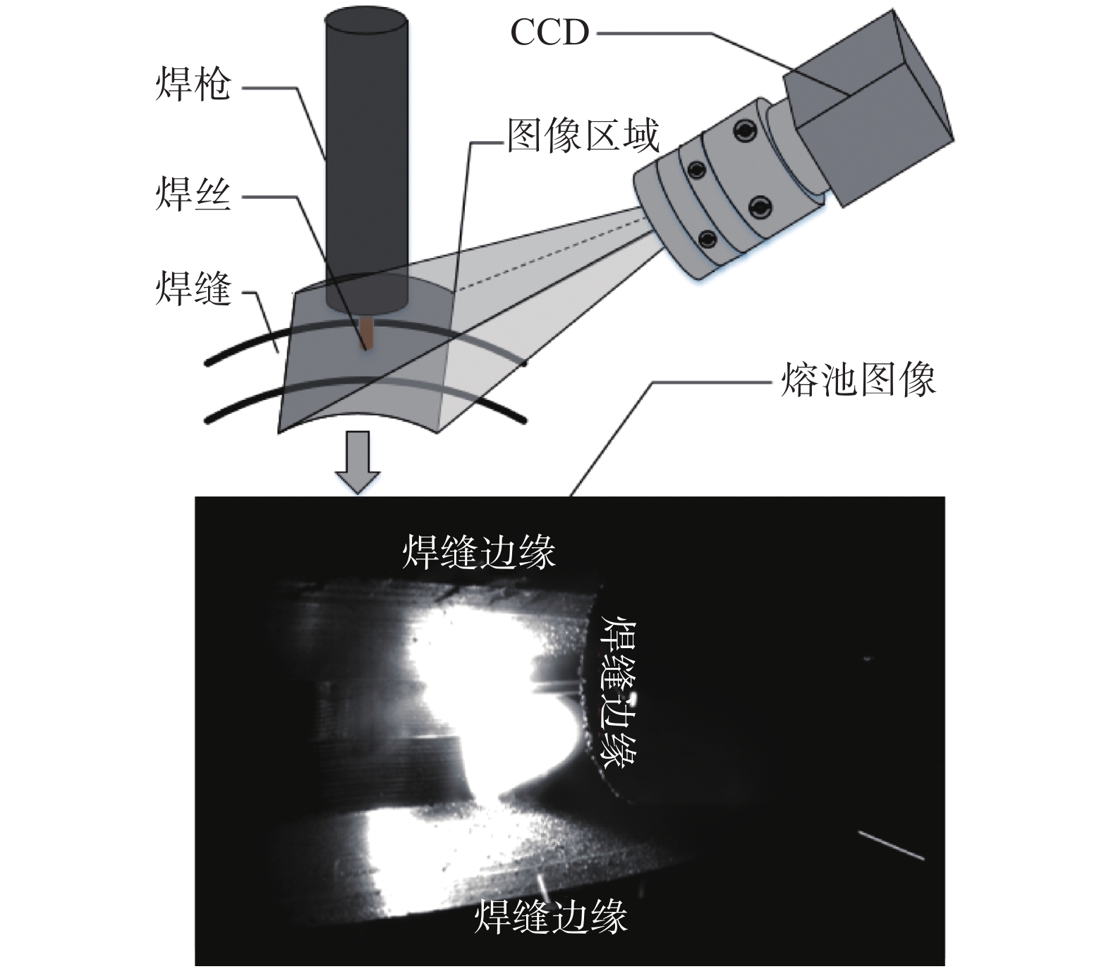
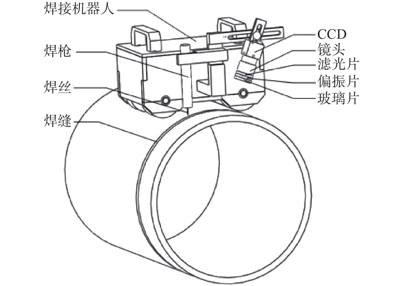
试验在自行研制的磁轮式焊接机器人上进行,试验系统如图1所示.该系统由焊接小车、控制系统、焊枪及焊接电源系统、视觉采集系统、计算机图像处理系统和试验钢管等组成.视觉采集系统由CCD摄像机、中心波长650 nm ± 5 nm的窄带滤光片、偏振片以及玻璃片组成,玻璃片的作用是阻挡焊渣飞溅,以免损坏偏振片.如图1所示,视觉采集系统与焊枪连接在同一个结构件上,因此,它们的运动方式是一致的,这样设计的优点在于视觉采集系统能够实时聚焦于焊枪末端,便于采集焊枪和焊缝的轮廓信息.
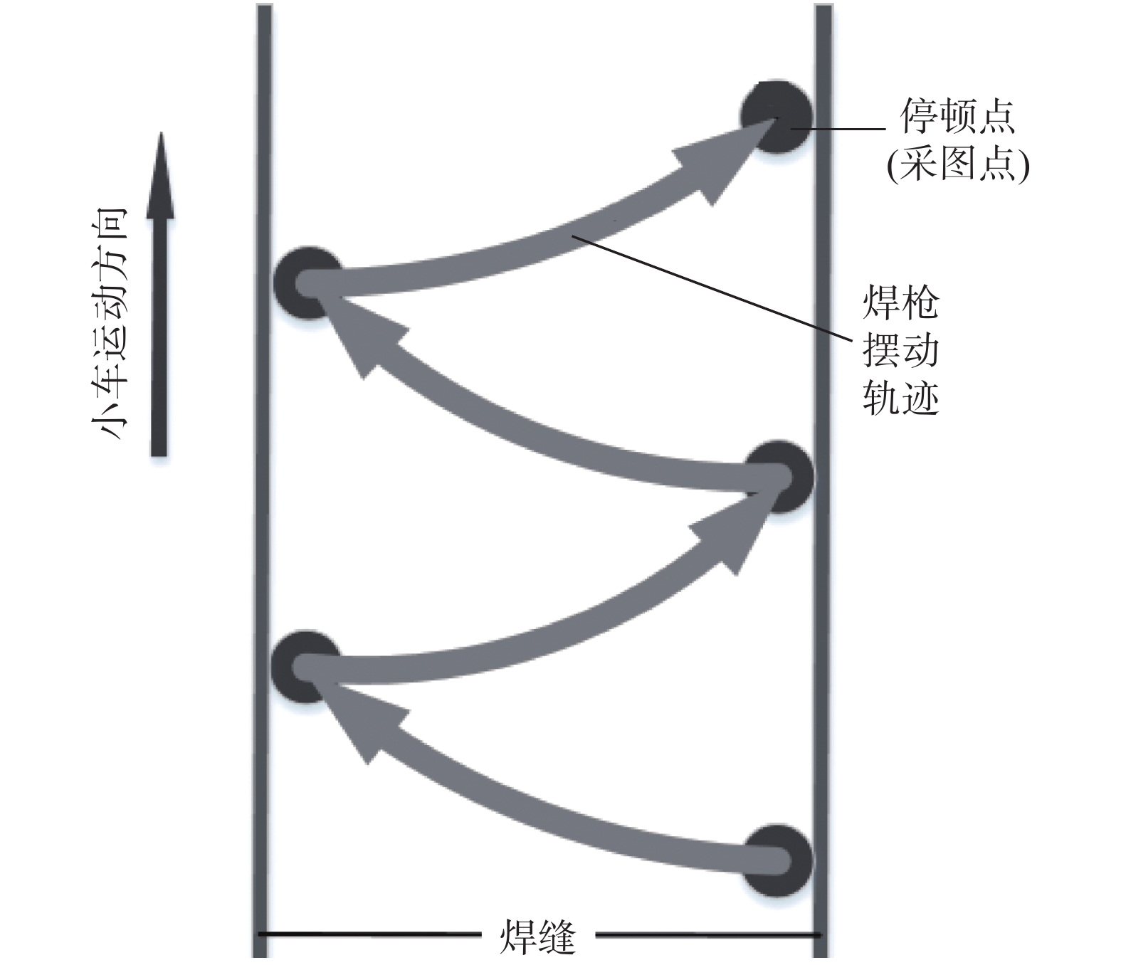
图2为焊枪运动轨迹示意图.焊枪在直线导轨驱动下左右摆动,根据焊接工艺要求,焊枪在运动到焊缝两侧边缘时,需停顿300 ~ 350 ms的时间以充分熔透管壁,故焊枪在左右摆动方向呈加减速运动状态.为了避免相机在运动状态下采集图像会造成物体存在拖影的现象,利用焊枪在焊缝两侧边缘需停顿的运动特性,将停顿点同时设定为采图点,使采集到的焊枪与焊缝轮廓图像较为清晰.为了更便于提取分析图像信息,文中只将右边停顿点设为采图点,即焊枪左右摆动一次作为一个采样周期,采样周期的长短由焊枪摆幅的大小决定.
1.2 目标成像模型与偏差测定原理
图3所示为目标成像模型,焊枪与相机的安装夹角在60º左右.因相机视角的原因,圆形焊枪在图像上呈椭圆形状,且因遮挡只存在半个椭圆形轮廓,弧形焊缝在图像上形似梯形,弧形焊缝边缘在短距离内趋近于直线.通过相机标定可以矫正图像使目标恢复原本形貌特征,但考虑到目前从事焊接行业工人的文化水平普遍不高,方便简洁的自动焊接设备更有利于推广,因此,除去了繁琐的相机标定环节,直接利用当前图像特征完成焊接偏差测定,同时也提高了图像处理速度和响应速度.
利用焊枪轮廓特征,可拟合出椭圆方程为
$$ A{x}^{2}+B{y}^{2}+Cx+Dy+E=0\;(A>0,B>0) $$ (1) 得到椭圆的中心点为
$$ {x}_{0}=\left(BE-2CD\right)/(4AD-{B}^{2}) $$ (2) $$ {y}_{0}=\left(BD-2AE\right)/(4AD-{B}^{2}) $$ (3) 即为焊枪的中心点
$ ({x}_{0},{y}_{0}) $ .焊缝边缘在短距离内可认为是直线,建立焊缝边缘的两条直线方程为$$ \left\{ \begin{array}{c}{A}_{1}x+{B}_{1}+{C}_{1}=0\\ {A}_{2}x+{B}_{2}+{C}_{2}=0 \\ \end{array} \right .$$ (4) 即得到了焊缝在图像中的位置.根据焊枪中心位置和焊缝边缘直线,则可计算出焊接偏差量.
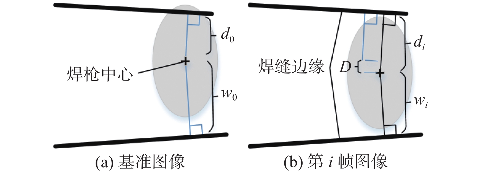
如图4所示为偏差测定原理示意图.以起弧后的第一张图像为基准,计算出焊枪中心(x0, y0)到焊缝上部边缘直线A1x+B1+C1 = 0的距离为d0,(x0, y0)到焊缝下部边缘直线A2x+B2+C2 = 0的距离为w0,即得到焊枪的摆幅为
$$ {W_0} = {d_0} + {w_0} $$ (5) 当焊接机器人运行到第
$ {i} $ 帧图像时,计算出对应的di和wi,摆幅为$$ {W_{{i}}} = {d_{{i}}} + {w_{{i}}} $$ (6) 焊枪位置像素偏差量为
$$ D = {d_{{i}}} - {d_0} $$ (7) 焊枪摆幅像素偏差量为
$$ W = {W_{{i}}} - {W_0} $$ (8) ![]() 图 4 偏差测定原理示意图Figure 4. Schematic of deviation detection principle. (a) reference image; (b) frame i image
图 4 偏差测定原理示意图Figure 4. Schematic of deviation detection principle. (a) reference image; (b) frame i image2. 熔池图像分析与聚类算法设计
2.1 熔池图像分析与处理
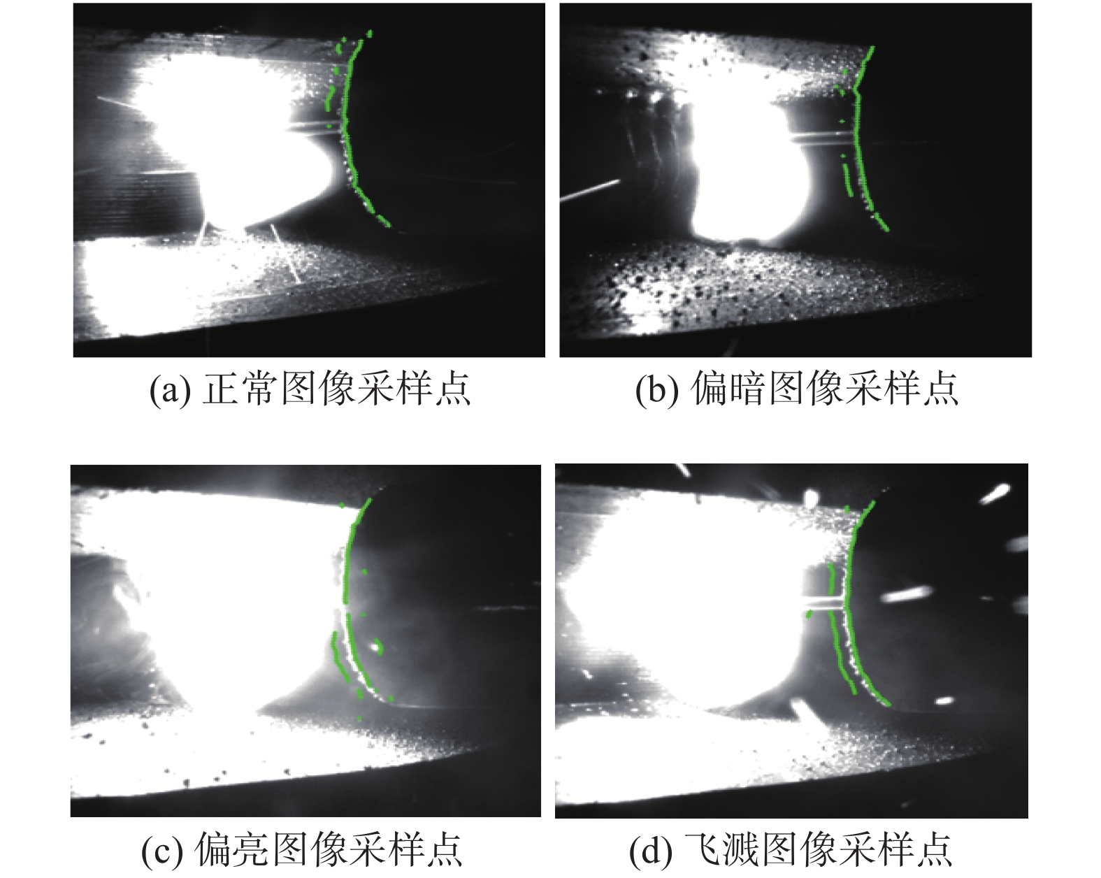
在采用GMAW方法焊接的过程中,由于电弧光明暗度的变化和焊渣飞溅的影响,焊缝和焊枪轮廓特征会受到不同程度的干扰,呈现出如图5所示的几种情况,导致采用一般的轮廓提取算法很难提取到关键的轮廓信息.
![]() 图 5 焊接过程中的熔池图像Figure 5. Molten pool image during welding. (a) regular image; (b) dark image; (c) bright image; (d) splash image
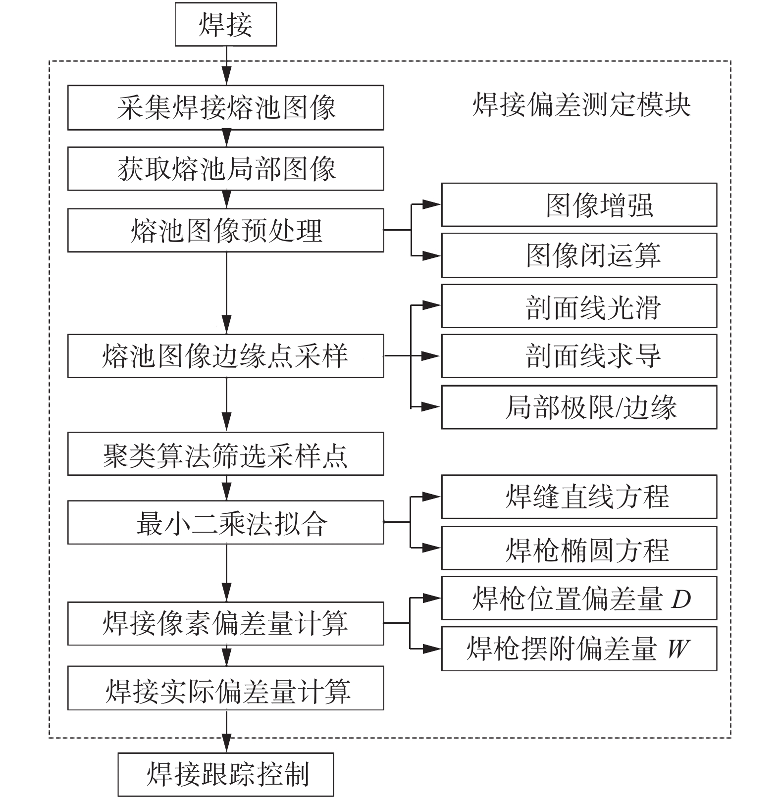
图 5 焊接过程中的熔池图像Figure 5. Molten pool image during welding. (a) regular image; (b) dark image; (c) bright image; (d) splash image对于熔池图像的不稳定性,文中设计了如图6所示的算法流程,完成了焊接偏差测定试验.在图6所示的算法流程中,关键的算法为熔池图像边缘点采样与聚类算法筛选采样点.对于边缘点采样,可在熔池图像中设置矩形窗选定目标区域.计算测量区域内垂直于剖面线上单位像素间隔的灰度平均值,代表剖面线上此点的灰度值;为消除干扰,可使用高斯滤波进行光滑处理;光滑处理后对剖面线求导获得极值,导数极值大于零的是灰度值由暗到亮(正向边缘,positive)变化的边缘点,导数极值小于零的是灰度值由亮到暗(负向边缘,negative)变化的边缘点.文中选取了正向边缘点作为目标轮廓的边缘采样点.
2.2 聚类算法设计
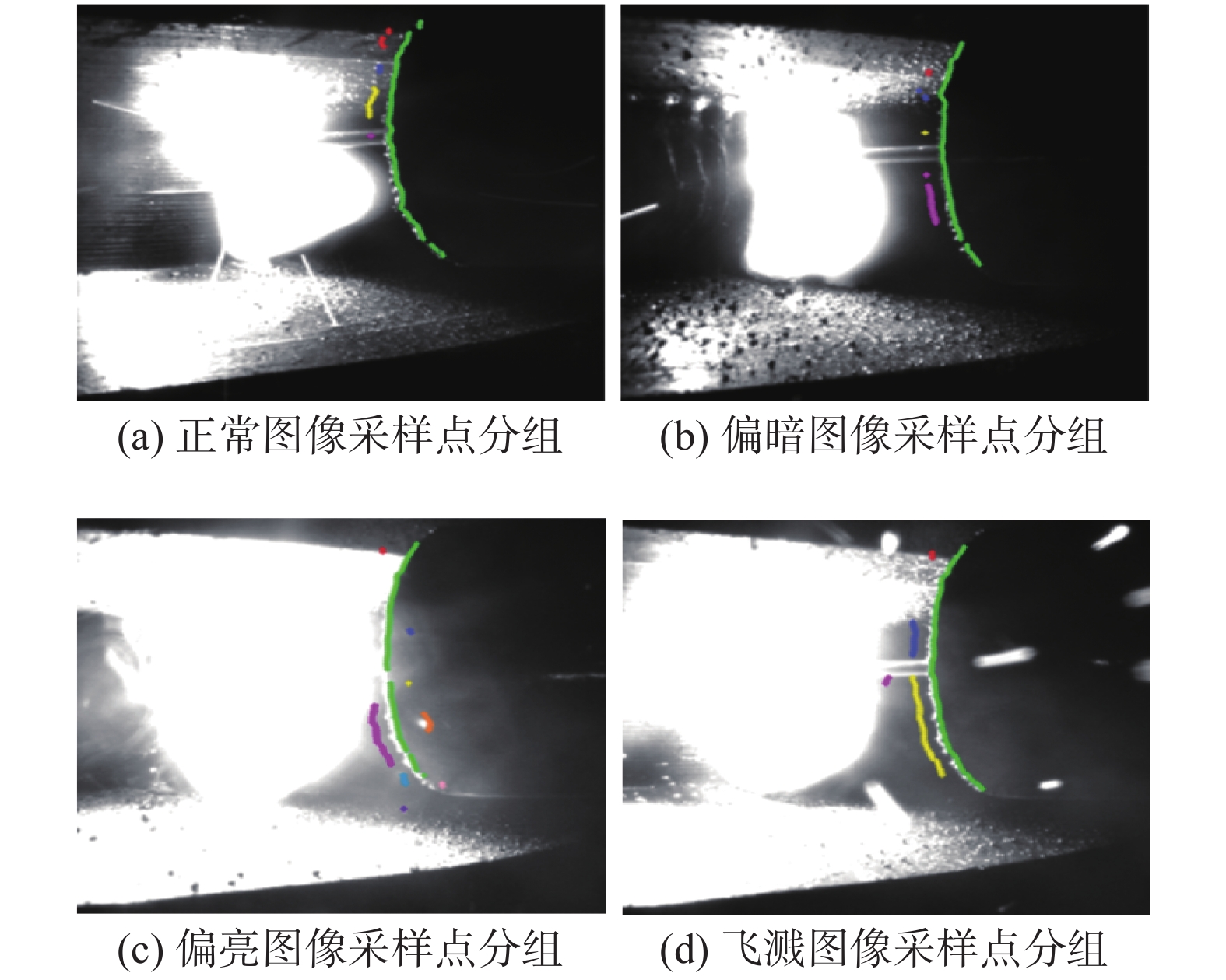
聚类算法在图像分析上有广泛的应用[9-10].聚类是把相似的对象通过静态分类的方法分成不同的组别或者更多的子集,使在同一个子集中的成员对象都有相似的一些属性,常见的特征是在坐标系中有更加短的空间距离.如图7所示,焊枪边缘经过采样后得到了较为明显且密集的边缘采样点,但同时也提取到同样满足条件的干扰点,因此,需要除去干扰点后再拟合椭圆方程以提高拟合精度.文中根据焊枪边缘采样点的分布规律,设计了一种快速方便的聚类算法.
![]() 图 7 熔池图像采样点分布图Figure 7. Sampling distribution of molten pool images. (a) sampling points of regular image; (b) sampling points of dark image; (c) sampling points of bright image; (d) sampling points of splash image
图 7 熔池图像采样点分布图Figure 7. Sampling distribution of molten pool images. (a) sampling points of regular image; (b) sampling points of dark image; (c) sampling points of bright image; (d) sampling points of splash image聚类算法的核心步骤为同类型对象的判别,判别条件设计的优劣决定了分组的精度.在该聚类算法中使用欧式几何中的距离和方向两个特征,再结合边缘采样点的分布规律设置合理的阈值,判别出两个对象是否为同一子集.设两个焊枪边缘采样点
${A}\left({x}_{1},{y}_{1}\right),{B}({x}_{2},{y}_{2})$ ,当A和B满足式(9)条件时$$ \left \{ \begin{array}{c}\sqrt{{({x}_{2}-{x}_{1})}^{2}+{({y}_{2}-{y}_{1})}^{2}} < {D}_{T}\\ \left|{\mathrm{tan}}^{-1}\left({y}_{2}-{y}_{1}\right)/\left({x}_{2}-{x}_{1}\right)\right| < {\theta }_{T}\end{array}\right. $$ (9) 式中:
$ {D}_{T} $ 为A,B两点间的距离阈值;$ {\theta }_{T} $ 为A,B两点间角度阈值,即A和B为同一子集. 该聚类算法的实现步骤如下.(1) 算法开始,逐行读取采样点.
(2) 第一行采样点的个数为n,则创建
${C}_{1}, {C}_{2}$ ,$ {C}_{3},\cdots,{C}_{n} $ 个子集,记为$ {C}_{i} $ .(3) 读取第二行采样点,逐个采样点均使用式(6)计算与
$ {C}_{i} $ 的归属关系,满足条件则为$ {C}_{i} $ 子集的成员,与$ {C}_{i} $ 都不满足条件则重新创建子集$ {C}_{n+1} $ ,以此类推,新子集为$ {C}_{n+2},{C}_{n+3},\cdots $ ,同样记为$ {C}_{i} $ .(4)
$ \cdots \cdots $ ,读取第i行采样点,执行步骤(2)操作.(5) 采样点读取并计算完毕,算法结束.
图8为熔池图像边缘采样点经过聚类算法处理后的结果显示图,不同颜色的采样点表示不同的分组.从分组结果可以看出,此聚类算法对该环境下的边缘采样点有很好的分组效果,能够有效的去除干扰点的影响.
![]() 图 8 聚类算法处理结果Figure 8. Processing results of clustering algorithm. (a) sampling points grouping of regular images; (b) sampling points grouping of dark images; (c) sampling points grouping of bright images; (d) sampling points grouping of splash images
图 8 聚类算法处理结果Figure 8. Processing results of clustering algorithm. (a) sampling points grouping of regular images; (b) sampling points grouping of dark images; (c) sampling points grouping of bright images; (d) sampling points grouping of splash images3. 替代误差分析与焊接偏差测定分析
3.1 替代误差分析
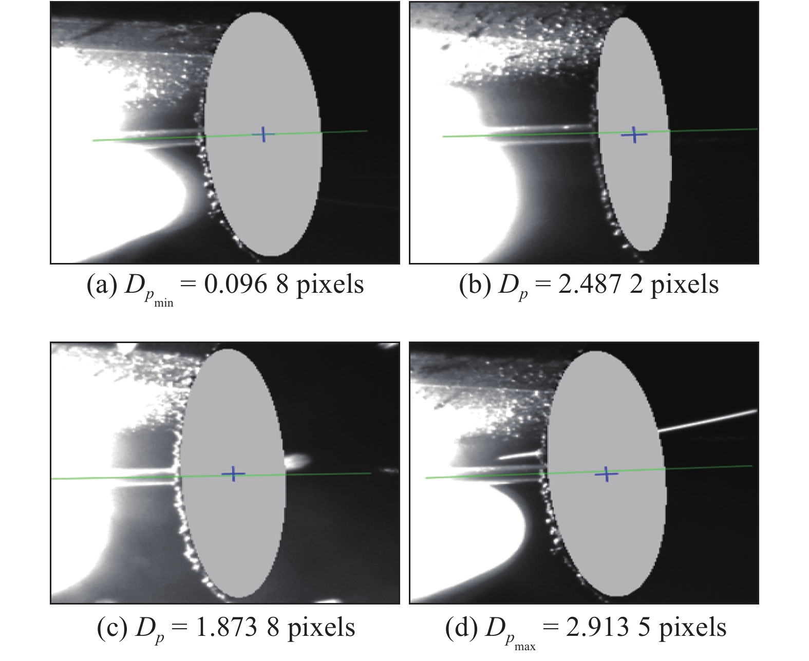
在该替代方法中,焊枪与焊丝相对位置固定且运动规律具有一致性,理论上该替代方法引入的误差量为固定值,可以通过补偿进行修正.但在焊枪椭圆方程拟合的过程中,因熔池图像明暗不均且受干扰严重,导致焊枪边缘采样点数量不一致,因此,拟合出的椭圆大小和中心位置有一定的偏差,这就给焊枪替代焊丝的方法引入了误差量.
如图9所示,焊枪椭圆中心与焊丝轴线存在着一定的偏差量,该偏差量为Dp,即焊枪椭圆中心到焊丝轴线的距离,距离的单位为像素值.
![]() 图 9 替代误差显示图Figure 9. Substitution error. (a) Dpmin = 0.096 8 pixels; (b) Dp = 2.487 2 pixels; (c) Dp = 1.873 9 pixels; (d) Dpmax = 2.913 5 pixels
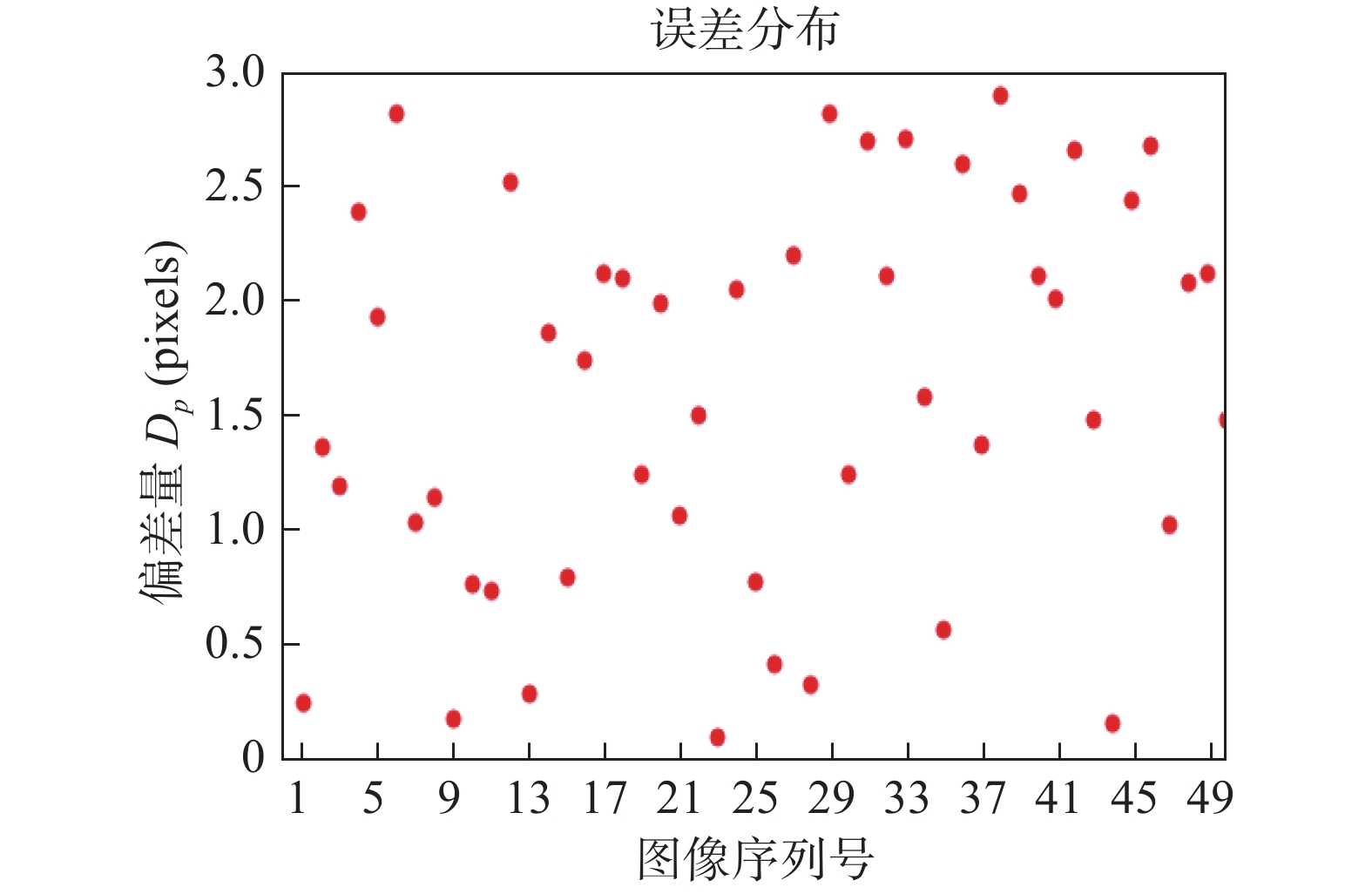
图 9 替代误差显示图Figure 9. Substitution error. (a) Dpmin = 0.096 8 pixels; (b) Dp = 2.487 2 pixels; (c) Dp = 1.873 9 pixels; (d) Dpmax = 2.913 5 pixels在试验中,从200帧图像中选取了50帧能够同时提取到焊枪与焊丝位置的熔池图像,计算出该50帧熔池图像中焊枪椭圆中心到焊丝轴线的距离,其替代误差分布如图10所示.在50帧替代误差数据中,最大误差值为2.913 5 pixels,最小误差值为0.096 8 pixels.经测量,焊接中焊丝直径为1.2 mm,焊丝在图像中的像素数为17,由此可得1像素为0.070 6 mm. 因此,焊枪替代焊丝的误差范围为0 ~ 0.2 mm,满足实际焊接中对精度的要求.
3.2 焊接偏差测定分析
为了检验该替代方法对焊接偏差量测定的精度,试验在经车床加工的焊缝上进行,车床加工的焊缝宽度均匀且焊缝较直,属于理想的试验环境,可排除一些干扰因素,有利于对试验数据的分析.试验过程中,不需要对焊接机器人和焊枪做任何纠偏操作,使焊接机器人处于一个自由运动的状态.由于焊接机器人的摆放与焊缝呈一定的角度,因此,自由运动状态下焊接机器人会逐渐向一边偏移.由于车床加工的焊缝较直,可以推断出焊枪中心同样会向一边偏移,且偏移方向和焊接机器人偏移方向一致.
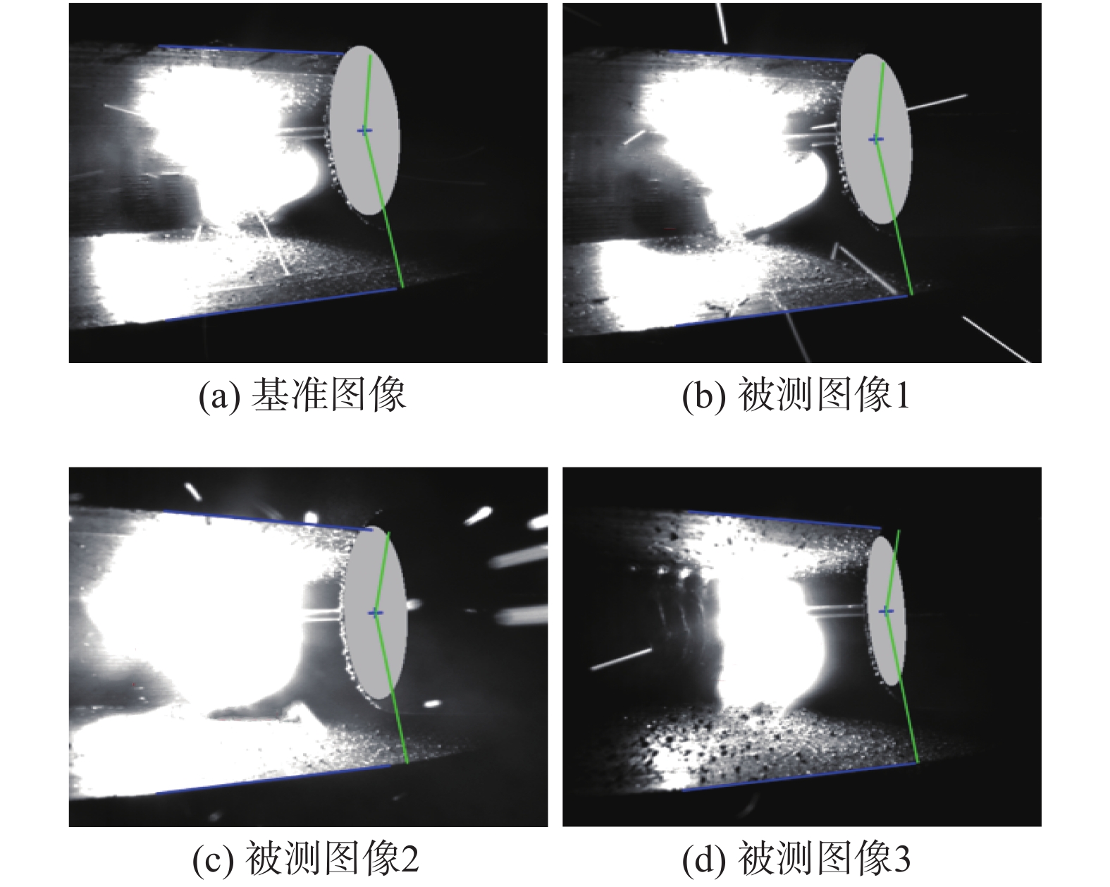
文中选取了焊接过程中一段连续的21帧熔池图像进行数据分析,图像处理结果如图11所示,焊接偏差量测定数值如表1所示. 以第1帧熔池图像为基准图像,后20帧图像对比基准图像进行焊接偏差量的测定,部分处理结果如图11b ~ 图11d所示.
![]() 图 11 焊接偏差量测定结果Figure 11. Detection results of welding deviation. (a) benchmark image; (b) tested image 1; (c) tested image 2; (d) tested image 3表 1 焊接偏差量测定数值Table 1. Measurement value of welding deviation
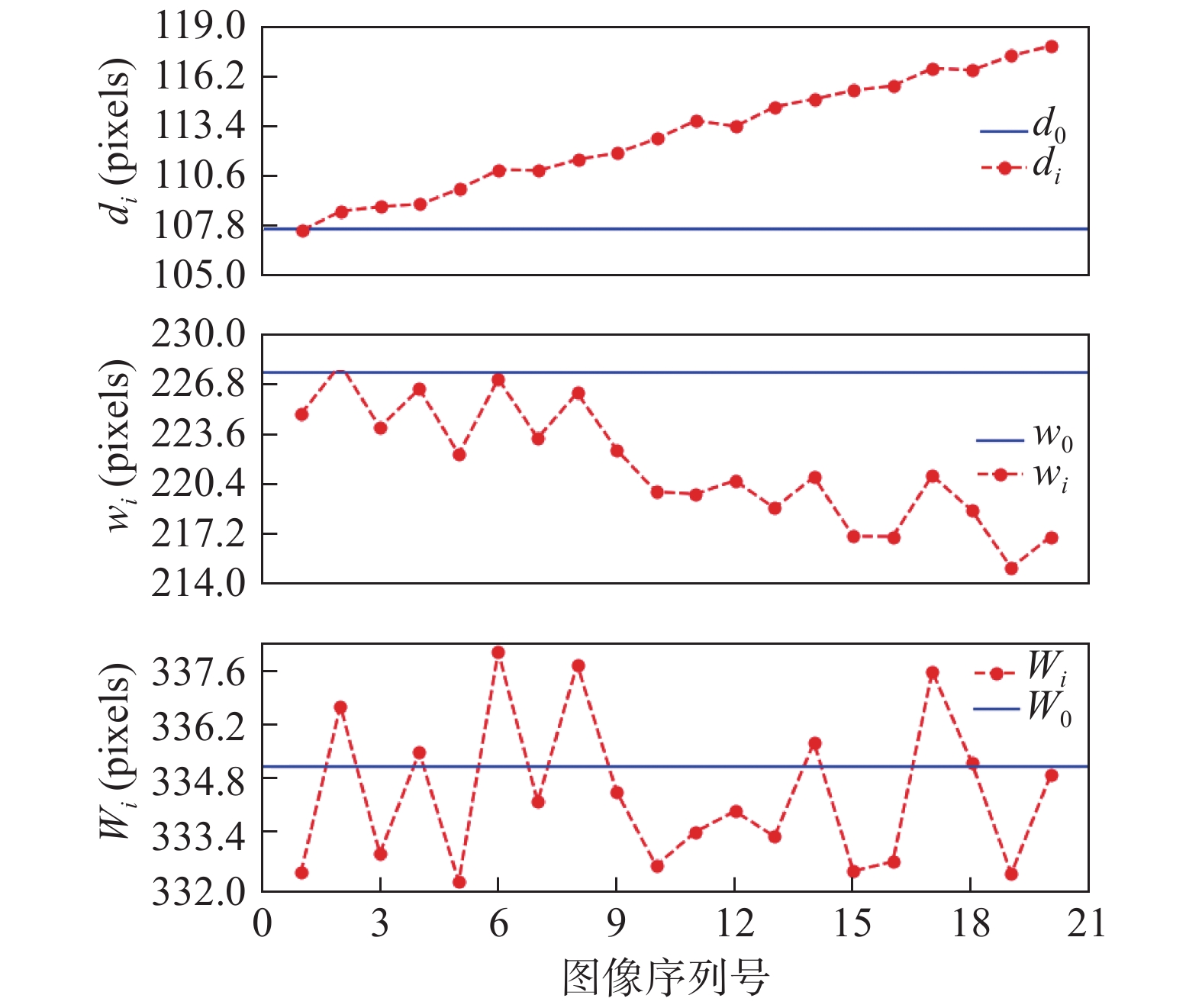
图 11 焊接偏差量测定结果Figure 11. Detection results of welding deviation. (a) benchmark image; (b) tested image 1; (c) tested image 2; (d) tested image 3表 1 焊接偏差量测定数值Table 1. Measurement value of welding deviation选取图像 中心到上部距离d0(pixels) 第i帧图像到上部距离di(pixels) 中心到下部距离w0(pixels) 第i帧图像到下部距离wi(pixels) 焊枪摆幅W0(pixels) 第i帧图像摆幅Wi(pixels) 基准图像 107.708 227.544 335.252 被测图像1 109.621 225.207 334.828 被测图像2 116.189 216.75 332.939 被测图像3 117.052 219.04 336.092 焊缝偏差量变化如图12所示. 在图12中水平线表示基准图像中的测定值,曲线表示当前图像的测定值.焊枪摆幅实际偏差Wr的测定可以从Wi中得出. 实际值为−0.207 mm ≤ Wr ≤ 0.205 mm.因为机械加工的焊缝宽度较为均匀,所以Wr数值较小且较稳定,这验证了该替代方法对焊枪摆幅实际偏差量测定的可靠性.di为焊枪中心位置距离焊缝上边缘的测定值,从图中di曲线的走势可以看出,di逐渐远离基准值d0,说明焊枪中心在向同一方向逐渐偏离,这验证了上文自由运动状态下焊枪中心会随着焊接机器人向同一方向逐渐偏移的推断.焊枪位置实际偏差量Dr ,计算公式为
$$ {D_{{r}}} = {\rm{ }}\left( {{d_{i}} - {d_0}} \right) \times 0.0{\rm{ }}70\;6 $$ (10) 例如第12帧图像中的Dr为(113.397 − 107.708) × 0.070 6 = 0.402 mm.
4. 结论
(1) 提出了一种定位焊枪中心来替代定位焊丝尖端的快速焊接偏差测定方法,并对该方法进行了试验验证.经分析替代误差数据和焊接偏差数据可知,该替代方法在实现上具有可行性,且操作简单便于实现.
(2) 设计了一种实现简单且处理快速的聚类算法,对试验中的采样点具有较高的分组精度,能够提高椭圆和直线的拟合精度.该聚类算法同样适合于与文中采样点特征相类似的数据的分组.
-
![]()
图 4 偏差测定原理示意图
Figure 4. Schematic of deviation detection principle. (a) reference image; (b) frame i image
![]()
图 5 焊接过程中的熔池图像
Figure 5. Molten pool image during welding. (a) regular image; (b) dark image; (c) bright image; (d) splash image
![]()
图 7 熔池图像采样点分布图
Figure 7. Sampling distribution of molten pool images. (a) sampling points of regular image; (b) sampling points of dark image; (c) sampling points of bright image; (d) sampling points of splash image
![]()
图 8 聚类算法处理结果
Figure 8. Processing results of clustering algorithm. (a) sampling points grouping of regular images; (b) sampling points grouping of dark images; (c) sampling points grouping of bright images; (d) sampling points grouping of splash images
![]()
图 9 替代误差显示图
Figure 9. Substitution error. (a) Dpmin = 0.096 8 pixels; (b) Dp = 2.487 2 pixels; (c) Dp = 1.873 9 pixels; (d) Dpmax = 2.913 5 pixels
![]()
图 11 焊接偏差量测定结果
Figure 11. Detection results of welding deviation. (a) benchmark image; (b) tested image 1; (c) tested image 2; (d) tested image 3
表 1 焊接偏差量测定数值
Table 1 Measurement value of welding deviation
选取图像 中心到上部距离d0(pixels) 第i帧图像到上部距离di(pixels) 中心到下部距离w0(pixels) 第i帧图像到下部距离wi(pixels) 焊枪摆幅W0(pixels) 第i帧图像摆幅Wi(pixels) 基准图像 107.708 227.544 335.252 被测图像1 109.621 225.207 334.828 被测图像2 116.189 216.75 332.939 被测图像3 117.052 219.04 336.092  下载: 导出CSV
-
[1] Xu Y L, Zhang J Y, Ding M Y, et al. The acquisition and processing of real time information for height tracking of robotic GTAM process by arc sensor[J]. The International Journal of Advanced Manufacturing Technology, 2013, 65(5): 1031 − 1043.
[2] 李晓延, 武传松, 李午申. 中国焊接制造领域学科发展研究[J]. 机械工程学报, 2012, 48(6): 19 − 31. doi: 10.3901/JME.2012.06.019 Li Xiaoyan, Wu Chuansong, Li Wushen. Study on the progress of welding science and technology in China[J]. Journal of Mechanical Engineering, 2012, 48(6): 19 − 31. doi: 10.3901/JME.2012.06.019
[3] 洪波, 言浚光, 阳佳旺, 等. 一种用于焊缝跟踪的电容式传感器[J]. 焊接学报, 2014, 35(2): 55 − 58. Hong Bo, Yan Junguang, Yang Jiawang, et al. A capacitive sensor for automatic weld seam tracking[J]. Transactions of the China Welding Institution, 2014, 35(2): 55 − 58.
[4] Amruta Rout, Deepak B B V L, Biswal B B. Advances in weld seam tracking techniques for robotic welding: A review[J]. Robotics and Computer Integrated Manufacturing, 2019, 56(4): 12 − 37.
[5] Hong Yuxiang, Du Dong, Pan Jiluan, et al. Seam-tracking based on dynamic trajectory planning for a mobile welding robot[J]. China Welding, 2019, 28(4): 46 − 50.
[6] 张鹏贤, 张国强, 韦志成, 等. 坡口及焊缝表面三维轮廓的激光视觉测量[J]. 焊接学报, 2017, 38(12): 85 − 89. doi: 10.12073/j.hjxb.20160331003 Zhang Pengxian, Zhang Guoqiang, Wei Zhicheng, et al. Laser vision measurement for 3D surface outline of groove and weld[J]. Transactions of the China Welding Institution, 2017, 38(12): 85 − 89. doi: 10.12073/j.hjxb.20160331003
[7] Zhu Yanjun,Wu Zhisheng, Li Ke, et al. Welding deviation detection method based on weld pool image contour features[J]. China Welding, 2019, 28(2): 35 − 44.
[8] 邹勇, 李运华, 蒋力培, 等. 基于熔池图像尖端特征规律的焊接偏差测定方法[J]. 焊接学报, 2015, 36(8): 18 − 22. Zou Yong, Li Yunhua, Jiang Lipei, et al. Method of detecting weld deviation based on the image feature of molten pool's edge[J]. Transactions of the China Welding Institution, 2015, 36(8): 18 − 22.
[9] Azimi R, Ghayekhloo M, Ghofrani M, et al. A novel clustering algorithm based on data transformation approaches[J]. Expert Systems with Applications, 2017, 76: 59 − 70. doi: 10.1016/j.eswa.2017.01.024
[10] 李大华, 赵辉, 于晓. 基于改进谱聚类的重叠绿苹果识别方法[J]. 光谱学与光谱分析, 2019, 39(9): 2974 − 2981. Li Dahua, Zhao Hui, Yu Xiao. Overlapping green apple recognition based on improved spectral clustering[J]. Spectroscopy and Spectral Analysis, 2019, 39(9): 2974 − 2981.
-
期刊类型引用(4)
1. 邓智超,颜润明,杨蕙同,陈浩林,赖锦祥,雷亮. 基于改进残差网络的多视图焊点缺陷检测. 焊接学报. 2022(03): 56-62+116 .  本站查看
本站查看
2. 何晓娅,袁彬,雷经发,吴路路,董方方. 区域产业需求导向的创新型人才培养模式研究——以安徽省机器人专业为例. 教育教学论坛. 2022(36): 6-10 . 百度学术
3. 柯希林,王中任,刘海生,王小刚. 基于单目主被动视觉结合的焊接偏差检测方法. 激光与红外. 2021(11): 1519-1525 . 百度学术
4. 张天一,朱志明,朱传辉. 基于视觉与重力融合传感的焊枪位姿反馈控制. 焊接学报. 2021(11): 1-7+97 . 本站查看
其他类型引用(0)


计量
- 文章访问数: 396
- HTML全文浏览量: 38
- PDF下载量: 42
- 被引次数: 4
