
Rapid fatigue strength assessment of SUS301L-Q235B dissimilar materials spot-welded joint based on infrared thermography
-
摘要: 借助高性能红外热像仪对SUS301L-Q235B异种材料点焊接头的SUS301L不锈钢侧熔核及塑性环表面局部热点进行监测,建立了异种材料点焊接头温升斜率与疲劳极限间的定量关系,提出了一种基于温升斜率转折点预测异种材料点焊接头疲劳极限的方法. 结果表明,SUS301L-Q235B异种材料点焊接头向Q235B侧发生了较严重的熔核偏移,导致不锈钢侧承载能力降低;点焊接头在高频循环剪切拉伸作用下,SUS301L不锈钢侧熔核及塑性环表面热点表现出“4个阶段”的温度演化特征;利用红外热像法预测的疲劳极限为5.569 kN,采用传统阶梯法试验获得的疲劳极限为5.875 kN,预测值与试验值之间的误差为5.21%,具有较高的一致性. 所提出的疲劳极限快速预测方法能够克服传统疲劳试验方法的局限性,实现异种材料点焊接头疲劳极限的非接触、非破坏快速预测,具有重要的工程意义和科研价值.Abstract: In this paper, with the help of high performance infrared thermal imager, local hot spots of nugget and plastic ring on the side of SUS301L stainless steel of the SUS301L-Q235B dissimilar materials spot-welded joint was monitored. And the quantitative relationship between the temperature rise slope and the fatigue limit of the welding joint of dissimilar materials was established. Then, a method to predict the fatigue limit of the spot-welded joint of dissimilar materials based on the tipping point of temperature rise. The results show that a serious nugget migration generates on the Q235B side of SUS301L-Q235B dissimilar materials spot-welded joint, which results in reduction of the carrying capacity of stainless steel. Under the action of high frequency shear tensile, the "four stages" temperature evolution characteristics are presented. The fatigue limit predicted by infrared thermography was 5.569 kN. The fatigue limit obtained by the traditional staircase method was 5.875 kN. The error between the predicted value and the test value was 5.21%, which presents a high concordance. The rapid fatigue limit prediction proposed in this paper can overcome the limitations of the traditional fatigue test method and realize non-contact and non-destructive prediction of spot-welded joint fatigue limit of dissimilar materials, which has important engineering significance and research value.
-
Keywords:
- infrared thermography /
- dissimilar materials /
- fatigue strength /
- rapid assessment /
- spot welding
-
0. 序言
NiCrMoV低合金钢作为一种超高强钢,综合性能良好,在船舶、压力容器等领域应用广泛[1-2]. 但由于此类高强钢具有较大的淬硬倾向,焊接时容易产生冷裂纹. 且随着强度的提高,其焊接冷裂敏感性就越大,还易导致焊接接头脆化[3-5].
对于NiCrMoV低合金高强钢焊接,除了采用预热措施之外,往往采用奥氏体焊材低强匹配接头抑制冷裂纹的产生,但是会大幅降低高强钢接头强度. 现有的奥氏体焊丝如316L或304不锈钢焊材,得到的焊缝接头强度仅为500 ~ 600 MPa. 因此采用高强度奥氏体焊材焊接超高强钢意义重大. 李大用等人[6]采用高铬镍奥氏体焊丝焊接低合金高强钢,其中氮含量约为0.1%,焊缝主要由树枝状奥氏体组成,无裂纹,接头强度可达800 MPa. 在抑制裂纹的同时可保证强度.
在奥氏体不锈钢体系中,高氮钢以氮部分或全部代替镍合金而形成固溶强化的奥氏体不锈钢,强度可达1 000 MPa[7]. 因此文中拟采用高氮奥氏体焊丝作为填充材料进行超高强钢熔化极气体保护焊(gas metal arc welding, GMAW). 目前对于此类焊丝GMAW工艺研究较少. 针对8 mm厚超高强钢板对接,初步探索了利用高氮钢焊丝GMAW工艺,分析在60°和90°不同的坡口角度下接头组织和力学性能,为超高强钢焊接提供了新思路.
1. 试验方法
试验使用直径1.0 mm的高氮奥氏体钢焊丝作为填充材料,超高强钢板为母材,试板尺寸300 mm × 200 mm × 8 mm. 所用焊丝和母材成分如表1所示.
表 1 焊丝与母材化学元素组成(质量分数,%)Table 1. Chemical component of wire and substrate材料 C Ni Cr Mo Mn Si N 焊丝 0.071 2.32 21.59 1.21 16.95 — 0.79 母材 0.32 1.8 1.0 0.7 1.2 0.4 — 采用CMT + P焊接模式,先正面焊一道,然后背部清根,反面焊一道. 工艺参数为正面送丝速度10 m/min,反面送丝速度9.5 m/min,焊接速度4 mm/s. 保护气体为93.5% Ar + 1.5% O2 + 5% N2,气体流量20 L/min. 坡口形式分别为60°和90°坡口,上下深度比为5∶3. 考虑到焊枪的可达性及减少侧壁未熔合,间隙为3 mm. 拉伸试件按国家标准GBT 2651—2008《焊接接头拉伸试验方法》加工.
2. 试验结果分析
2.1 焊缝宏观形貌
图1是超高强钢高氮奥氏体焊丝熔化极电弧焊接的焊缝宏观形貌和接头纵向截面宏观形貌. 接头成形良好,焊材与母材之间形成冶金结合,接头纵向截面未见气孔、裂纹等缺陷.
2.2 显微组织分析
图2~图4为不同坡口焊缝与热影响区组织形貌. 热影响区可分为明显的粗晶区和细晶区,均为马氏体组织,如图2a,2b,3a,3b所示,对硬度影响较大. 焊缝的组织主要是被奥氏体基体所包围的铁素体树枝晶,且铁素体枝晶很密集. 除此之外,在枝晶中间还有一些“粒状”铁素体散乱的分布在整个金相中,被奥氏体基体所包围,如图2c,3c所示. 两种坡口的焊缝金属和母材金属在结合处的“白亮带”区域有着明显的模糊状态,有相互渗透的现象,并观察到该区是奥氏体与马氏体的混合组织,如图4所示.
![]() 图 2 60°坡口不同区域显微组织Figure 2. Microstructure of different position with groove of 60°. (a) martensite coarse crystal structure of 60°;(b) martensite fine crystal structure of 60°; (c) weld austenite structure of 60°
图 2 60°坡口不同区域显微组织Figure 2. Microstructure of different position with groove of 60°. (a) martensite coarse crystal structure of 60°;(b) martensite fine crystal structure of 60°; (c) weld austenite structure of 60°![]() 图 3 90°坡口不同区域显微组织Figure 3. Microstructure of different position with groove of 90°. (a) martensite coarse crystal structure of 90°;(b) martensite fine crystal structure of 90°; (c) weld austenite structure of 90°
图 3 90°坡口不同区域显微组织Figure 3. Microstructure of different position with groove of 90°. (a) martensite coarse crystal structure of 90°;(b) martensite fine crystal structure of 90°; (c) weld austenite structure of 90°两种坡口接头熔合线附近热影响区组织和焊缝组织基本一致. 不同的是,90°坡口焊缝附近热影响区马氏体组织较60°的更细小,同时90°坡口热影响区马氏体和奥氏体的混合组织区的范围比60°的小. 在相同的热输入参数下90°坡口相比60°坡口,不仅能让电弧充分达到焊缝底部,且在相同的深度下,90°坡口与电弧的接触面积更大,熔池凝固快. 60°坡口情况则相反,熔池存在时间更长,这个过程提供了晶粒继续长大的条件,因此60°坡口热影响区马氏体和奥氏体混合组织区较90°的大,相应的马氏体组织也较为粗大. 同时,60°坡口焊缝区也受到影响,组织相对粗大.
如图5所示,在200 ~ 240 μm的热影响区到焊缝的过渡区,核心元素都有一个线性变化的过程,过渡区的存在说明焊缝金属和母材金属有着充分的冶金结合. 但如图4所示,90°坡口的渗透区域相对60°坡口的更大,且相对更均匀.
2.3 显微硬度
如图6所示1和2分别为60°坡口和90°坡口的硬度分布,硬度取样区域线见图1,两种硬度分布是一致的. 硬度按从母材-热影响区-焊缝的顺序依次测量,经过的组织依次为母材马氏体组织-马氏体细晶组织-混合组织-奥氏体组织. 根据图6各组试样的横向硬度分布可知,硬度最高区域主要集中在2.5 ~ 4 mm和7.5 ~ 9 mm的区域内,该区域的维氏硬度在450 ~ 590 HV之间,60°坡口该区硬度平均值为508 HV,90°坡口该区硬度平均值为536 HV. 在硬度显微镜下观测该硬度较高的区域主要为马氏体细晶区. 其中马氏体细晶区的硬度值均在500 HV及以上,平均可达530 HV;在热影响区到焊缝区的过渡区(3.5 ~ 4 mm),该区组织硬度相对马氏体细晶区有一个下降过程,主要是因为该区是马氏体组织和奥氏体组织的混合组织,该区组织相对不均匀,所以该区域的硬度有个下降过程. 由图6可知,硬度最低的区域主要为4.5 ~ 7 mm区域,均在300 HV以下,平均硬度仅在275 HV左右. 该区域是焊缝区,其组织主要以奥氏体为基体的树枝状铁素体晶粒组织,故硬度较低,两种坡口在该区硬度值相差不大.
2.4 拉伸试验
从图7可以看出,60°坡口试样主要是从焊缝位置断裂,部分沿熔合线附近位置断裂,90°坡口试样主要沿熔合线附近位置断裂. 每个试样均有颈缩现象发生. 如表2所示,采用高氮奥氏体钢焊丝获得的接头平均抗拉强度可达850 MPa,该强度是在90°坡口下获得的. 60°坡口接头的抗拉强度则与之相差较大,仅为690 MPa. 对于不同坡口接头的拉伸力学性能变化与微观组织的某些区域的大小以及晶粒的大小有关. 在相同的坡口深度下,60°坡口侧壁与电弧的接触面积更小,其熔池存在时间更长,该过程为焊缝组织晶粒继续长大提供了条件,因此60°坡口焊缝区组织晶粒更粗大,其拉伸性能较低. 对于90°坡口其与电弧的接触面积更大,其熔池凝固快,晶粒相对较小,因此强度更高,并且由于混合组织区较宽,该区域成分介于母材和焊丝之间,得到的性能相对较低,所以90°坡口多断在此处.
表 2 接头抗拉强度 (MPa)Table 2. Tensile strength of joint坡口角度 试样1 试样2 试样3 平均抗拉强度 60° 720 678 672 690 90° 887 834 829 850 3. 结论
(1) 采用高氮奥氏体丝材进行超高强钢GMAW工艺,可以获得成形良好的焊接接头.
(2) 高氮钢焊缝金属和超高强钢母材金属在接头熔合线处有着明显的“白亮带”存在,有相互渗透的现象,说明焊材和母材有着充分的冶金结合.
(3) 采用上述工艺中60°坡口进行焊接,接头热影响区马氏体组织晶粒较大,且马氏体、奥氏体混合组织过渡区小;而90°坡口焊接接头热影响区马氏体组织晶粒更细小,且马氏体、奥氏体混合组织过渡区较大.
(4) 采用高氮奥氏体焊丝进行GMAW焊接,90°坡口可获得接头抗拉强度(850 MPa)高于60°坡口接头抗拉强度(690 MPa). 90°坡口试样马氏体细晶区硬度平均值为536 HV,高于60°坡口试样(508 HV).
-
![]()
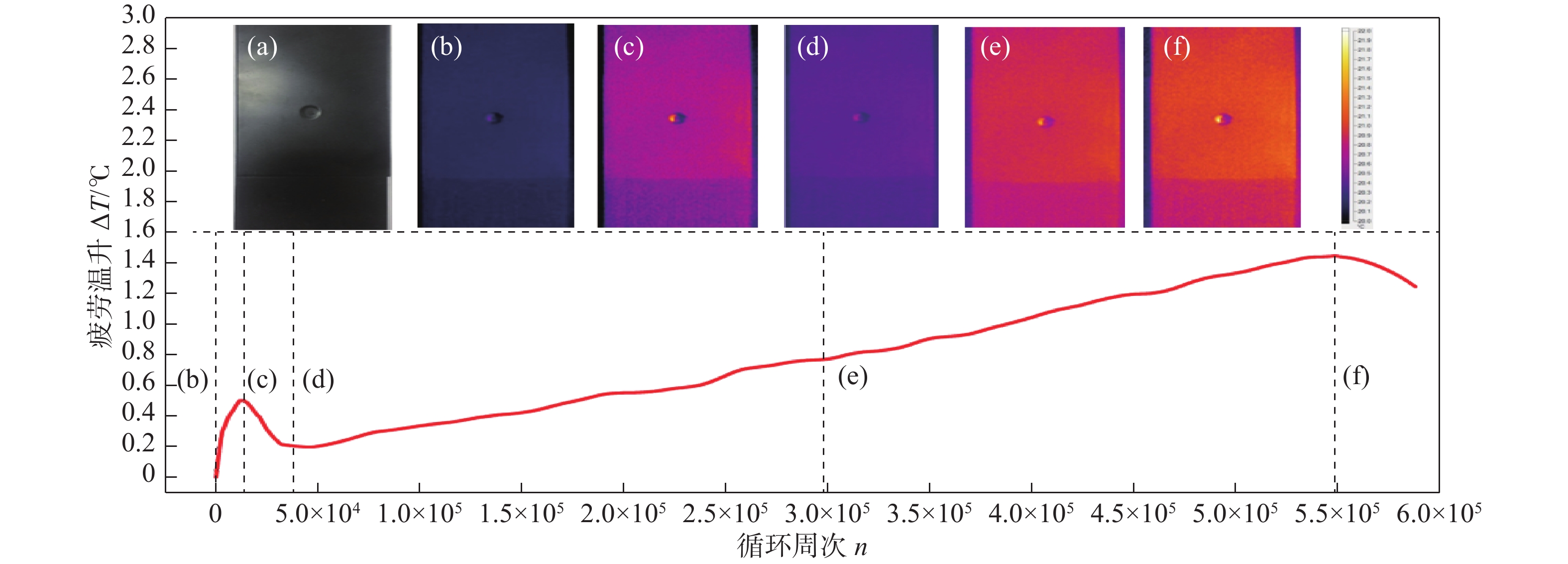
图 3 载荷水平为7.0 kN的试样疲劳温升与循环周次关系曲线图
Figure 3. Relationship curve of fatigue temperature revolution versus cycles under the load level of 7.0 kN
![]()
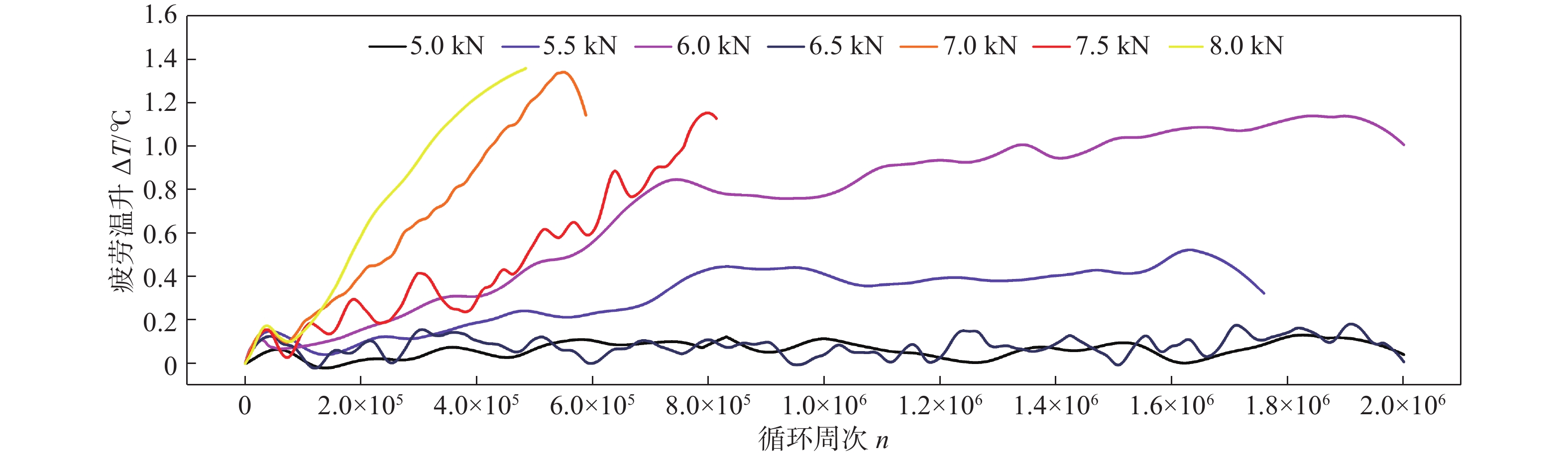
图 4 七组载荷水平下疲劳温升与循环周次关系曲线图
Figure 4. Relationship curve of fatigue temperature revolution versus cycles of the seven load levels
![]()
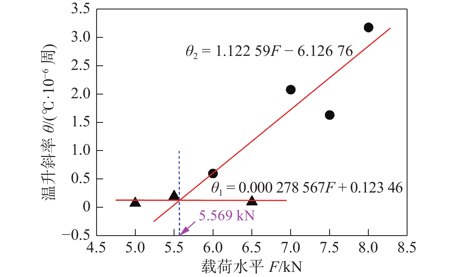
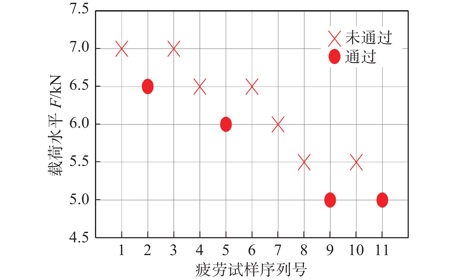
图 5 基于红外热像法的异种材料点焊接头疲劳强度评定
Figure 5. Fatigue strength assessment of dissimilar materials spot welded joint based on infrared thermography
表 1 试验材料名义化学成分(质量分数,%)
Table 1 Nominal chemical compositions of the test materials
材料 C Si Mn P S Cr Ni Ti Fe SUS301L-DLT ≤ 0.12 ≤ 0.08 ≤ 2.00 ≤ 0.035 ≤ 0.03 17 ~ 19 8 ~ 11 0.5 ~ 0.8 余量 Q235B 0.12 ~ 0.20 ≤ 0.30 0.30 ~ 0.67 ≤ 0.045 ≤ 0.045 — — — —  下载: 导出CSV
表 2 试验材料主要力学性能
Table 2 Major mechanical properties of the test materials
材料 屈服强度ReL/MPa 抗拉强度Rm/MPa 弹性模量 E/Pa 断后伸长率A(%) SUS301L-DLT ≥ 345 ≥ 689 1.8 × 10¹¹ ≥ 40 Q235B ≥ 235 375 ~ 500 2.1 × 10¹¹ ≥ 26
下载: 导出CSV
表 3 SUS301L-Q235B异种材料点焊接头静载拉伸性能
Table 3 Static load stretch performance of the SUS301L-Q235B dissimilar materials spot welded joint
接头类型 抗剪负荷 Pt/kN 抗剪负荷均值 $\overline {{P_{\rm t}}} $ /kN搭接点焊 32.815 6 31.641 7 32.000 0 30.109 4
下载: 导出CSV
-
[1] 朱国仁, 陈松, 李蒙蒙. SUS301L不锈钢非熔透型激光搭接焊缝的疲劳特性分析[J]. 焊接学报, 2016, 37(4): 14 − 19. Zhu Guoren, Chen Song, Li Mengmeng. Study on fatigue performance of stainless steel non-penetration laser lap welding of SUS301L stainless body[J]. Transactions of the China Welding Institution, 2016, 37(4): 14 − 19.
[2] 王希靖, 邓向槟, 王磊. Q235钢板与6082铝合金搅拌摩擦焊工艺[J]. 焊接学报, 2016, 37(1): 99 − 103. Wang Xijing, Deng Xiangbin, Wang Lei. Parametric study on friction stir welding of Q235 steel with 6082 aluminum alloy[J]. Transactions of the China Welding Institution, 2016, 37(1): 99 − 103.
[3] Liu Y L, Zou L, Sun Y B, et al. Evaluation model of aluminum alloy welded joint low-cycle fatigue data based on information entropy[J]. Entropy, 2017, 19(1): 1 − 14. doi: 10.3390/e19010037
[4] 刘亚良, 孙屹博, 邹丽, 等. 基于信息熵的铝合金焊接接头疲劳寿命分析方法[J]. 焊接学报, 2018, 39(4): 67 − 72. Liu Yaliang, Sun Yibo, Zou Li, et al. Fatigue life analysis method of aluminum alloy welded joints based on information entropy[J]. Transactions of the China Welding Institution, 2018, 39(4): 67 − 72.
[5] 封硕. 基于热力学分析的疲劳损伤与寿命预测研究[D]. 西安: 西北工业大学, 2015. [6] Rosa G L, Risitano A. Thermographic methodology for rapid determination of the fatigue limit of materials and mechanical components[J]. International journal of Fatigue, 2000, 22(1): 65 − 73. doi: 10.1016/S0142-1123(99)00088-2
[7] Luong M P. Fatigue limit evaluation of metals using an infrared thermographic technique[J]. Mechanics of Materials, 1998, 28(1-4): 155 − 163. doi: 10.1016/S0167-6636(97)00047-1
[8] Crupi V, Guglielmino E, Maestro M, et al. Fatigue analysis of butt welded AH36 steel joints: thermographic method and design S-N curve[J]. Marine Structures, 2009, 22(3): 373 − 386. doi: 10.1016/j.marstruc.2009.03.001
[9] Zhang H X, Wu G H, Yan Z F, et al. An experimental analysis of fatigue behavior of AZ31B magnesium alloy welded joint based on infrared thermography[J]. Materials and Design, 2014, 55: 785 − 791. doi: 10.1016/j.matdes.2013.10.036
[10] Peyroux R, Chrysochoos A, Licht C, et al. Thermomechanical couplings and pseudoelasticity of shape memory alloys[J]. International Journal of Engineering Science, 1998, 36(4): 489 − 509. doi: 10.1016/S0020-7225(97)00052-9
[11] Wagner D, Ranc N, Bathias C, et al. Fatigue crack initiation detection by an infrared thermography method[J]. Fatigue & Fracture of Engineering Materials & Structures, 2010, 33(1): 12 − 21.
[12] Yang H W, Cui Z Q, Wang W X, et al. Fatigue behavior of AZ31B magnesium alloy electron beam welded joint based on infrared thermography[J]. Transactions of Nonferrous Metals Society of China, 2016, 26(10): 2595 − 2602. doi: 10.1016/S1003-6326(16)64385-6


计量
- 文章访问数: 266
- HTML全文浏览量: 6
- PDF下载量: 12
